

Okofen PE 32, PE 15, PE 36, PE 48, PE 56 Operating Manual
...
Operating
Manual
+ Initial start up Pellet
heating system with auger
delivery system or vacuum
suction system for
professionals
PELLEMATIC®
PE(S)(K)(B) 10 — 56
FA_V2.03
Pelletronic TOUCH
ENGLISH
PE 567 EN 1.1 · www.oekofen.com

Title:
Operating Manual PELLEMATIC® PE(S)(K)(B) 10 — 56
Article number:
PE 567 EN 1.1
Version valid
from:
06/2015
Approved: Wohlinger Christian
Author
ÖkoFEN Forschungs- &.
EntwicklungsgesmbH
A-4133 Niederkappel, Gewerbepark 1
Tel.: +43 (0) 72 86 / 74 50
Fax.: +43 (0) 72 86 / 74 50 – 10
E-Mail: oekofen@pelletsheizung.at
© by ÖkoFEN Forschungs- und EntwicklungsgesmbH
www.oekofen.com Subject to modifcations

Operating Manual PELLEMATIC® PE(S)(K)(B) 10 — 56
11DDeeaarrCCuussttoommeerr .................................................................... .............. .............................................. .. .. .. .. .. .. .. .. .. .. .. .. .. .. .. .. .. .. .. .. .. .. .. .. .. .. .. .. .. .. .. .. .. .. .. .. .. .. .. .. .. .. .. .. .. .. .. .. .. .. .. .. .. .. .. .. .. .. .. .. .. .. .................................. 55
22UUsseeoonnllyyffoorrtthheeppuurrppoosseeiinntteennddeedd .............. .............. ........................................................................ .............. .............. .. .. .. .. .. .. .. .. .. .. .. .. .. .. .. .. .. .. .. .. .. .. .. .. .. .. .. .. .. .. .. .. .. .. .. .. .. .. .. .. .. .. .. .. .. 66
33TTyyppeessooffssaaffeettyywwaarrnniinnggssiiggnn...................................................................... ............................ .............................. .. .. .. .. .. .. .. .. .. .. .. .. .. .. .. .. .. .. .. .. .. .. .. .. .. .. .. .. .. .. .. .. .. .. .. .. .. .. .. .. .. .. .. .. .. .. .. .. .. .. .. .. .. .. .. .. 77
44SSyysstteemmoovveerrvviieeww .......................................................... .............. ........................................................ .. .. .. .. .. .. .. .. .. .. .. .. .. .. .. .. .. .. .. .. .. .. .. .. .. .. .. .. .. .. .. .. .. .. .. .. .. .. .. .. .. .. .. .. .. .. .. .. .. .. .. .. .. .. .. .. .. .. .. .. .. .. ...... .................. 88
55CCoonnttrrooll ssyys
stteemm ........................ ............................ .............. ............................ .................................. .. .. .. .. .. .. .. .. .. .. .. .. .. .. .. .. .. .. .. .. .. .. .. .. .. .. .. .. .. .. .. .. .. .. .. .. .. .. .. .. .. .. .. .. .. .. .. .. .. .. .. .. .. .. .. .. .. .. .. .. .. .. ..............................1100
66PPaarraammeetteerrAAddjjuussttmmeennttss ............................................ ............................ .............. ............................ .............. .. .. .. .. .. .. .. .. .. .. .. .. .. .. .. .. .. .. .. .. .. .. .. .. .. .. .. .. .. .. .. .. .. .. .. .. .. .. .. .. .. .. .. .. .. .. .. .. .. .. .. .. .. .. .. .. .. .. .. .. .. .. ..1111
77TThheebbooiilleerrccoonnttrroolllleerr .......................... ...................................................................................................... .. .. .. .. .. .. .. .. .. .. .. .. .. .. .. .. .. .. .. .. .. .. .. .. .. .. .. .. .. .. .. .. .. .. .. .. .. .. .. .. .. .. .. .. .. .. .. .. .. .. .. .. .. .. .. .. .. .. .. .. .. .. ............ 1122
7.1 Plugs on the boiler control unit ......................... . . . . . ....................... . . . . . ........................ . . ................................ 13
7.2 Wiring diagrams .... . . .................................................................................................................................... 15
7.3 LED status boiler controller....... . . . . . . ........................ . . .......................... . . ......................... . . . .......................... 19
7.4 Cable Routing.................. . . ........................... . .............................................................................................. 19
88TThheehheeaattiinnggccoonnttrroolllleerr .............................................................................. .............. ............................ ........ .. .. .. .. .. .. .. .. .. .. .. .. .. .. .. .. .. .. .. .. .. .. .. .. .. .. .. .. .. .. .. .. .. .. .. .. .. .. .. .. .. .. .. .. .. .. .. .. .. .. .. .. .. .. .. .. .. .. .. .. .. .. ....2200
8.1 LED status heating controller . . . ................................................................................................................... 21
8.2 Connection plan .................. . . . . . ....................... . . . .......................... . . ......................... . . . .................................22
8.2.1 Jumper X34 for analog voltage outputs X11 (OUT1) and X21 (OUT2) . ....................... . . . . .............25
8.3 Rules of wiring for micronetwork with 1,2 or more heating controllers ... . . . . ...............................................25
8.4 Wiring diagrams. . ....................... . . . . . ........................ . . . ......................... . . ..................................................... 26
8.5 Assembly and disassembly of the heating controller circuit board .......................................................... 28
8.6 Cable specification Pelletronic Touch...... . . ....................... . . . . . ........................ . . . . ........................................ 30
8.7 Sensor values..... . . .......................... . . ....................... . . . . . . ....................... . . . ..................................................... 31
8.8 Hydraulic connecting diagrams ..................................................................................................................32
8.8.1 Hydraulic connecting diagrams Pelletronic Touch ............... . . . ...................................................32
99TThheeTToouucchhooppeerraattiinnggddeevviiccee........ ............................ .............. .............................................................................. .. .. .. .. .. .. .. .. .. .. .. .. .. .. .. .. .. .. .. .. .. .. .. .. .. .. .. .. .. .. .. .. .. .. .. .. .. .. .. .. .. .. .. .. .. .. .. .. .. .. .. .. .. .. .. 4411
9.1 User controls and their function ........ . . ........................ . . . . ........................ . . . . ........................ . . . .................... 43
9.2 Main Menu .................................................................................................................................................. 45
9.3 Replacing a Touch operating device . . ......................... . . . ....................... . . . . . ............................................... 46
9.4 Backside of the Touch operating device .. . . . . ........................ . . ................................................................... 47
9.5 Calibration .................................................................................................................................................. 48
1100DDeeffaauullttvvaalluueessaannddsseettttiinnggss........................................................................ ............................ ............................ .. .. .. .. .. .. .. .. .. .. .. .. .. .. .. .. .. .. .. .. .. .. .. .. .. .. .. .. .. .. .. .. .. .. .. .. .. .. .. .. .. .. .. .. .. .. .. .. .. .. .. .. .. .. 4499
1111DDeeffaauullttvvaalluueessaannddsseettttiinnggss .......... ............................ .............. ........................................................................ .... .. .. .. .. .. .. .. .. .. .. .. .. .. .. .. .. .. .. .. .. .. .. .. .. .. .. .. .. .. .. .. .. .. .. .. .. .. .. .. .. .. .. .. .. .. .. .. .. .. .. .. .. .. .. .. 5533
1122OOnnlliin
neeTToouucchh .......................................... .............. ............................ .............. .............................. .. .. .. .. .. .. .. .. .. .. .. .. .. .. .. .. .. .. .. .. .. .. .. .. .. .. .. .. .. .. .. .. .. .. .. .. .. .. .. .. .. .. .. .. .. .. .. .. .. .. .. .. .. .. .. .. .. .. .. .. .. .. ................................ 5577
12.1 Product Description . . . .................................................................................................................................57
12.1.1 Installation Requirements ... . . . . ........................ . . . . ........................ . . . .......................... . ...................57
12.1.2 System Description .................................................................................................................... 58
12.2 Settings on the Touch Operating Device. ........................ . . . .......................... . ........................................... 59
12.3 Opening the Password-Protected Remote Maintenance Website ................... . . . . ...................... . . . . . . ........ 61
12.4 Description of the Pelletronic Online Website.......................................................................................... 62
12.4.1 Making Settings ........... . . . ....................... . . . . . . ....................... . . . .................................................... 63
12.4.2 Adjustment of the power rating . . ............................................................................................. 64
12.4.3 Error Messages by E-mail . . . . . ........................ . . . . ........................ . . .............................................. 65
12.4.4 Quit malfunction ........................ . . . . . . ......................................................................................... 67
12.4.5 Code input................................................................................................................................. 68
1133SSttaarrttiinngguuppffoorrtthheeffiirrssttttiimmee.......................................... .............. ............................ ............................................ .. .. .. .. .. .. .. .. .. .. .. .. .. .. .. .. .. .. .. .. .. .. .. .. .. .. .. .. .. .. .. .. .. .. .. .. .. .. .. .. .. .. .. .. .. .. .. .. .. .. .. .. .. 6699
13.1 Performance adjustment ...................... . . . . ........................ . . ....................................................................... 70
13.2 Setting the adresses of the Bus-participants............................................................................................ 70
13.2.1 Setting the address at the burner controller . . ...........................................................................70
13.2.2 Setting the address at the heating controller ......................... . . . . ............................................... 71
13.2.3 Setting the adress for the remote control . . . . ......................... . ........................... . . ......................72
13.2.4 Settings before starting up........................................................................................................72
13.2.5 Setting the adress for remote control Touch ...... . . . ...................................................................73
13.2.6 Setting the adress for remote control ...... . . ......................... . . . .................................................. 74
13.2.7 Code Input. ....................... . . . . . .....................................................................................................75
13.2.8 Periphery Learning.................. . . . .......................... . .....................................................................77
13.2.9 Flowtronic ........................ . . ........................... . ......................... . . . . ....................... . . . . . .................. 84
13.3 Mode.......................................................................................................................................................... 84
13.3.1 Operation mode.. . ........................... . . ....................... . . . . . . ...................... ...................................... 85
13.3.2 Operation mode HC 1 .... . . . . . ....................... . . . . ......................... . ........................... . . ..................... 85
Contents

Contents
13.3.3 Operation mode HC 2–6 ........................................................................................................... 85
13.3.4 Operation Mode DHW .............................................................................................................. 86
13.3.5 Operation mode solar ............................................................................................................... 86
13.3.6 Operation mode Pellematic . . ........................ . . .......................... . . .............................................. 87
13.4 Measuring values....................................................................................................................................... 87
13.5 Weather..................................................................................................................................................... 88
13.6 Eco Mode .................................................................................................................................................. 89
13.7 Heating Circuit.. . . . . . ........................ . . . ......................... . . ........................... . ................................................... 91
13.7.1 Screed programme . . ......................... . . . . ...................... . . . . . . ........................ . . ............................... 94
13.8 Solar Heating.... . . . .......................... . ......................... . . . . ...................... . . . . . . .................................................. 94
13.8.1 Menu Solar Heating...... . . . ....................... . . . . . . ....................... . . . . ......................... . ......................... 95
13.9 DHW settings ........................ . . . . . . ....................... . . . . ......................... . ........................... . . ............................ 96
13.10 DHW Return Pump settings . . ....................... . . . .......................... . . ......................... . . . ................................ 97
13.11 Solar settings .............. . ........................ . . . . . ....................... . . . . . ........................ . . .......................................... 98
13.12 Accumulator settings...................... . . . . ......................... . . .......................... . . .............................................104
13.13 System Regulation ................. . . . . ...................... . . . . . ......................... . . .......................... . . ...........................106
13.13.1 Cascade settings.................. . . . . ........................ . . . .......................... . ......................... . . . . ............. 107
13.13.2 Existing Boiler ...........................................................................................................................111
13.14 Pellematic settings ................................................................................................................................... 113
13.14.1 Outertemperature control... . . ................................................................................................... 114
13.14.2 External Power Ventilator........................................................................................................ 115
13.14.3 Permanent operation. . .......................... . ......................... . . . . ..................................................... 115
13.14.4 Ignition settings .......................................................................................................................116
13.14.5 Full power settings .................................................................................................................. 117
13.14.6 Run Down Time settings.. . . . . ........................ . . . . ........................ . . . .......................... . .................. 118
13.14.7 De-ashing system settings ................. . . . ....................... . . . . . . ....................... . . . . .......................... 119
13.14.8 Boiler cleaning ....................... . . . . . ........................ . . . ......................... . . ....................................... 121
13.14.9 Negative Draft . .......................... . ........................... . . ....................... . . . . . . .................................. 122
13.14.10 FRT Controller . . ........................ . . . . ........................ . . . .......................... . . .................................. 123
13.14.11 Level detection system ....... . . . . ...................... . . . . . . ........................ . . .......................... . . ............. 125
13.14.12 Boiler Controlled Pump . ......................... . . ........................... . ........................ . . . . . .................... 126
13.14.13 Suction turbine ....................... . . . ............................................................................................ 128
13.14.14 Output Settings ................. . . . . . ............................................................................................... 129
13.14.15 Output Test......... . . .................................................................................................................130
13.14.16 Maintenance .. . . . ....................... . . . ........................................................................................... 132
13.14.17 Calibrate........... . ..................................................................................................................... 133
13.14.18 Magnet Valve..................... . ................................................................................................... 134
13.14.19 Settings....................... . .......................................................................................................... 135
13.15 Heating Main Pump...................... . . . ........................................................................................................ 137
13.16 General settings .... . . . . . ......................... . . .................................................................................................. 138
13.16.1 Chimney................... . . . . . . ........................ . . . ................................................................................ 141
13.16.2 Datalog........... . . . . ........................ . . . . ........................ . . ........................... . . .................................. 142
13.16.3 Delete Log............. . . . . . ....................... . . . . .................................................................................. 143
13.16.4 ModBUS . . . ....................... . . . . . ........................ . . .........................................................................144
13.16.5 E-Mail ........ . . . . . ........................ . . . .......................... . ......................... . . . . ...................................... 146
13.16.6 IP Config .................... . . . ........................ . . . . . ....................... . . . . ......................... . ........................ 147
13.16.7 USB ............... . . . .......................... . ......................... . . . . ...................... . . . . . ....................................150
13.17 Software settings ............................ . . ........................ . . . . ........................ . . . . ............................................... 151
13.17.1 Configuration .......................... . . ....................... . . . . . ........................ . . . . .......................
................. 151
13.17.2 Function room sensor ................ . . . . . ....................... . . . . ......................... . . ......................... . . ....... 152
13.17.3 Update Heating Controller, Touch Operating device and Remote Control . . . . . . ..................... 152
13.17.4 Software Update................. . ........................ . . . . . ....................... . . . . . ........................ . . ................ 153
1144AAppppeennddiixx.... .............. ............................ .............. .................................................................... .. .. .. .. .. .. .. .. .. .. .. .. .. .. .. .. .. .. .. .. .. .. .. .. .. .. .. .. .. .. .. .. .. .. .. .. .. .. .. .. .. .. .. .. .. .. .. .. .. .. .. .. .. .. .. .. .. .. .. .. .. .. ................ ..........................115544
14.1 Malfunctions.............................................................................................................................................. 154
14.1.1 Malfunctions - what to do............. . . . ......................... . . ......................... . . . . ...................... . . . . . . ...... 154
14.1.2 Fault texts ........... . . . ................................................................................................................... 154
14.1.3 Malfunction report .................................................................................................................... 155
Operating Manual PELLEMATIC® PE(S)(K)(B) 10 — 56
Dear Customer 5
11 Dear Customer
ÖkoFEN is Europe’s leading specialist in pellet heating.
Proficiency, innovation and quality combined. This is the tradition on which ÖkoFEN shapes the future.
We are very pleased that you too have decided to purchase a product from ÖkoFEN.
• This manual is intended to help you operate the product safely, properly and economically.
• Please read this manual right through and take note of the safety warnings.
• Keep all documentation supplied with this unit in a safe place for future reference.
Please pass on the documentation to the new user if you decide to part with the unit at a later date.
• Please contact your authorised dealer if you have any questions.
ÖkoFEN attaches great importance to the development of new products. Our R&D Department repeatedly
challenges the effectiveness of tried-and-tested systems and works continuously on improvements. In this
way, we secure our technological advantage. We have already received many national and international
awards for our products.
All our products comply with European standards in respect of quality, efficiency and emissions.
Operating Manual PELLEMATIC® PE(S)(K)(B) 10 — 56

6
Use only for the purpose intended
22 Use only for the purpose intended
The pellet heating system is designed to heat water for central or other indirect heating systems and hot
water supply for buildings. It is not permissible to use the pellet heating system for any other purpose.
Reasonable foreseeable inadvertent uses for the heating system are not known.
PE 567 EN 1.1
Types of safety warning sign
7
33 Types of safety warning sign
The warning signs use the following symbols and texts.
Types of safety warning sign
1. Risk of injury
2. Consequences of risk
3. Avoiding risk
1. Risk of injury:
Danger - indicates a situation that could lead to death or lifethreatening injury.
Warning - indicates a situation that could lead life-threatening or
serious injury.
Caution - indicates a situation that could lead to injury.
Note - indicates a situation that could lead to property damage.
2. Consequences of risk
Effects and consequences resulting from incorrect operation.
3. Avoiding risk
Observing safety instructions ensures that the heating system is
operated safely
Operating Manual PELLEMATIC® PE(S)(K)(B) 10 — 56
8
System overview
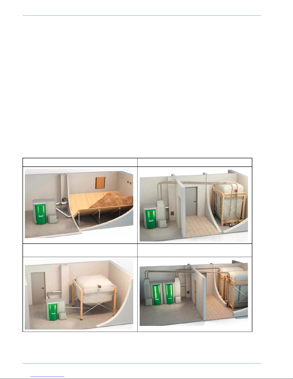
44 System overview
The whole system consists of following components:
ଉ Pellematic boiler:
• PE - Boiler with pellets transport auger as delivery system
• PES - Boiler with vacuum suction system as delivery system
• PEB - Boiler with hopper for hand filling
• PESKA - cascade with up to 4 possible boilers
ଉ Pellet storage room with pellet-delivery system:
• Storage room
• Textile tank
ଉ Possible additional components:
• Domestic hot water
• Accumulator
• Solar thermal panel
• Existing external boiler
Pellematic with storage room and auger delivery Pellematic with textile tank and auger delivery
Pellematic with storage room and vacuum
suction
Pellematic with textile tank and vacuum suction
PE 567 EN 1.1
System overview
9
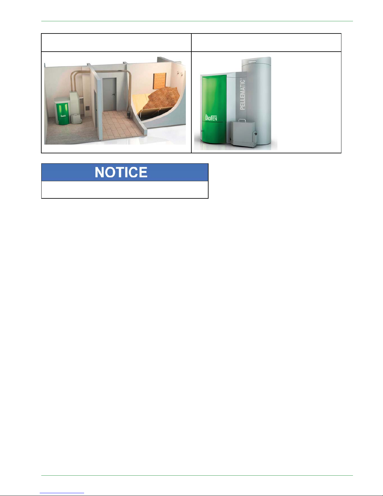
Pellematic cascade with textile tank and auger
delivery system
Pellematic with hopper for hand filling
There are seperate manuals for all components, which
describe functions and installation in detail.
Operating Manual PELLEMATIC® PE(S)(K)(B) 10 — 56
10
Control system
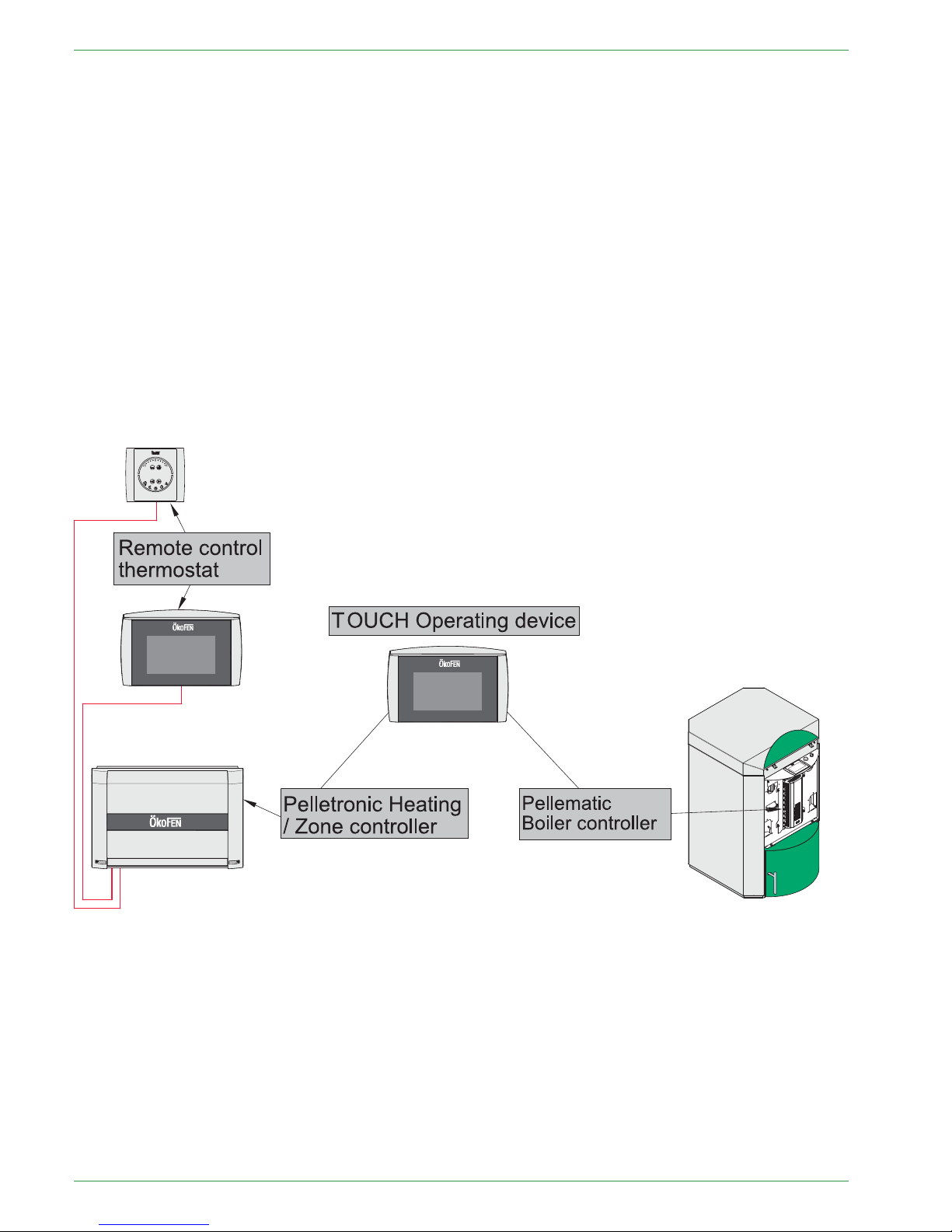
55 Control system
Basically the Controlsystem consists of following components:
• Pellematic boiler controller:
The boiler controller controls all boiler functions (pellet feed system, combustion, deashing, etc.)
• Pelletronic heating controller (max. 3 wall boxes = 6 zones, 3 domestic hot water, 3 accumulators)
The heating controller regulates the whole heat distribution system. (Room temperature, domestic hot
water, time programmes, solar, accumulator management, etc.)
Additionally remote controls can be installed in the system. These can be connected to the heat controller
by a bus-connection.
• Touch Operating Device
The Touch Operating Device is in the boiler. It is connected by a bus-connection with both, heating- and
boiler controller. It serves for:
– visualizing the measuring values
– adjusting the desired values and the time programme on the heating controller.
– adjusting the parameters of the boiler controller
PE 567 EN 1.1

Parameter Adjustments
11
66 Parameter Adjustments
There are two areas in which adjustments can be set:
• User-specific adjustments: e.g. Room temperature, Time program, Domestic hot water temperature,
Domestic hot water time program, Party-function etc.
• System-specific adjustments: e.g. combustion temperature regulation, deashing, ignition parameters,
suction interval, etc.
Ex works, adjustments are basically set, so no further adaption is neccessary.
A detailed description of all important setting options for the end user is to be found in the operating manual
of the End User.
Operating Manual PELLEMATIC® PE(S)(K)(B) 10 — 56

12
The boiler controller
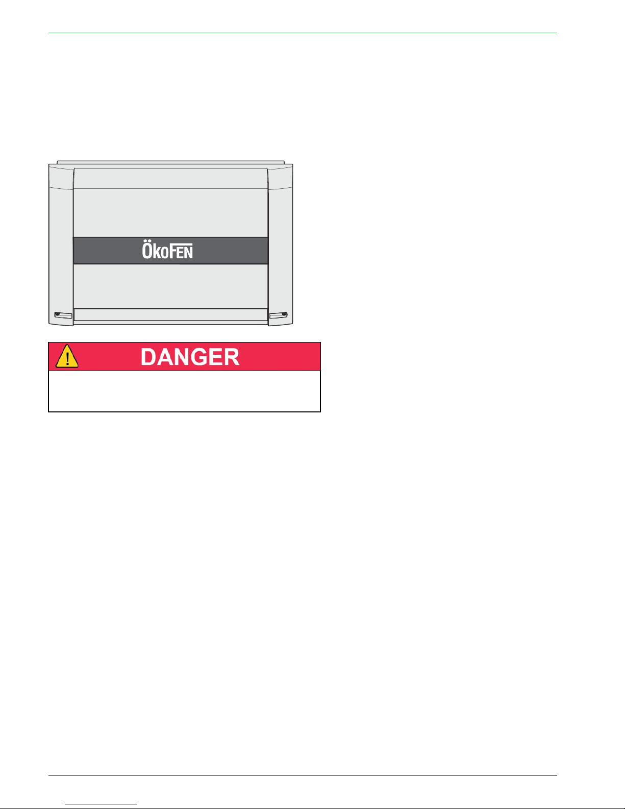
77 The boiler controller
The boiler controller is directly on the Pellematic boiler behind the half-round front cover of the boiler.
It is used to control the combustion process and the fuel-feeding system.
The boiler controller is connected to the touch operating device by a bus-connection.
The Touch allows the owner / operator to see important measured values and Change to "Provides for
adjustment of desired values and parameters of boiler operation. Only authorized installers should adjust
boiler operating parameters."
1 F1: Fuse T10A
2 F2: Fuse T8A
DDaammaaggeeooffpprrooppeerrttyy
Fuses must be replaced only with fuses having the same
current and voltage ratings.
PE 567 EN 1.1
Plugs on the boiler control unit
13
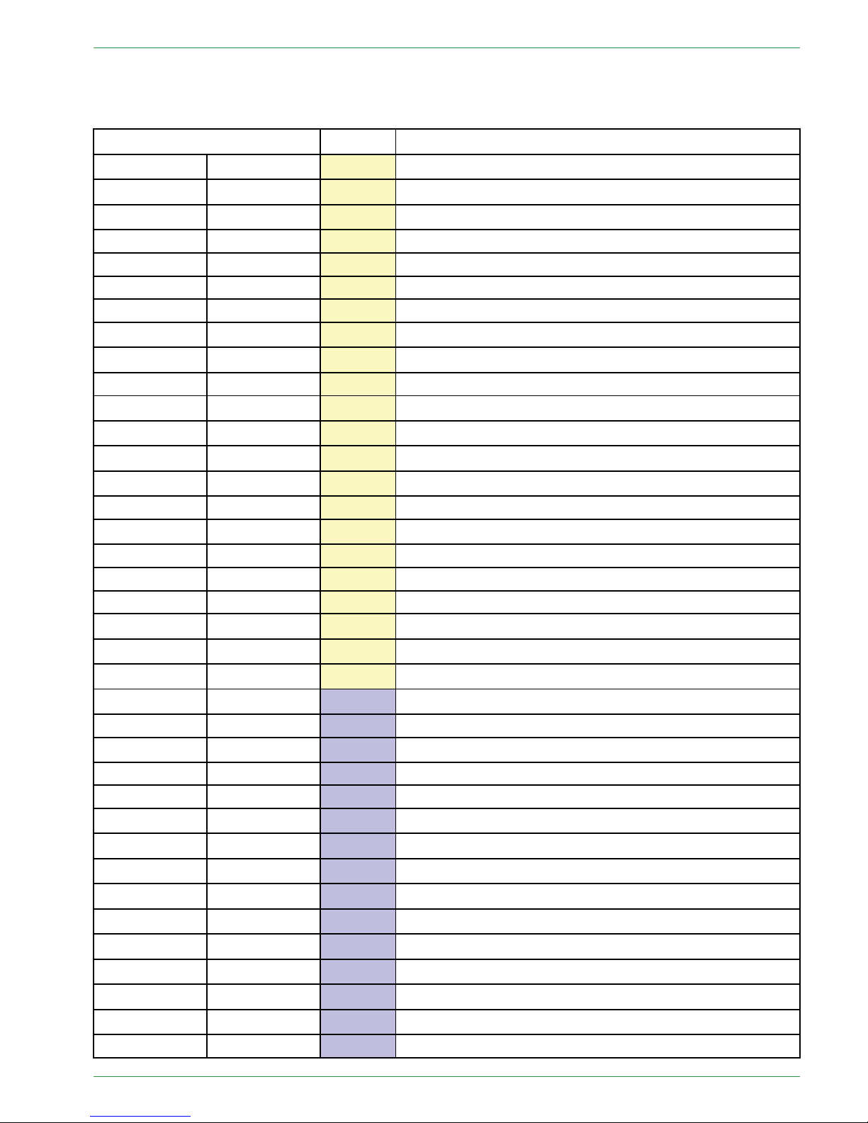
7.1 Plugs on the boiler control unit
The designation of the plugs must correspond with the labeling of plug-in positions.
Designation of plug-in position Voltage Name of sensors, motors and pumps
X1A
3 2 GND 1
24 Volt Operating display
X1B 3 2 GND 1
24 Volt Heating controller (BUS)
X2 5 4
24 Volt Power supply display
R1 46 45
24 Volt Not used
R2 44 43
24 Volt Not used
AF 42 41
24 Volt Not used
KF
89
24 Volt Boiler sensor
UP
234
24 Volt Negative draft measuring
AE2 5 6 7
24 Volt Level detection system
AE1
10 9 8
24 Volt Not used
FRT 12 13
24 Volt Combustion chamber temperature sensor
RGF 14 15
24 Volt Flue gas temperature sensor (optional)
PWM 16 17
24 Volt PWM for speed controlled high-efficiency pump
Analog IN
18 19
24 Volt Not used
BR1 7 8
24 Volt
Burner contact
AK 11 12
24 Volt Existing boiler (optional)
ESAV 32 33 34
24 Volt End switch ash box
DE 1 37 36 35
24 Volt Not used
DE 2 40 39 38
24 Volt Not used
KAPZW 26 25 24
24 Volt Capacitive sensor – hopper
KAPRA 5 4 3
24 Volt Capacitive sensor – burner
BSK 654321
24 Volt Flame return gate
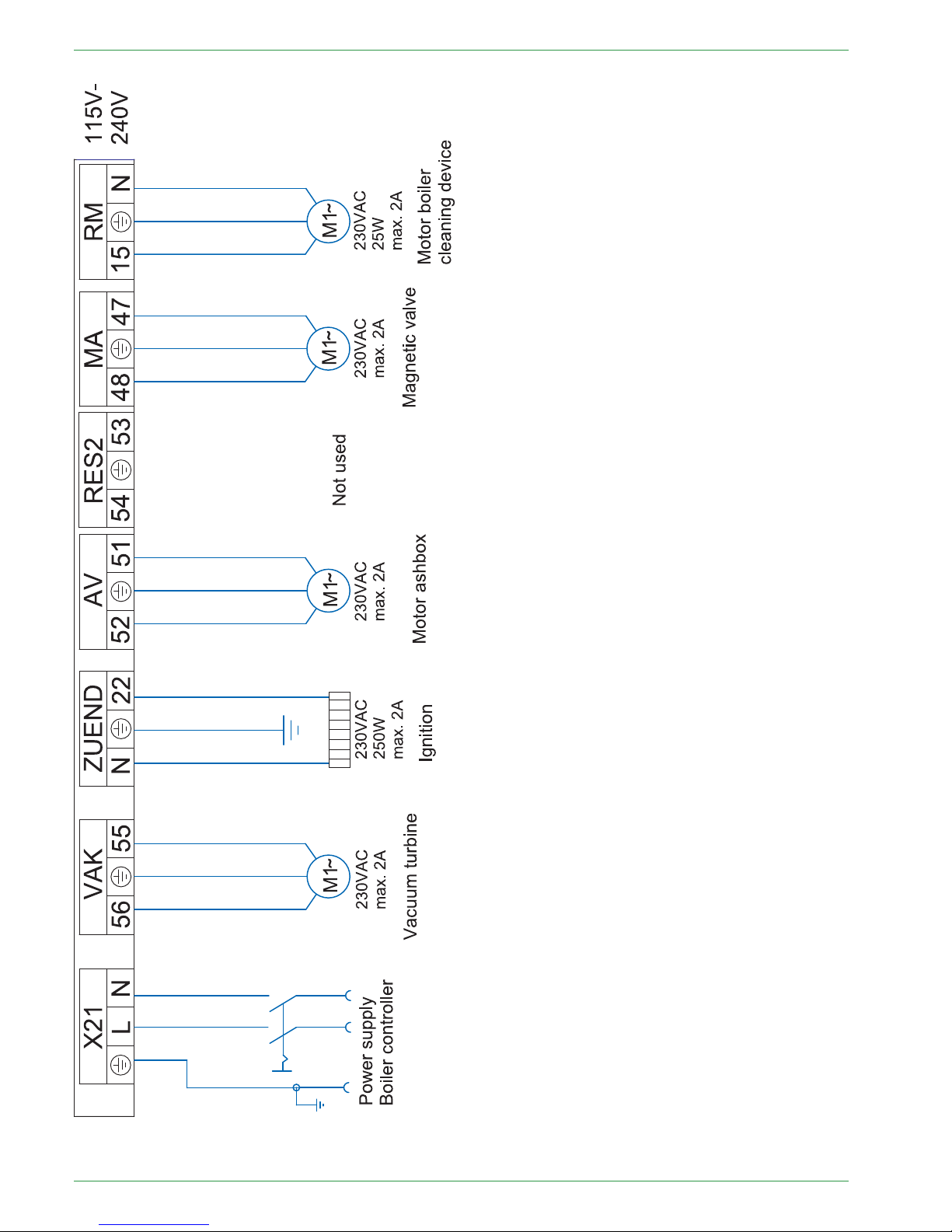
X21 PE L N
230 Volt Power supply
VAK 56 PE 55
230 Volt Vacuum turbine
ZUEND
NPE22
230 Volt
Ignition
AV 52 PE 51
230 Volt Motor ashbox
RES 2 54 PE 53
230 Volt Not used
MA 48 PE 47
230 Volt Magnetic valve (Cleaning nozzle, heat exchanger)
RM 15 PE N
230 Volt Motor boiler cleaning device
SM 19 20
230 Volt Relay fault signal (optional)
SZ 17 PE N
230 Volt Flue gas fan
UW 13 PE N
230 Volt Boiler controlled pump
STB 17 PE 19
230 Volt Safety temperature sensor
NOT 41 43
230 Volt Emergency stop heating
RA1 N PE 14 15 16
230 Volt Fuel transport system
RES1 50 PE 49
230 Volt Motor hopper – PES 36–56 only
ZW
NPE262524
230 Volt Vibration motor
Operating Manual PELLEMATIC® PE(S)(K)(B) 10 — 56

14
Plugs on the boiler control unit
ES 1 2 3 N PE 6
230 Volt
Burner motor
LUFT N PE 11
230 Volt Burner fan
PE 567 EN 1.1

Wiring diagrams
15
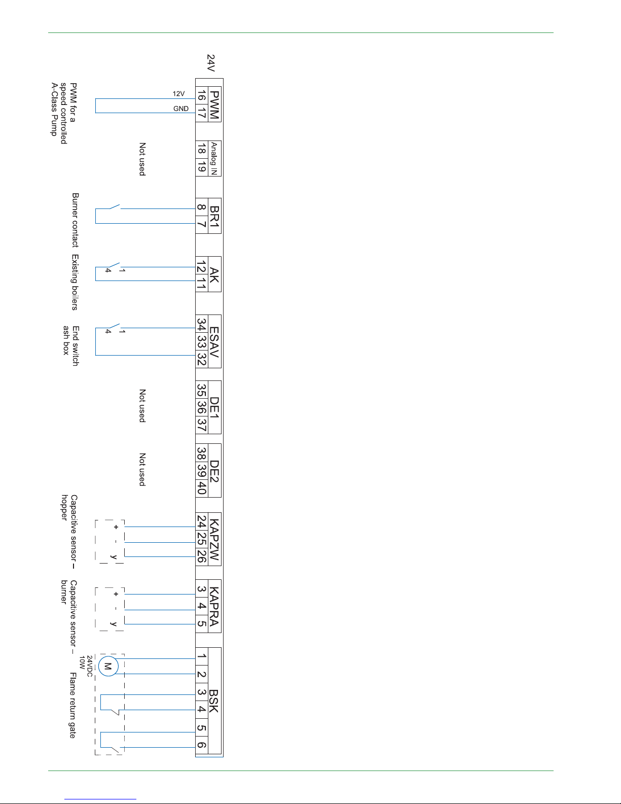
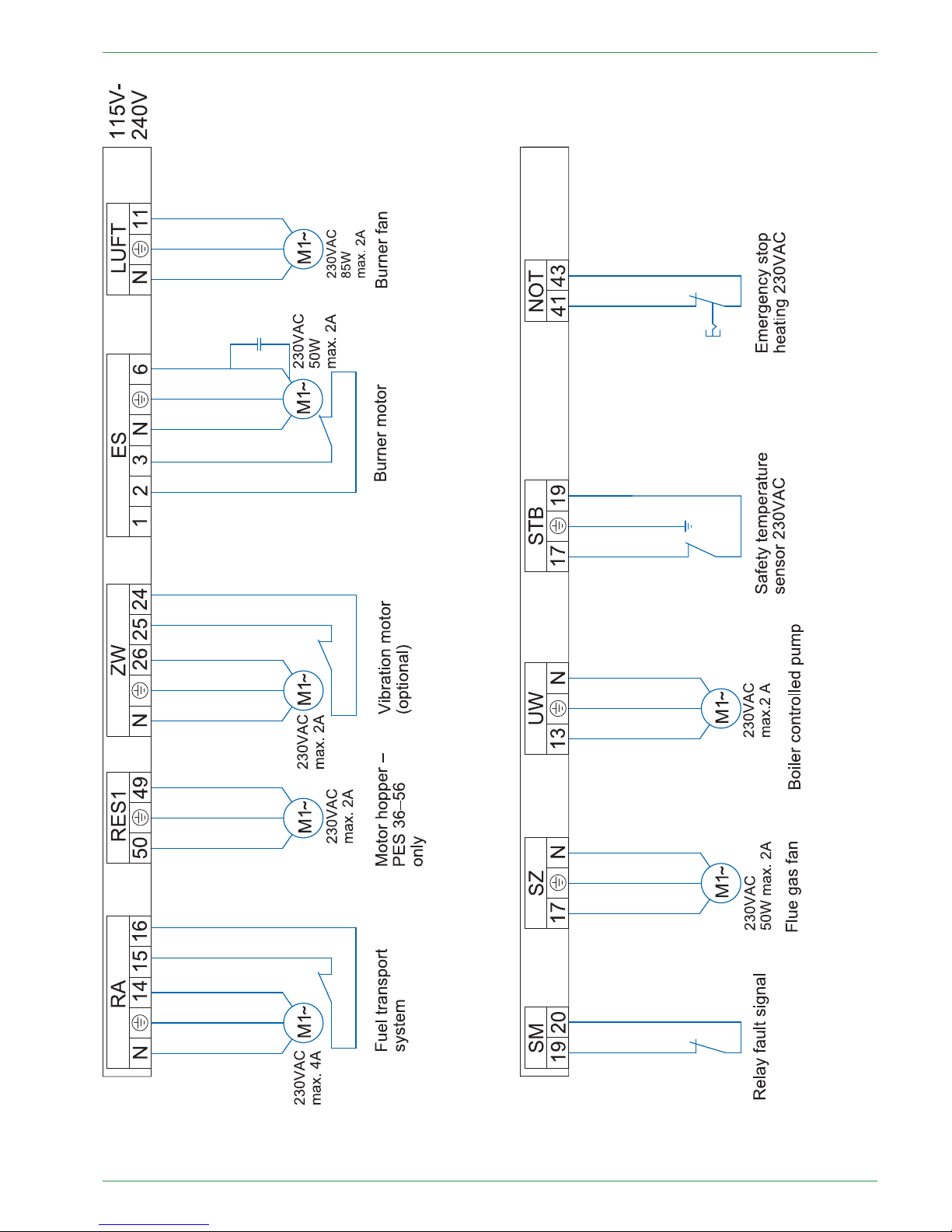
7.2 Wiring diagrams
The wiring diagrams for the boiler control unit provide detailed technical information for certified installers.
Only certified installers or electricians under the direction of a certified installer may connect to the
controller.
RRiisskkooffeelleeccttrriiccsshhoocckk
Only an authorised installer may connect the pellet boiler to the power supply.
Always disconnect / de-energize the power supply before working on the boiler.
Operating Manual PELLEMATIC® PE(S)(K)(B) 10 — 56
16
Wiring diagrams
PE 567 EN 1.1
Wiring diagrams
17
Operating Manual PELLEMATIC® PE(S)(K)(B) 10 — 56
18
Wiring diagrams
PE 567 EN 1.1

LED status boiler controller 19
7.3 LED status boiler controller
Display Description Cause and remedy
red Power supply present
—
red flashing Error condition
no communication possible
Check the software version
Check the bus wiring
Check the address
red / orange flashing
In the bus systems are devices using
the same address
Change the address
orange
Power supply present
Processor runs
No bus communication
Check the software version
Check the bus wiring
Check the address
orange flashing Firmware- update is in progress
—
green flashing Initialization (Firmware boots) If state is unchanged, software must
be checked.
green
Operation
Cyclic communication possible
—
7.4 Cable Routing
Th cable routing and the connection of the motors and sensors is precisely described in the Installation manual .
Operating Manual PELLEMATIC® PE(S)(K)(B) 10 — 56
20
The heating controller
88 The heating controller
The heating controller is in a wall box, which is in most cases installed nearby the heating circuit distributor.
It is used to control the whole heat distribution system for example: domestic hot water, room temperature,
solar system, accumulator, etc
It consists of a casing with an internal circuit board and terminals.
The cover plate of the casing is removable.
EElleeccttrriiccsshhoocckkddaannggeerr
Before opening, make sure that the whole heating
system is powerless.
Note:
The heating controller is limited to 8 amps total current draw. Also, each output is rated at 2 amps max.
Make sure that these values are not exceeded to avoid fuse failure.
PE 567 EN 1.1
LED status heating controller
21
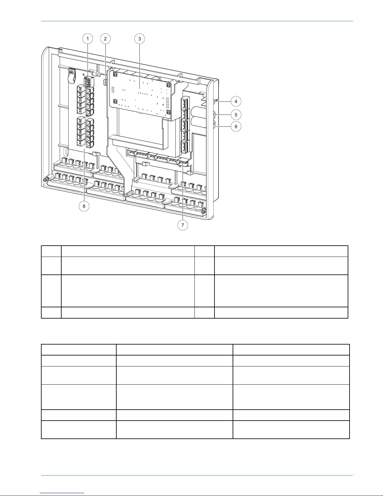
1
Bus connecting terminal RS485 A and B
5
Fuse 6,3 A (fast) for X31 and X33
2
Address switch
6
Fuse 8 A (slow-acting) limits the current
consumption of the heating controller.
3
Slot for an optional power supply
(The power supply is needed when the
burner control CMP 06.2 is used. The power
supply takes over the bus supply.)
7
Low voltage – area (dangerous voltage)
4 Status-LED 8
Extra low voltage (PELV)
8.1 LED status heating controller
Display Description Cause and remedy
red Power supply present
—
red flashing Error condition
no communication possible
Check software version
Check bus wiring
orange
Power supply present
Processor runs
no communication possible
Check bus wiring
green flashing Initialization (Firmware boots)
—
green
Operation
Cyclic communication possible
—
Operating Manual PELLEMATIC® PE(S)(K)(B) 10 — 56

22
Connection plan
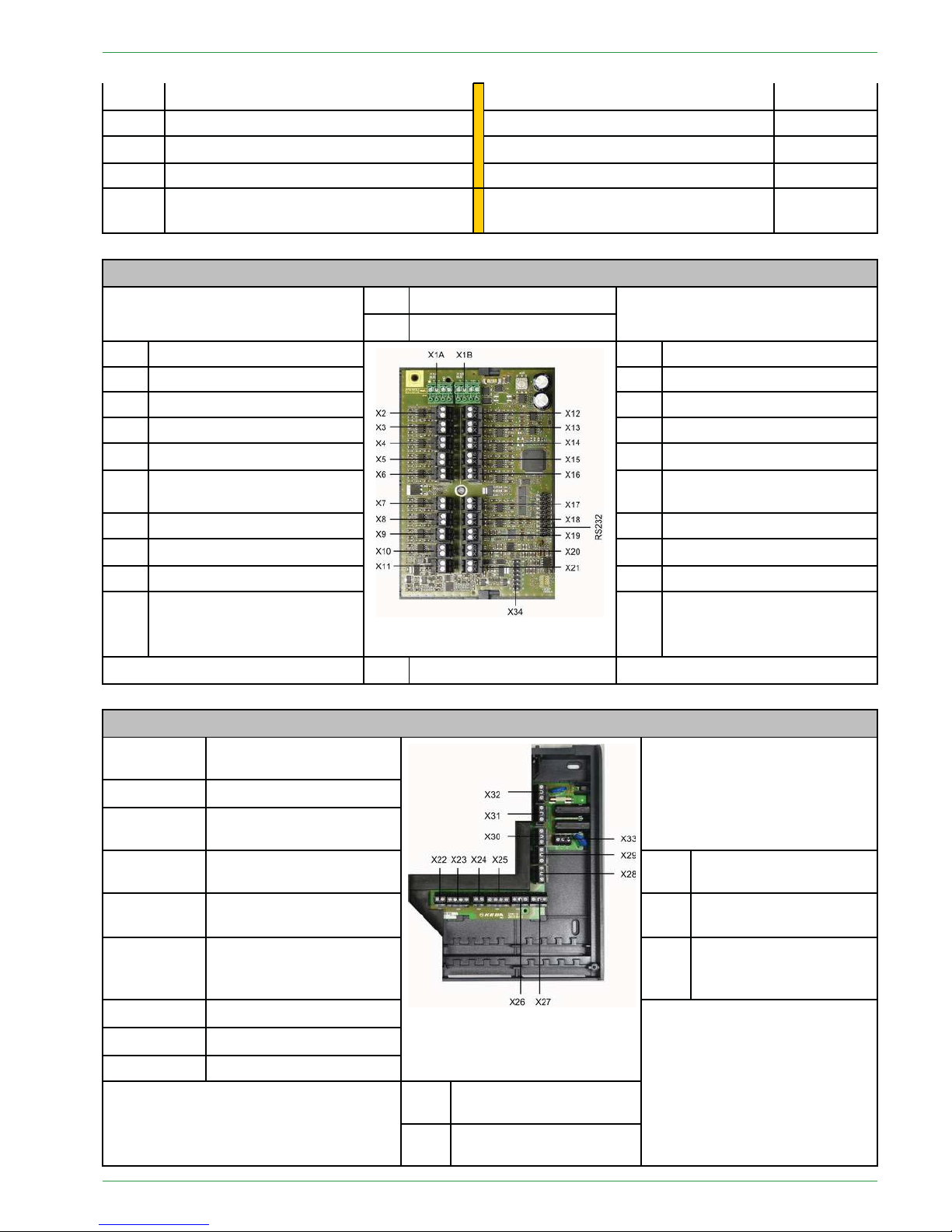
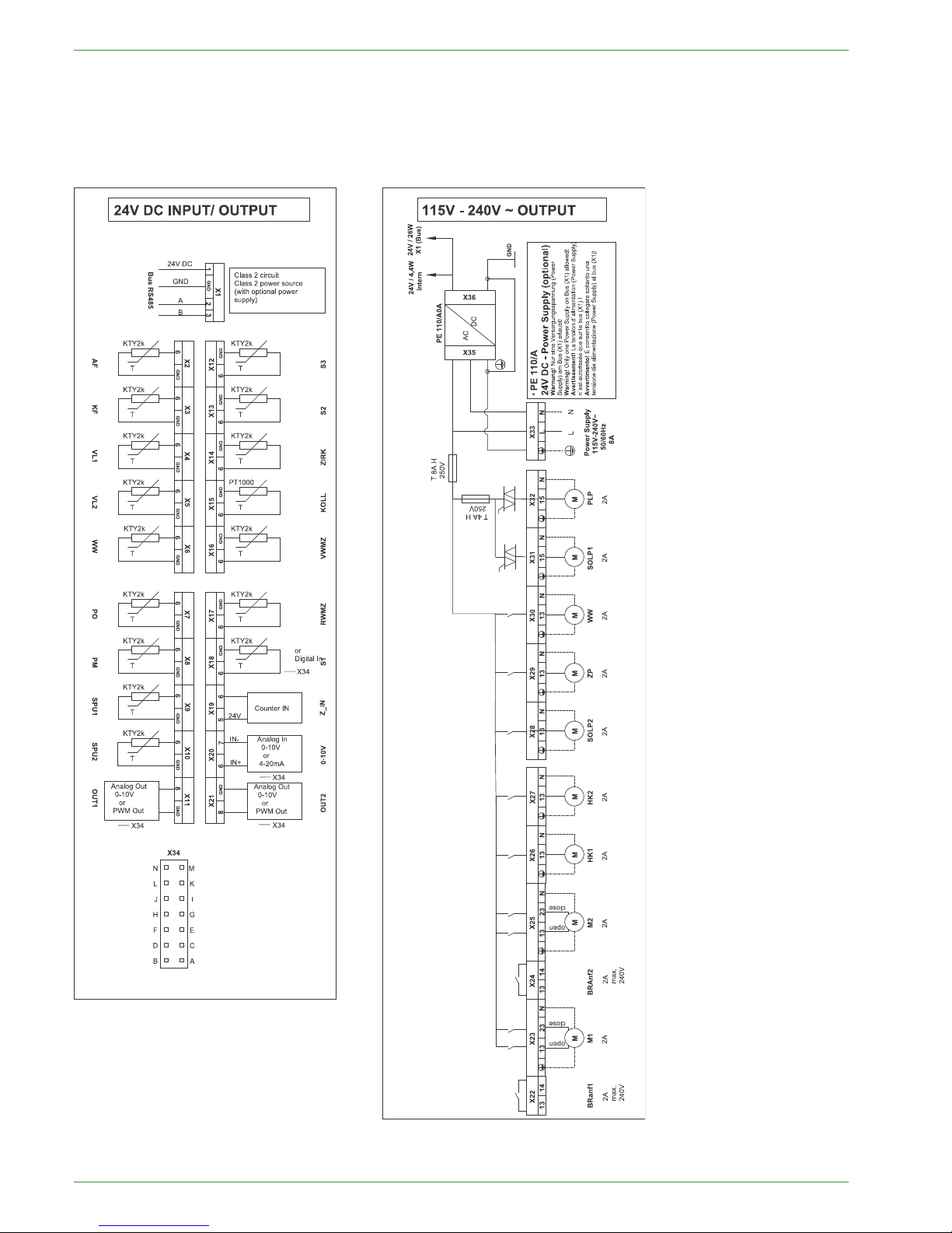
8.2 Connection plan
The Connection plan is a description of all the electrical connections from the Pelletronic heating controller:
Only an authorised installer may install and connect the
heating controller to the power supply.
Isolate the entire heating system from the power supply
before starting work on the heating controller.
Boiler sensor + outside sensor must be connected on
the first heating controller!
Terminals extra-low voltage zone Terminals low voltage zone - 120VAC
X1A Bus wiring – Bus RS485
Burner demand 1 – BRanf 1
X22
X1B Bus wiring – Bus RS485 Mixer HK1 opening – M1
X23 – 13/N
X2
Outdor sensor – AF Mixer HK1 closing – M1
X23 – 23/N
X3
Boiler sensor – KF Burner demand 2 – BRanf 2
(Potencial free contact)
X24
X4
Flow sensor HK1 – VL1
Mixer HK2 opening – M2
X25 – 13/N
X5
Flow sensor HK2 – VL2 Mixer HK2 closing – M2
X25 – 23/N
X6
DHW sensor – WW Heating circuit pump – HK1 X26
X7
AC upper sensor – PO Heating circuit pump – HK2 X27
X8
AC middle sensor – PM Solar pump 2 – Sol P2
X28
X9
AC lower sensor 1 – SPU1
Return pump – Heat main pump – ZP X29
X10
AC lower sensor 2 – SPU2 Domestic hot water – WW
X30
X11
Solar pump 1 A-class Solar pump 1– Sol P1
X31
X12 Reserve – S3
Accumulator pump – PLP
X32
X13 Reserve – S2
Power supply 115V – 240V~
X33
X14 Return sensor – ZIRK
X15
Collector sensor – KOLL
X16
Solar energy Flow – VWMZ
PE 567 EN 1.1
Connection plan
23
X17
Solar energy Return – RWMZ
X18 Reserve – S1
X19
Flow rate 24V – Z_IN
X20 Reserve – 0-10V
X21
Solar pump 2 A-class or Accumulator
pump A-class
Terminals extra-low voltage zone
X1A Bus wiring – Bus RS485
X1B Bus wiring – Bus RS485
X2
Outdor sensor – AF
X12 Reserve – S3
X3
Boiler sensor – KF
X13 Reserve – S2
X4
Flow sensor HK1 – VL1
X14 Return sensor – ZIRK
X5
Flow sensor HK2 – VL2
X15
Collector sensor – KOLL
X6
DHW sensor – WW
X16
Solar energy Flow – VWMZ
X7
AC upper sensor – PO
X17
Solar energy Return–
RWMZ
X8
AC middle sensor – PM
X18 Reserve – S1
X9
AC lower sensor 1 – SPU1
X19
Flow rate 24V – Z_IN
X10
AC lower sensor 2 – SPU2
X20 Reserve – 0-10V
X11
Solar pump 1 A-class
X21
Solar pump 2 A-class or Accumulator pump A-class
X34 Jumper
Terminals low voltage zone - 120VAC
X32
Accumulator pump –
PLP
X31
Solar pump 1– Sol P1
X30
Domestic hot water –
WW
X25 – 23/N
Mixer HK2 closing – M2
X33
Power supply 115V –
240V~
X25 – 13/N
Mixer HK2 opening – M2 X29
Return pump – Heat
main pump – ZP
X24
Burner demand 2 –
BRanf 2
(Potencial free contact)
X28
Solar pump 2 – Sol P2
X23 – 23/N
Mixer HK1 closing – M1
X23 – 13/N
Mixer HK1 opening – M1
X22
Burner demand – BRanf 1
X26 Heating circuit pump –
HK1
X27 Heating circuit pump –
HK2
Operating Manual PELLEMATIC® PE(S)(K)(B) 10 — 56
24
Connection plan
Electrical wiring diagrams heating controller
The wiring diagrams are also located on the inside of the cover of the heating controller.
Be aware of the instructions and diagrams illustrated there.
PE 567 EN 1.1

Jumper X34 for analog voltage outputs X11 (OUT1) and X21 (OUT2)
25
88..22..11JJuummppeerrXX3344ffoorraannaallooggvvoollttaaggeeoouuttppuuttssXX1111((OOUUTT11))aannddXX2211((OOUUTT22))
The different types of high-efficiency pumps: Analog pumps with 0-10 V control and PWM pumps with 24V.
For each type of pump you have to adjust the signal at the heating controller.
The plug connector X34 is for the Jumper-settings. Use a jumper with a grid dimension of 1 inch. The terminals X11 and X21 can receive or export a different signal depending on the jumper position.
Note:
When using PWM-pumps for a voltage up to 15V, adapter-cables must be connected at the slots X11 and
X12.
These cables limit the output voltage from 24V to 15V.
Jumpersettings X34:
The male connector X34 serves for jumper-adjustments. Please use jumper with a contact spacing of 1 inch
(included in delivery of heating controller)
High-efficiency
pump with external
control function
Terminal Designation Function Plug
connector
Position
Solar pump 1
X11 Out 1 PWM Out
Analog Out
0-10V
A-B and C-D
A-B and C-D
0
X
Solar pump 2
(or accumulator
pump)
X21 Out 2 PWM Out
Analog Out
0-10V
E-F and G-H
E-F and G-H
0
X
0.... Jumper is not set, pins open.
X.... Jumper is set, pins closed.
8.3 Rules of wiring for micronetwork with 1,2 or more heating
controllers
The boiler controller suplies the touch operating device and up to two remote controls.
• The order of devices in the bus-wiring is free. The station-numbers for the heating controller and the digital
remote controls have to be assigned uninterrupted.
• The number of heating controllers is independent from the numbers of the digital remote controls and independent from the numbers of boiler controllers.
•Adouble allocation is not acceptable.
• The maximum limit of bus-participiants is 16.
• The maximum length of a bus-cable is 200 metres.
• The maximum cable-length depends on:
– A solid point-to-point topology allows the fullmax. length.
–Astar-topology does not allow the max. length.
– We recommend a twisted-pair cable, especially for long cables (e.g. in buildings) and if the cable runs paralell to other cables.
– Correct bus-connection resistance, which is always existing on boiler operating device.
For long cables or communication problems occur, a additional resistor with 120 Ohm has to be clamped
between wire A and B at the last bus-participant.
When controlling a cascade-system, a bridge must be
installed at boiler controller port X2.
Operating Manual PELLEMATIC® PE(S)(K)(B) 10 — 56
26
Wiring diagrams
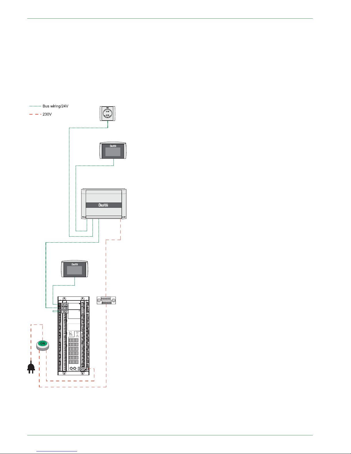
8.4 Wiring diagrams
Wiring diagram with:
• 1x Boiler controller FA
• 1x Heating controller Pelletronic
• 1x Touch operating device (Master)
• 1x Touch remote control (Slave)
• 1x Remote controll with LED
Note:
You find more detailed information about wiring in chapter 8.3 Rules of wiring for micronetwork with 1,2
or more heating controllers, page 25
PE 567 EN 1.1
Wiring diagrams
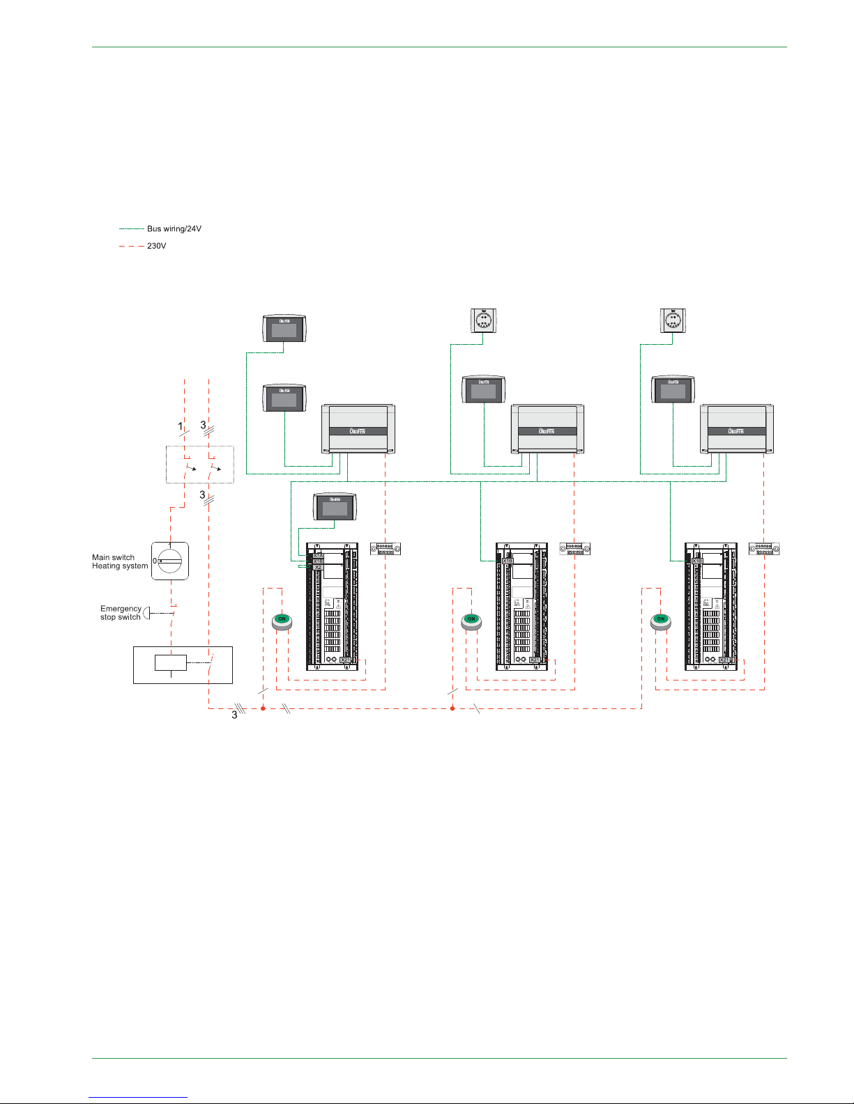
27
Wiring diagram with:
• 3x Boiler controller FA
• 3x Heating controller Pelletronic
• 1x Touch operating device (Master)
• 4x Touch remote control (Slave)
• 2x remote controll with LED
Note:
You find more detailed information about wiring in chapter 8.3 Rules of wiring for micronetwork with 1,2
or more heating controllers, page 25
Operating Manual PELLEMATIC® PE(S)(K)(B) 10 — 56
28
Assembly and disassembly of the heating controller circuit board
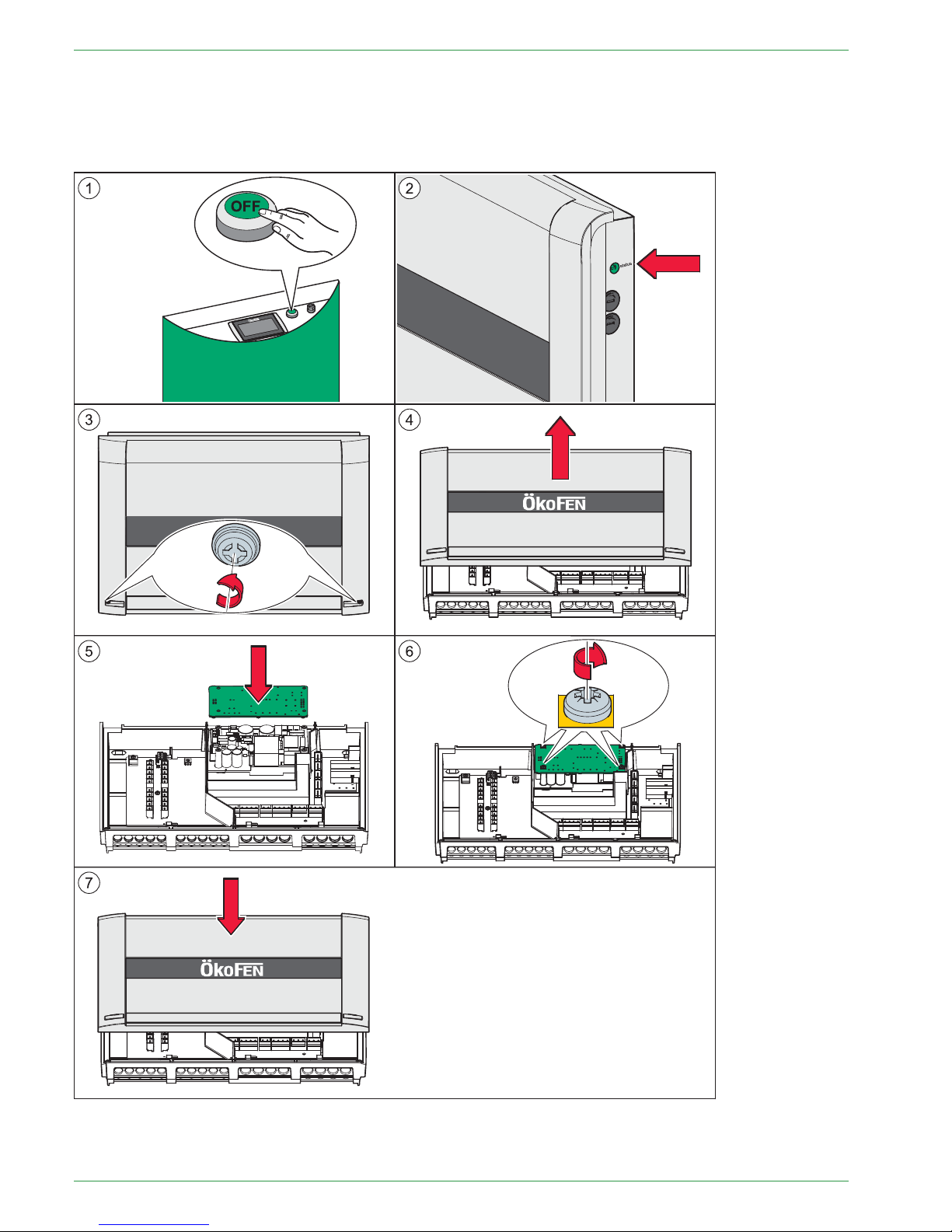
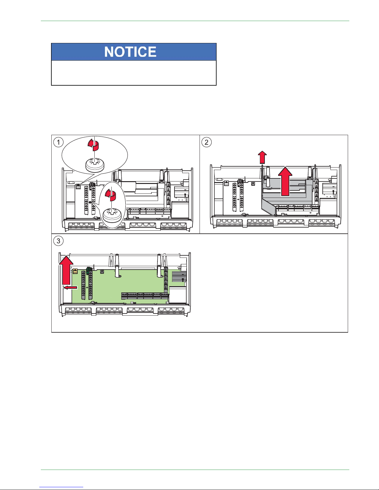
8.5 Assembly and disassembly of the heating controller circuit
board
You can take off the circuit board of the heating controller, without filtering out the inputs and outputs.
Note:
Image 2: Control with the status of the LED that the heating controller is electroless.
PE 567 EN 1.1
Assembly and disassembly of the heating controller circuit board
29
1. Make the complete heating system powerless.
EElleeccttrroossttaattiiccddiisscchhaarrggeeddaammaaggee
Before starting work, touch a grounded object to avoid
damage of circuit board by electrostatic charging.
2. Open the cover plate of the heating controller.
3. Disconnect all plugs from the circuit board. Leave the plugs with the wiring in the casing.
4. Disassembly from the power supply (optional)
5. Disassembly the circuit board from the heating controller.
6. The installation of a new circuit board occurs in reverse order.
Operating Manual PELLEMATIC® PE(S)(K)(B) 10 — 56
30
Cable specification Pelletronic Touch
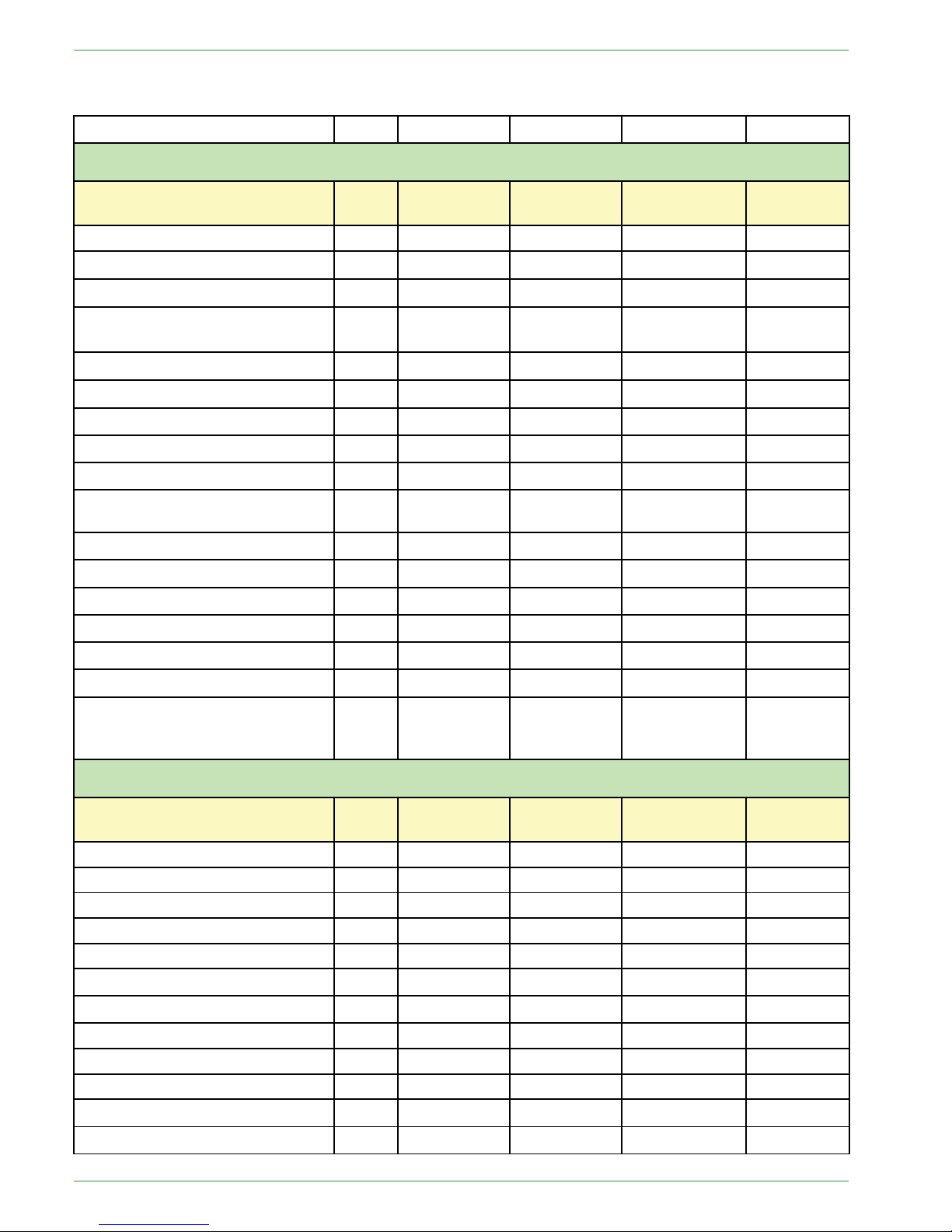
8.6 Cable specification Pelletronic Touch
Power supply
K02
X33 YML-J 3x1
x
OUTPUTS see on wiring diagram on the front side
Function – Shortcut
Cable
Pin I/O BOX
Cable type Section
Max
Ampere
Burner contact 1 – BRanf 1
K 03 X22
YML-J
3x0.75 2A
Mixer HK1 OPEN – M1 K 12
X23 – 13/N
YML-J
3x0.75 2A
Mixer HK1 CLOSED – M1 K 12
X23 – 23/N
YML-J
3x0.75 2A
Burner contact 2 – BRanf 2
(Potencial free contact)
K 30 X24
YML-J
3x0.75 2A
Mixer HK2 OPEN – M2 K 13
X25 – 13/N
YML-J
3x0.75 2A
Mixer HK2 CLOSED – M2
K13
X25 – 23/N
YML-J
3x0.75 2A
Heating circuit pump – HK1 K 14 X26
YML-J
3x0.75 2A
Heating circuit pump – HK2 K 15 X27
YML-J
3x0.75 2A
Solar pump 1 – Sol P1
K 16 X31 YML-J 3x0.75 2A
Return pump – Heat main pump –ZPK 29 X29
YML-J
3x0.75 2A
Domestic hot water pump – WW
K 21 X30
YML-J
3x0.75 2A
Solar pump 2 – Sol P2
K 23 X28 YML-J
3x0.75 2A
Accumulator pump – PLP
K 05 X32 YML-J 3x0.75 2A
Bus wiring – Bus RS485 K 01 X1A YSLCY–0Z 4x0.75
x
Bus wiring – Bus RS485 X1B YSLCY–0Z 4x0.75
x
Solar high-efficiency pump 1
K 28 X11 YML
2x0.75
x
Solar high-efficiency pump 2 or
Accumulator high-efficiency
pump
K 71 X21
YML
2x0.75
x
INPUTS see on wiring diagram on the front side
Function – Shortcut
Cable
Pin I/O BOX
Cable type Section
Max
Ampere
Outdor sensor – AF
K 09 X2 YML 2x0.75
KTY 2k
Boiler sensor – KF
K04
X3 YML
2x0.75
KTY 2k
Flow sensor HK1 – VL1
K 10 X4 YML 2x0.75
KTY 2k
Flow sensor HK2 – VL2
K 11 X5 YML
2x0.75
KTY 2k
DHW sensor – WW
K19 X6
YML
2x0.75
KTY 2k
AC upper sensor (TPO) – PO K 18
X7 YML
2x0.75
KTY 2k
AC middle sensor (TPM) – PM
K 17 X8 YML
2x0.75
KTY 2k
AC lower sensor 1 – SPU1
K20 X9
YML
2x0.75
KTY 2k
AC lower sensor 2 – SPU2
K 22 X10
YML
2x0.75
KTY 2k
Reserve sensor – S3 X12 YML
2x0.75
KTY 2k
Sensor existing boiler – S2
X13 YML
2x0.75
KTY 2k
Sensor return pump – ZIRK K 29 X14 YML 2x0.75
KTY 2k
PE 567 EN 1.1
 Loading...