

OKM eXp 4000, FS Future eXp 4000 User Manual
FS Future Series
eXp 4000
Version 2.1
User's Manual

Any information contained in these operating instructions may be changed without prior notice.
OKM does not make any warranty for this document. This also applies without limitation to implied assurances of
merchantability and fitness for a specific purpose. OKM does not assume any responsability for errors in this manual
or for any incidental or consequential damage or loss associated with the delivery, exploitation or usage of this
material.
This documentation is available "as presented" and without any kind of warranty. In no circumstances OKM takes
responsibility for lost profits, usage or data losts, interruption of business activities or all kind of other indirectly
damages, which developed because of errors in this documentation. This instruction manual and all other stored
media, which are delivered with this package should only be used for this product. Program copies are allowed only
for security- and savety purposes. The resale of these programs, in original or changed form, is absolutely forbitten.
This manual may not be copied, duplicated or translated into another language, neither in part nor completely, over
the copyright matters without the prior written consent of OKM.
Copyright ©2002 – 2010 OKM Ortungstechnik GmbH. All rights reserved.

3
Table of Contents
1 Introduction ........................................................................................................................................... 7
1.1 Preface ........................................................................................................................................... 8
1.2 Important Notes ............................................................................................................................. 9
1.2.1 General Notes ........................................................................................................................ 9
1.2.2 Possible Health Hazards ......................................................................................................... 9
1.2.3 Surrounding Area ................................................................................................................... 9
1.2.4 Voltage ................................................................................................................................... 9
1.2.5 Data safety ........................................................................................................................... 10
1.3 Maintenance and Services ........................................................................................................... 10
1.4 Danger of Explosion during Excavation ....................................................................................... 10
2 Install/Uninstall USB drivers on Windows ........................................................................................... 13
2.1 Windows XP ................................................................................................................................. 14
2.1.1 Install USB drivers on Windows XP ...................................................................................... 14
2.1.2 Uninstall USB drivers on Windows XP ................................................................................. 17
2.2 Windows Vista .............................................................................................................................. 20
2.2.1 Install USB drivers on Windows Vista .................................................................................. 20
2.2.2 Update USB drivers on Windows Vista ................................................................................. 22
2.2.3 Uninstall USB drivers on Windows Vista .............................................................................. 26
2.3 Windows 7 .................................................................................................................................... 27
2.3.1 Install USB drivers on Windows 7 ........................................................................................ 27
2.3.2 Uninstall USB drivers on Windows 7 .................................................................................... 32
3 Technical Specifications ....................................................................................................................... 33
3.1 Control Unit ................................................................................................................................. 34
3.2 Data Transmission ........................................................................................................................ 34
3.3 Computer, Minimum Requirements ............................................................................................. 34
4 Scope of Delivery ................................................................................................................................. 35
5 Assembly .............................................................................................................................................. 37
6 Control Elements ................................................................................................................................. 41
6.1 Control Unit ................................................................................................................................. 43
6.1.1 Front View ............................................................................................................................ 43
6.1.2 Rear View ............................................................................................................................. 44
7 Operating Modes ................................................................................................................................. 45
7.1 Magnetometer .............................................................................................................................. 47
7.2 Ground Scan ................................................................................................................................ 48
7.2.1 New Scan ............................................................................................................................. 49
7.2.2 Browse Scans ....................................................................................................................... 51
7.3 Metal Detector ............................................................................................................................. 52
7.4 Discrimination .............................................................................................................................. 52
7.5 Empty Memory ............................................................................................................................. 54
OKM Ortungstechnik GmbH
www.okmmetaldetectors.com

7.6 Exit ............................................................................................................................................... 54
7.7 Thermograph ............................................................................................................................... 55
7.8 Thermo Scan ................................................................................................................................ 55
8 Field procedure .................................................................................................................................... 57
8.1 General scanning procedure ....................................................................................................... 58
8.1.1 Scan Mode ............................................................................................................................ 58
8.1.2 Regulation of the number of impulses per scanning path .................................................... 59
8.2 Special advices for field procedure .............................................................................................. 61
8.2.1 Orientation of probe ............................................................................................................. 62
8.2.2 Parallel or Zig-Zag? .............................................................................................................. 62
8.2.3 Manual or automatic impulse mode? .................................................................................... 63
8.2.4 Tips from the trainers themselves ........................................................................................ 63
9 Optional Equipment ............................................................................................................................. 65
9.1 Super Sensor ................................................................................................................................ 66
9.1.1 Usage ................................................................................................................................... 66
9.2 DDV system .................................................................................................................................. 67
9.2.1 Calibration ........................................................................................................................... 67
9.2.2 Adjust the discriminator ....................................................................................................... 69
9.2.3 Ground Balance .................................................................................................................... 70
4
10 Error Messages .................................................................................................................................. 71
OKM Ortungstechnik GmbH
www.okmmetaldetectors.com

5
Illustration Index
Illustration 2.1: Install USB drivers: Windows XP, Step 1 ....................................................................... 14
Illustration 2.2: Install USB drivers: Windows XP, Step 2 ....................................................................... 14
Illustration 2.3: Install USB drivers: Windows XP, Step 3 ....................................................................... 15
Illustration 2.4: Install USB drivers: Windows XP, Step 4 ....................................................................... 15
Illustration 2.5: Install USB drivers: Windows XP, Step 5 ....................................................................... 16
Illustration 2.6: Install USB drivers: Windows XP, Step 6 ....................................................................... 16
Illustration 2.7: Uninstall USB drivers: Windows XP, Step 1 ................................................................... 17
Illustration 2.8: Uninstall USB drivers: Windows XP, Step 2 ................................................................... 17
Illustration 2.9: Uninstall USB drivers: Windows XP, Step 3 ................................................................... 18
Illustration 2.10: Uninstall USB drivers: Windows XP, Step 4 ................................................................. 18
Illustration 2.11: Uninstall USB drivers: Windows XP, Step 5 ................................................................. 19
Illustration 2.12: Install USB drivers: Windows Vista, Step 1 ................................................................. 20
Illustration 2.13: Install USB drivers: Windows Vista, Step 2 ................................................................. 20
Illustration 2.14: Install USB drivers: Windows Vista, Step 3 ................................................................. 21
Illustration 2.15: Install USB drivers: Windows Vista, Step 4 ................................................................. 21
Illustration 2.16: Install USB drivers: Windows Vista, Step 5 ................................................................. 21
Illustration 2.17: Update USB drivers on Windows Vista, Step 1 ............................................................ 22
Illustration 2.18: Update USB drivers on Windows Vista, Step 2 ............................................................ 22
Illustration 2.19: Update USB drivers on Windows Vista, Step 3 ............................................................ 23
Illustration 2.20: Update USB drivers on Windows Vista, Step 4 ............................................................ 23
Illustration 2.21: Update USB drivers on Windows Vista, Step 5 ............................................................ 24
Illustration 2.22: Update USB drivers on Windows Vista, Step 6 ............................................................ 24
Illustration 2.23: Update USB drivers on Windows Vista, Step 7 ............................................................ 25
Illustration 2.24: Uninstall USB drivers on Windows Vista, Step 1 ......................................................... 26
Illustration 2.25: Uninstall USB drivers on Windows Vista, Step 2 ......................................................... 26
Illustration 2.26: Install USB drivers on Windows 7 - Step 1 .................................................................. 27
Illustration 2.27: Install USB drivers on Windows 7 - Step 2 .................................................................. 27
Illustration 2.28: Install USB drivers on Windows 7 - Step 3 .................................................................. 27
Illustration 2.29: Install USB drivers on Windows 7 - Step 4 .................................................................. 28
Illustration 2.30: Install USB drivers on Windows 7 - Step 5 .................................................................. 28
Illustration 2.31: Install USB drivers on Windows 7 - Step 6 .................................................................. 29
Illustration 2.32: Install USB drivers on Windows 7 - Step 7 .................................................................. 29
Illustration 2.33: Install USB drivers on Windows 7 - Step 8 .................................................................. 30
Illustration 2.34: Install USB drivers on Windows 7 - Step 9 .................................................................. 30
Illustration 2.35: Install USB drivers on Windows 7 - Step 10 ................................................................ 31
Illustration 2.36: Uninstall USB drivers on Windows 7 - Step 1 .............................................................. 32
Illustration 2.37: Uninstall USB drivers on Windows 7 - Step 2 .............................................................. 32
Illustration 5.1: Connection of probe ...................................................................................................... 38
Illustration 5.2: Connection of Power Pack ............................................................................................. 38
Illustration 5.3: Connection of headphones ............................................................................................ 38
Illustration 5.4: Connection of joystick ................................................................................................... 39
Illustration 6.1: Control unit with power supply and probe .................................................................... 42
Illustration 6.2: Control unit, front view ................................................................................................. 43
Illustration 6.3: Control unit, rear view .................................................................................................. 44
Illustration 7.1: Magnetometer: Main Menu, Representation of Values .................................................. 47
Illustration 7.2: Ground Scan .................................................................................................................. 48
OKM Ortungstechnik GmbH
www.okmmetaldetectors.com

Illustration 7.3: Ground Scan – Submenu ............................................................................................... 48
Illustration 7.4: Ground Scan – Parameter .............................................................................................. 49
Illustration 7.5: Zig-Zag or Parallel ......................................................................................................... 49
Illustration 7.6: Start first scan line? ...................................................................................................... 50
Illustration 7.7: Graphical Representation of a Measurement in Operating Mode Ground Scan ............ 50
Illustration 7.8: Select Stored Measurement .......................................................................................... 51
Illustration 7.9: Submenu: Browse Scans ............................................................................................... 51
Illustration 7.10: Metal Detector ............................................................................................................. 52
Illustration 7.11: Discrimination ............................................................................................................. 52
Illustration 7.12: Signature of a ferromagnetic metal target .................................................................. 53
Illustration 7.13: Signature of a non-ferromagnetic metal target .......................................................... 53
Illustration 7.14: Signature of a non-metallic target ............................................................................... 53
Illustration 7.15: Empty Memory ............................................................................................................ 54
Illustration 7.16: Exit .............................................................................................................................. 54
Illustration 9.1: Position of Super Sensor ............................................................................................... 66
Illustration 9.2: Control Elements of the Detector .................................................................................. 67
Illustration 9.3: Calibration of the DDV system, step 1 ........................................................................... 68
Illustration 9.4: Calibration of the DDV system, step 2 ........................................................................... 68
Illustration 9.5: Adjustment of discrimination ......................................................................................... 69
Illustration 10.1: Only a small amount of memory available ................................................................... 72
Illustration 10.2: No free memory available ............................................................................................ 72
Illustration 10.3: Internal Hardware Error ............................................................................................. 72
Illustration 10.4: The external power supply has to be charged ............................................................. 73
Illustration 10.5: Shutting down the system ........................................................................................... 73
Illustration 10.6: Shutting down the system is not possible .................................................................... 73
6
OKM Ortungstechnik GmbH
www.okmmetaldetectors.com

1 Introduction
CHAPTER 1
Introduction

8 Introduction
1.1 Preface
Dear customer,
all of the engineers, sales, training and support staff at OKM Ortungstechnik GmbH would like to thank
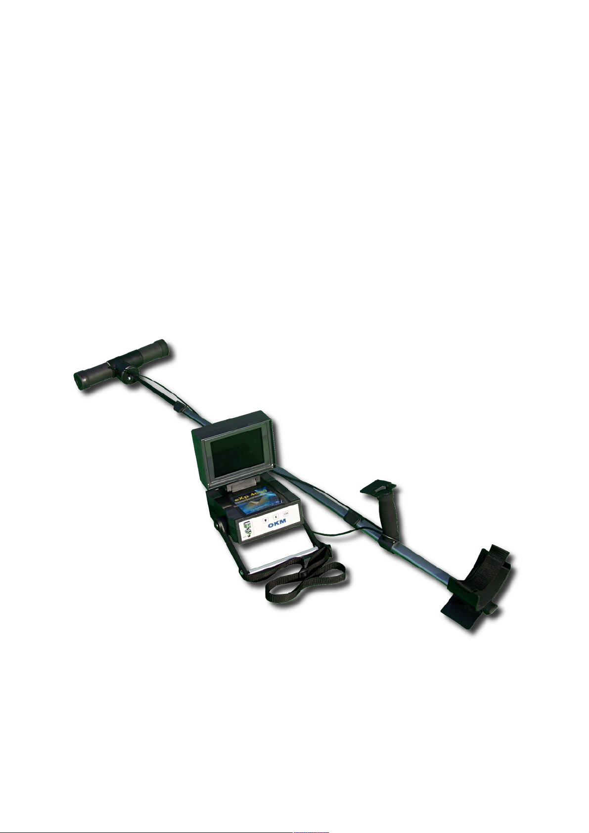
you for your purchase of the eXp 4000.
The eXp 4000 detector works on the principle of Electro-Magnetic Signature Reading (EMSR). Besides
the detection of metallic objects this device is also capable of detecting natural features of the earth like
formations of strata, cavities, voids, faults, ground water and other non-metallic objects. Then of course
this equipment is best suited at detecting sepulchers, treasure, buried utilities, tanks and the like.
The eXp 4000 is able to locate, document and analyze buried objects within various structures and
vessels non-intrusively without having to excavate the area. Using EMSR is particularly useful in areas
where detection is a must and excavation is not possible. The facile and flexible handling of the eXp
4000 can easily and quickly give reproducible results.
With our team of specialists we guarantee that our products are under recurrent control. Our specialists
try to implement new developments in terms of further quality improvements for you.
By purchasing or using one of our products, we cannot guarantee that during the course of your
research that you will be successful and have a find. The recognition of hidden and buried objects
depends on a huge number of factors. As you well may know there are different soil types all over the
world with different levels of natural attenuation. Variable soil properties can and will hamper and alter
ultimate scan measurements. Areas where there is an extreme amount of ground water, varying clays,
sands and wet soils making scanning more difficult and may reduce the maximum depth capabilities of
any and all detection equipment, regardless of make or model.
For more information regarding where this equipment has been used and operated, please visit our web
site. Our equipment is constantly being tested and when improvements or upgrades are available, we
will list them also on our web site.
It is necessary for our company to protect our developments and all of the information learned during
the “Research and Development” phases in creating our technology. We strive to stay within the given
framework of legislation, patents and trademark registration.
Please take your time to read this User Manual and familiarize yourself with the operation, functionality
and how to utilize the eXp 4000. We also offer training for your equipment in our factory and on-site. We
strive to maintain worldwide dealer network for assistance and support. Please visit our web site for
more information.
OKM Ortungstechnik GmbH
www.okmmetaldetectors.com

Introduction 9
1.2 Important Notes
Prior to using the eXp 4000 and its accessories, please read these operating instructions carefully.
These instructions give information on how to use the detector and potential sources where precautions
should be taken.
The eXp 4000 and its accessories serve for the analysis, documentation and detection of sub-surface
anomalies and ground disturbances. The recorded data of the ground structure will be transmitted to a
PC to give a visual representation using our proprietary software program. Any additional notes to the
software should be observed. Please read the user manual of the software!
1.2.1 General Notes
Being an electronic device, the eXp 4000 has to be treated with caution and treated with care as with
any electronic device. Any failure to observe the safety precautions given or any use for purposes other
than the ones it is designed for may result in damage or destruction of the processing unit and/or its
accessories or connected components.
The device has a built in anti-tampering module which will destroy the unit if it is improperly opened.
There are no end user serviceable parts on the inside of the unit.
1.2.2 Possible Health Hazards
If used properly this device normally does not pose any health hazards. According to current scientific
knowledge, the high-frequency signals are not harmful to the human body on account of their low power.
1.2.3 Surrounding Area
When moving this unit from a cold place to a warmer place, watch out for condensation. Do not
immediately operate the unit until any possible condensation could have evaporated. The unit is not
weather proof and water or condensation can destroy the unit.
Avoid strong magnetic fields, which may occur in places where there are large electric motors or
unshielded loudspeakers. Try to avoid using this equipment within 50 meters (150 ft) of this type of
equipment.
Metallic objects on the ground such as cans, tin, nails, screws or debris can influence your scan data and
present negative results regarding your scan data. Also it is a good habit to remove any metallic objects
off of your person like cellular telephones, keys, jewelry, etc... Do not wear steel toe boots.
1.2.4 Voltage
The power supply should not be outside the indicated range of values. Use only approved chargers,
batteries and rechargeable batteries which are included in the scope of delivery.
Never use the 115/230 Volt mains supply.
OKM Ortungstechnik GmbH
www.okmmetaldetectors.com

10 Introduction
1.2.5 Data safety
Data errors can occur if:
• the range of the sender module has been exceeded,
• the power supply of the device or the batteries are too low,
• the cables are too long,
• the unit is operating to close to devices which sends out disturbances or
• atmospheric conditions (electrical storms, lightning, etc...).
1.3 Maintenance and Services
In this section you will learn how to maintain your measuring instrument with all included accessories to
keep it in good condition a long time and to get good measuring results.
The following list indicates what you absolutely should avoid:
• penetrating water
• strong dirt and dust deposits
• hard impacts
• strong magnetic fields
• high and long lasting heat effect
To clean your device please use a dry soft rag. To avoid any damage you should transport the device and
accessories always in the appropriate carrying cases.
Prior to using your eXp 4000 please be sure that all batteries and accumulators are fully charged. Also
allow the batteries to completely discharge before recharging them, regardless if you are working with
the external battery or with internal accumulators. This way your batteries will have a long and durable
life.
To charge the external and internal batteries, use only the approved chargers which are part of
our scope of delivery.
1.4 Danger of Explosion during Excavation
Unfortunately, the last two world wars also made the ground in many places of the world a potentially
explosive scrap heap. A host of those lethal relics are still buried in the ground. Do not start digging and
hacking for an object wildly when you receive a signal of a piece of metal from your device. Firstly, you
might indeed cause irreparable damage to a truly rare find, and secondly, there is a chance that the
object reacts in an insulted way and strikes back.
Note the color of the ground close to the surface. A red or reddish color of the ground is an indicator of
rust traces. As regards the finds themselves, you should definitely pay attention to their shape. Curved
OKM Ortungstechnik GmbH
www.okmmetaldetectors.com

Introduction 11
or round objects should be a sign of alarm, especially if buttons, rings or little pegs can be identified or
felt. The same applies to recognizable ammunition or bullets and shells. Leave that stuff where it is, do
not touch anything and, most importantly, do not take any of it home with you. The killing machines of
war made use of diabolical inventions such as rocker fuses, acid fuses and ball fuses. Those components
have been rusting away in the course of time, and the slightest movement may cause parts of them to
break and be triggered. Even seemingly harmless objects such as cartridges or large ammunition are
anything but that. Explosives may have become crystalline over time, that is, sugar-like crystals have
formed.
Moving such an object may cause those crystals to produce friction, leading to an explosion. If you come
across such relics, mark the place and do not fail to report the find to the police. Such objects always
pose a danger to the life of hikers, walkers, farmers, children and animals.
OKM Ortungstechnik GmbH
www.okmmetaldetectors.com


2 Install/Uninstall USB drivers on Windows
CHAPTER 2
Install/Uninstall USB drivers on
Windows
In this chapter you will learn how to install the USB drivers, that are necessary to transfer data from the
machine to your computer software. Please make sure to read the proper section appropriate to your
Windows operating system.
14 Install/Uninstall USB drivers on Windows
2.1 Windows XP
The instructions in this section are only valid for Windows XP.
2.1.1 Install USB drivers on Windows XP
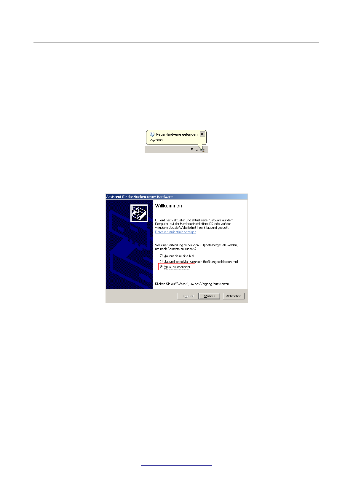
The installation of the USB drivers in Windows XP is relatively simple. After you have connected the
device with your computer, switch it on and the message from figure 2.1 appears on your screen.
Illustration 2.1: Install USB drivers: Windows XP, Step 1
If your Windows XP has Service Pack 2 installed, you will see the dialog from figure 2.2 if Windows
Update has to search for drivers up to date. Mark entry
"No, not this time"
and click on
Next
.
Illustration 2.2: Install USB drivers: Windows XP, Step 2
In other versions of Windows this window should not appear.
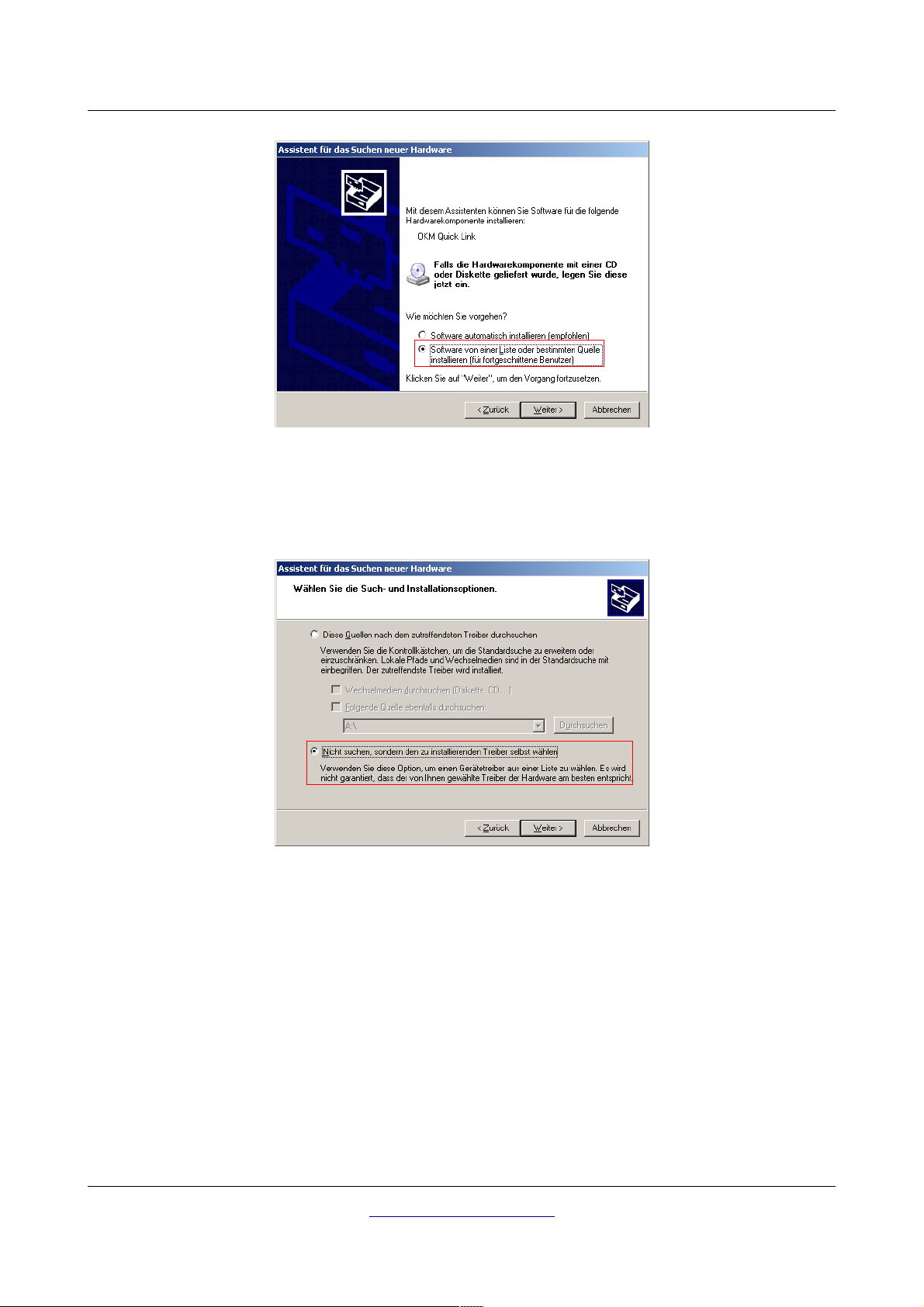
In the following dialog window like figure 2.3 select the entry
Next.
OKM Ortungstechnik GmbH
www.okmmetaldetectors.com
"Install software from a list …"
and click
Install/Uninstall USB drivers on Windows 15
Illustration 2.3: Install USB drivers: Windows XP, Step 3
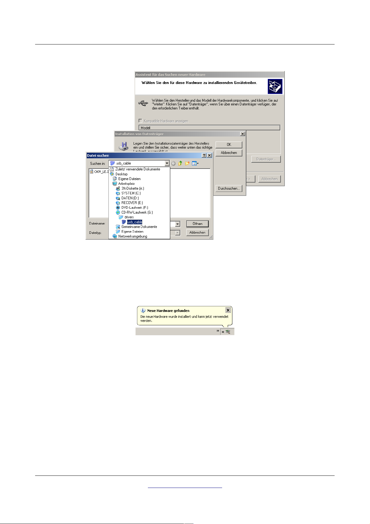
In the next dialog window from figure 2.4 mark the entry No search, select driver individually and click
on Next.
Illustration 2.4: Install USB drivers: Windows XP, Step 4
Another window will open, represented in figure 2.5, where you have to select the driver file. Therefore
click on Data carrier. ... Immediately another window appears where you click on the button Search ...
Then select the file OKM_LE.INF, which you can find in the directory \drivers\usb_cable of your
software CD. Afterwards you have to click on Open, OK and Next, to start the installation of the files.
OKM Ortungstechnik GmbH
www.okmmetaldetectors.com
16 Install/Uninstall USB drivers on Windows
Illustration 2.5: Install USB drivers: Windows XP, Step 5
After successful installation of the driver a message like in figure 2.6 will appear on your computer
screen. Now the drivers of your device are installed and you can transfer data to your PC.
Illustration 2.6: Install USB drivers: Windows XP, Step 6
OKM Ortungstechnik GmbH
www.okmmetaldetectors.com
Install/Uninstall USB drivers on Windows 17
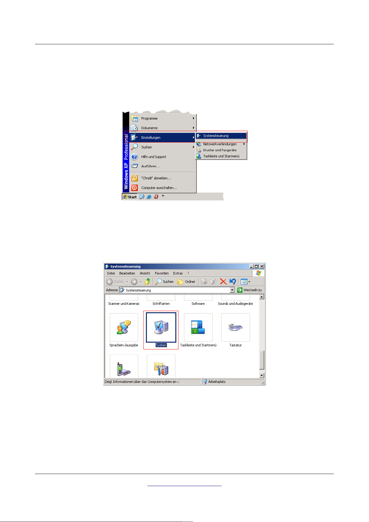
2.1.2 Uninstall USB drivers on Windows XP
If you need to delete the USB drivers from your operating system because of a wrong installation, please
open the device manager of Windows XP. Therefore please click on Start > control panel, like
represented in figure 2.7.
Illustration 2.7: Uninstall USB drivers: Windows
XP, Step 1
After that a dialog like in figure 2.8 appears. There you can find the entry system and click twice on it.
Illustration 2.8: Uninstall USB drivers: Windows XP, Step 2
The dialog from figure 2.9 appears on your screen. Click on the tab hardware and after that the button
device manager.
OKM Ortungstechnik GmbH
www.okmmetaldetectors.com

18 Install/Uninstall USB drivers on Windows
Illustration 2.9: Uninstall USB drivers: Windows
XP, Step 3
A list of devices like in figure 2.10 will be represented. There you can find the entry USBController. By
clicking the plus symbol next of this entry, all available USB devices will be shown.
Illustration 2.10: Uninstall USB drivers: Windows XP, Step 4
Mark the device which you like to delete, which means "eXp 4000. Additionally the device may be listed
as “OKM Quick Link”. Then click on the button. Alternatively you can select the entry Uninstall in the
menu Action.
OKM Ortungstechnik GmbH
www.okmmetaldetectors.com

Install/Uninstall USB drivers on Windows 19
Illustration 2.11: Uninstall USB drivers:
Windows XP, Step 5
The dialog from figure 2.11 appears. Click there on the button OK. Now all drivers will be deleted from
your computer. If needed you can now install the USB driver again correctly.
OKM Ortungstechnik GmbH
www.okmmetaldetectors.com

20 Install/Uninstall USB drivers on Windows
2.2 Windows Vista
The instructions in this section are only valid for the Windows Vista operating system.
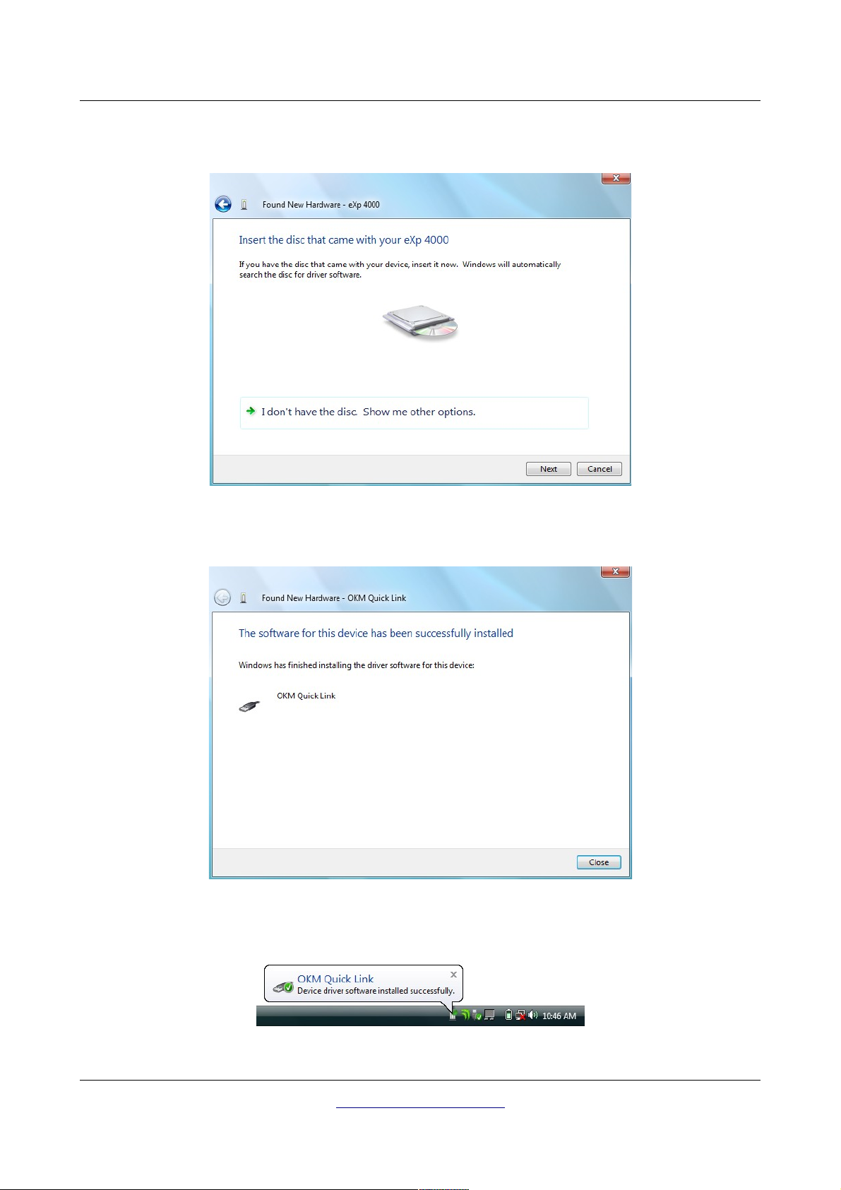
2.2.1 Install USB drivers on Windows Vista
The installation of the USB drivers in Windows Vista is relatively simple. After you have connected the
device with your computer, switch it on and the message from figure 2.12 appears on your screen. Click
on Locate and install driver software (recommended).
Illustration 2.12: Install USB drivers: Windows Vista, Step 1
At the next window, shown in figure 2.13, click on Don't search online.
Illustration 2.13: Install USB drivers: Windows Vista, Step 2
OKM Ortungstechnik GmbH
www.okmmetaldetectors.com
Install/Uninstall USB drivers on Windows 21
When the window from figure 2.14 is visible, insert the software CD with the USB drivers into your CD
drive and click on the Next button. Windows will now search for the correct USB drivers automatically.
Illustration 2.14: Install USB drivers: Windows Vista, Step 3
When the installation has finished the completion screen from figure 2.15 is displayed. Press Close to
close this window.
Illustration 2.15: Install USB drivers: Windows Vista, Step 4
Now you have completed the installation of the USB drivers in Windows Vista, which will be confirmed
by presenting the message from figure 2.16.
Illustration 2.16: Install USB drivers: Windows Vista, Step 5
OKM Ortungstechnik GmbH
www.okmmetaldetectors.com
22 Install/Uninstall USB drivers on Windows
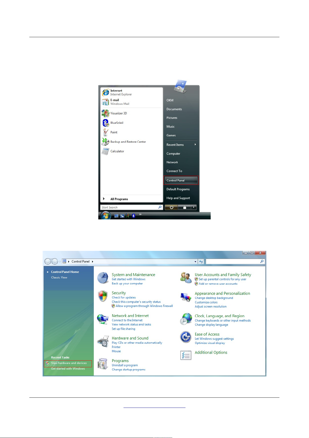
2.2.2 Update USB drivers on Windows Vista
If you need to update the USB drivers on your operating system or the initial installation failed, please
open up the Device Manager of Windows Vista. Therefore press the Windows start button and click on
Control Panel.
Illustration 2.17: Update USB drivers on Windows Vista, Step 1
At the next screen, shown in figure 2.18, select View hardware and devices which can be found on the
bottom of the left sidebar.
Illustration 2.18: Update USB drivers on Windows Vista, Step 2
OKM Ortungstechnik GmbH
www.okmmetaldetectors.com
 Loading...