

Okina USA SDNR-8700 User Manual
Copyright © 2013. All Rights Reserved.
** Replacing SDNR-8630
PAL version also available
SDNR-8700
D
igital Noise Reduction
700 TVL DNR Super Low Lux OSD
ICR Box Camera
USER MANUAL
* Lens not included
FEATURES
• 700 TV Lines
• 1/3” Sony Exview CCD II
• Digital Noise Reduction (DN R) -
Dramatically reduces both random and fixed
noise. It also reduces DVR disk space usage by up to 70%.
• 0.00039 (Sens-up, 256 X) / 0.1 Lux (50 IRE @ F1.4)
• Built-in Microphone RCA Output
• RS485 Output for OSD Control
• 330mA
• Dual Power 12V D C / 24V AC
Optional External IR
SDNR-8IR14
See page 22 for details

2
Disposal of Old Electrical & Electronic Equipment (Applicable in the
European Union and other European countri es with separat e collection
systems).
This symbol on the product or on its packaging indicates that this product shall not be
treated as household waste. Instead it shall be handed over to the applicable collection
point for the recycling of electrical and electronic equipment. By ensuring this product is
disposed of correctly, you will help prevent potential negative consequences for the
environment and human healt h, w hich could otherwise be caused by inappropriate
waste handling of this product. The recycling of materials will help to conserve natural
resources. For more detailed information about recycling of this product, please contact
your local city office, your household waste disposal service or the shop where you
purchased the product.
CAUTION
1. Never point the camera toward the sun
Do not expose the lens directly to the sun or to strong light as this may damage the
pick-up device.
2. Handle this camera with care
Avoid any shock or bumping of the camera. Improper handling could damage the
camera.
3. Requires a proper operating environment
This camera is designed for indoor use. The allowable temperature range for
operation of this camera is betw een 14°F ~ 122°F / -10°C ~ 50°C.
Please read the Manual before attempting to use this product.
Specifications and appearance are subject to change without notice.

3
4. Clean the front face or lens
It is recommended th at the s urface be cl eaned ev ery 3~6 months. Cle aning sh ould b e
done by using a chamoi s, a v e r y fine s oft c loth, lens tissue, or cotton tipped app li cato r
and ethanol to carefully remove any fingerprint or dust.
5. Check the power source voltage
The power source voltage should be within the specified range. (Camera must meet
the specifications). Camera must be connected to a surge protector at all times.
6. Objects and liquid entry
Never push objects of any kind into this camera as this may touch dangerous voltage
points of short out p arts that co uld result in a fir e or elec tri c shock. Never spi ll any kind
of liquid on the video product.
7. Servicing
Do not attempt to service this video product by yourself as opening or removing
covers may expose you to dangerous voltage or other hazards. Refer all service to
qualified servicing personnel.
8. Damage requiring service
Unplug this video product from the wall outlet and refer service to qualified servicing
personnel under the following conditions:
a. When the power supply cord or plug is damaged.
b. If liquid has been spilled, or objects have fallen into the video product.
c. If the video product has been exposed to rain or water.
d. If the video product has been dropped or the cabinet has been damaged.
e. When the video product exhibits a distinct change in performance.
LI MITE D WARRAN TY
OKINA USA products are covered under warranty for one year from the date of
purchase. The warranty will automatically be voided if any of the following occurs:
1. Camera sticker is removed
If the camera sticker is removed, we will not be able to confirm any information
regarding when and where the product was purchased. We have no other way to
verify the purchase record without the serial number on the camera sticker; therefore,
it should not be removed.
2. Camera is modified in any way
If the camera is scratched, damag ed, or modif ied in a man ner not descr ibed in this
manual, the warranty will be voided immediately. It is the customer’s responsibility to
keep the camera in good condition.
3. Video or power cable is cut
The video cable and the power cable should not be tampered with. Cutting or
modifying of the cables will result in termination of the warranty.
4
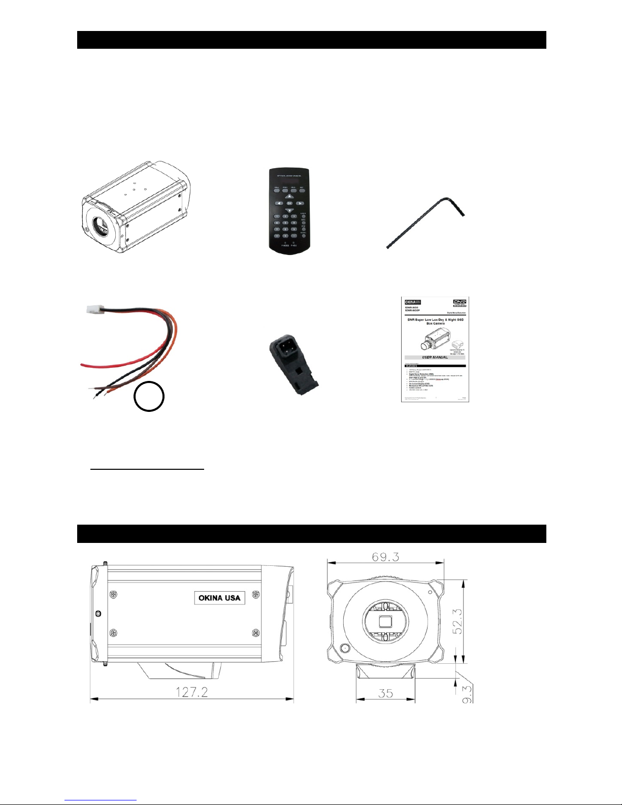
PACKAGE CONTENTS
A. One (1) DNR Vandal Proof Box Camera with power/video cable
B. One (1) Remote Control
C. O ne (1) Allen Wrench
D. One (1) Motion Relay Output Wire
E. One (1) IRIS Connector
F. One (1) User Manual
* For any returns, please include all components listed above with original packaging in
Resalable Condition. Absolutely No Returns will be accepted if any component is
missing/damaged.
DIMENSION
A. B. C.
D. E. F.
Refer to #4 on
page 5 for details
4
Unit: mm
5
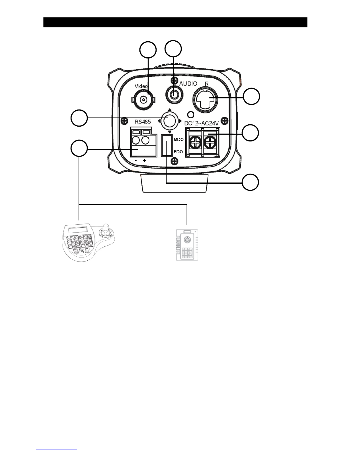
REAR PANEL
1. Video Output
2. Audio Output
3. RS485, +/- – See page 12 for PTZ controller key combination to call up OSD
menu and page 10 for wire & cable
4. MDO, Motion Detect Relay Output
a. Black & Brown = for External Alarm Device.
Set up on OSD Menu: Special Motion Motion View: On/Off
See page 11 for OSD setting and page 8 for application diagram
b. Red & Orange = not working for this model
5. 12V DC~24V AC, dual power
6. External IR (optional) – See page 15 for more details
7. On-Screen Display (OSD) Control
1 3 5 6 7
4
2
OR
PTZ-KB250
PTZ-KB050X

6
OPERATION
Once camera is inst alled, ma ke sur e the fo cal len gth and foc us is pr oper ly adjuste d be fore
configuring the camera through on-screen display (OSD).
The Main menu provides access to the camera configuration options. The on-screen
display (OSD) is only available in multi languages, such as English, Korean, Traditional
Chinese, Simplified Chinese, Japanese, Russian, French, Spanish, Italian, Portuguese,
Dutch, German, Polish, Turkish, Hebrew, Arabic.
Program the camera by attaching a standard video monitor to the system.
OSD Button Menu:
Setup Menu Description
Menu Item
Description
Lens
Defines the lens brightness and iris speed
Exposure
Defines the method of iris control
Backlight
Defines the highl ight co mpe ns ation (HLC)
and backlight compensation (BLC) set up
White Bal
Defines the white balance (WB) set up
Day & Night
Defines the day/night (D/N) set up
Smart 3DNR
Defines the digital noise reduction set up
De-fog
Defines the defog set up
Function
Defines motion detection, privacy, digital
effect, image adjustment, auto focus,
language and OSD color set up
Exit
Exits the menu and returns to live mode.
Save changes made.
MAIN MENU
1.LENS DC↵
2.EXPOSURE ↵
3. BACKLIGHT OFF
4. WHITE BAL AWB
5.DAY&NIGHT AUTO↵
6.SMART 3DNR ON↵
7.DE-FOG OFF
8.FUNCTION ↵
9.EXIT SAVE↵

7
To access the Setup menu:
1. Press the OSD control pad (Enter) or Coaxial Control Enter button to access
the Main menu and its submenus.
2. Push the pad up, down, left and right or Coaxial Control TELE,WIDE, NEAR,
and FAR button to move between menu options.
3. Press the OSD control pad Coaxial Control Enter button to select an option.
4. When in a sub menu, select “Return to return to the previous menu.
5. To exit the Main menu, move the cursor to Exit at the bottom of the screen and
press Enter. A l l chan ges are s av ed.
SELECT THE LENS
In the Setup menu, go to Lens and select the type of lens used with the camera. Select
DC to adjust the lens setting manually,
1. Brightness: Select the Brightness level, value from 1 to 100.
2. Iris Speed: Select the iris spe ed, valu e fro m 1 and 5.
EXPOSURE
In the Setup menu, go to E x posure and pre ss Ent er, the below figure shows the dif fer ent
options available:
1. Shutter:
1/60: Fixed value
MANUAL: defines manual shutter value. Select a higher value to see
movement and a lower value to see clearer images. The values range from
1/60 to 1/100000.
FLK: flicker mode avoids interference from light sources.
AUTO: the camera sets the optimum shutter speed. User can define the
maximum shutter speed in AUTO mode. The values range from FLK to
1/100000.
DC LENS
1. BRIGHTNESS 60
2. IRIS SPEED 2
3. RETURN RET↵
EXPOSURE
1.SHUTTER 1/60↵
2. AGC MIDDLE
3. SENSUP AUTO
↵

8
2. AGC: Adjust the maximum automatic gain control level, used in low-light
conditions with the iris fully open. The values range from OFF to High.
3. SENS-UP: The setting refers to the amount of light being allowed to load on
the sensor from 2-t imes the "n or mal " light up to 256-times the "normal" light.
This method can allow for brilli ant, clear color i mages to b e taken in n early total
darkness. The values range from x2 to x256.
SET BACKLIGHT
In the Setup menu, go to Backlight and select the options (DWDR, HLC, BLC, or OFF)
to be modified in the menu. Note that this can be set up only if DAY&NIGHT is on
COLOR mode.
DWDR:
Digital Wide dynamic range (DWDR) allows you to see details of objects in shadows or
details of objects in bright areas of frames that have high contrast betw een light and
dark areas such as the headlights of a passing car.
1. Low level: Set the low level of DWDR. The values range from 0 to 15
2. High level: Set the high level of DWDR. The values range from 0 to 15
BLC:
BLC (backlight compensation) can improve image quality when the background
illumination is high. It prevents the object in the center from appearing too dark.
1. Value: Set the value level of backlight compensation. The values range from
low to high
2. Area: Set the area of the backlight compensation by position and the size. If
need to define two backlight areas, please select DOUBLE
3. Default: Reset to default the backlight compensation setting and area.
DWDR
1. LOW LEVEL 5
2. HIGH LEVEL 3
3. RETURN RET↵
BLC
1. VALUE MIDDLE
2. AREA SINGLE↵
3. DEFAULT ↵
 Loading...