

Okina USA SDN-6420, SDN-6420P, SDN-6520, SDN-6520P Operating Manual
1
OPERATING MANUAL
DIGITAL COLOR CCD CAMERA
OKI USA DAY & NIGHT SERIES
Model SDN-6420 SDN-6420P 420 TV LINE
Model SDN-6520 SDN-6520P 520 TV LINE
Power
24VAC/12VDC 85V~265VAC
1/3” SONY Super HAD CCD
1 General
This color CCD camera employs 1/3 inch charge coupled imaging device with
470/410 k or 310/270 k picture elements. It is equipped with advanced Digital
Signal Processor for processing the video signal to provide high color
reproduction, sharp and stable picture.
2 Features
1. Color & B/W mode: Daytime color and user selectable color or b/w
mode when under low lux condition.
2. Resolution: 420/520 TV lines of horizontal resolution.
3. Low lux: BY employing high sensitivity image sensor and low noise
circuit design produces 0.5 lux and signal-to-noise ratio of 48 dB.
4. White Balance: The wide range of Auto Wide balance(AWB) and Auto
Tracing White balance (ATW) allow the camera to adjust automatically
the tone according to the color temperature of the light source
illuminating the subject.
5. Back Light Compensation: Smart digital control Auto BLC, ensure for
use against any unusual lighting conditions.
6. Auto Exposure System: Advanced Auto Exposure System for both fix
iris and auto iris lenses control the amount of light to ensure it is always
optimized.
7. Internal or Line-lock external sync.
2
DC VIDEO
VIDEO OUT
PL
AC 24V
DC 12V
V-phase
BLC
ATW
AG C
VIDEO OUT
PL
INT
FL OFF
AES
AE
AC85 V~2 65V
V-phase
AG C
ATW
L.LUX
INT
AES
BLC
FL OFF
AE
BLCOFF
SUPAGC
AWB
L.L.
FLON
ME
AI
SUPAGC
L.LUX
L.L.
AWB
BLCOFF
FLON
AI
ME
B/WCOLOR
B/W
L.LUXL.LUX
COLOR
V-phase
VIDEO OUT
PL
L.LUX L.LUX
COLOR B/W
NC
AG C
ATW
BLC
AES
FL OFF
AE
SUPAGC
BLCOFF
AWB
NC
ME
FLON
AI
DC 12V
DC VIDEO
DC L EV EL
DIGITAL
DCBA
EF
HG
J
K
I
L
M
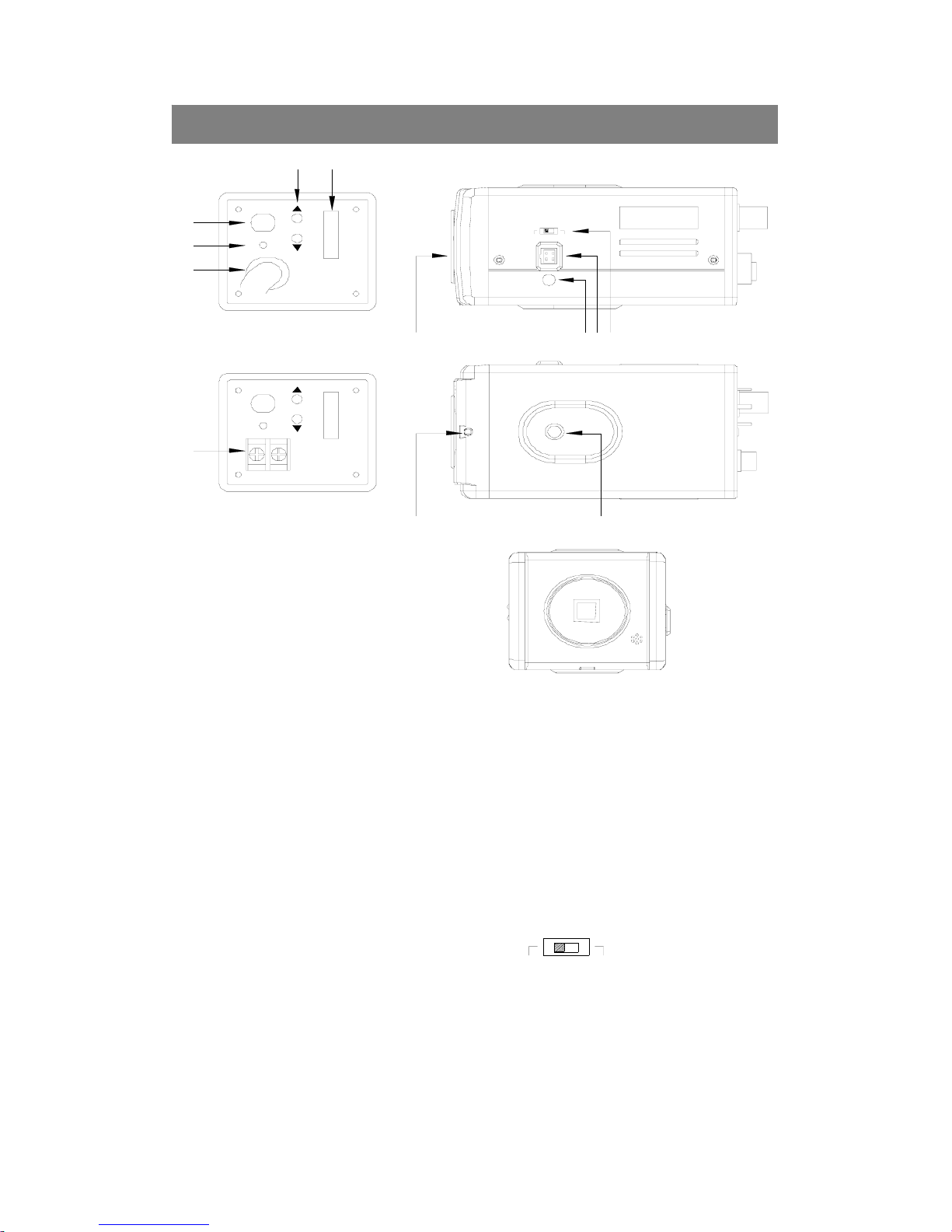
3 Name of parts and functions
A. C(CS)mount adapter
When using a CS mount lens, remove the C mount ring.
B. DC lever Adjuster(VR)
For DC drive auto iris lens driving level adjustment; in order to obtain
correct exposure light.
C. Auto iris lens connector(MINI JACK) See 3-1 auto-iris connector.
D. Video/DC auto-iris lens selector
DC—For DC drive lens
Video—For Video drive lens
E. Flange focal lock screw
F. Holder screw hole
Standard photographic pan-head screw size(1/4”-20)
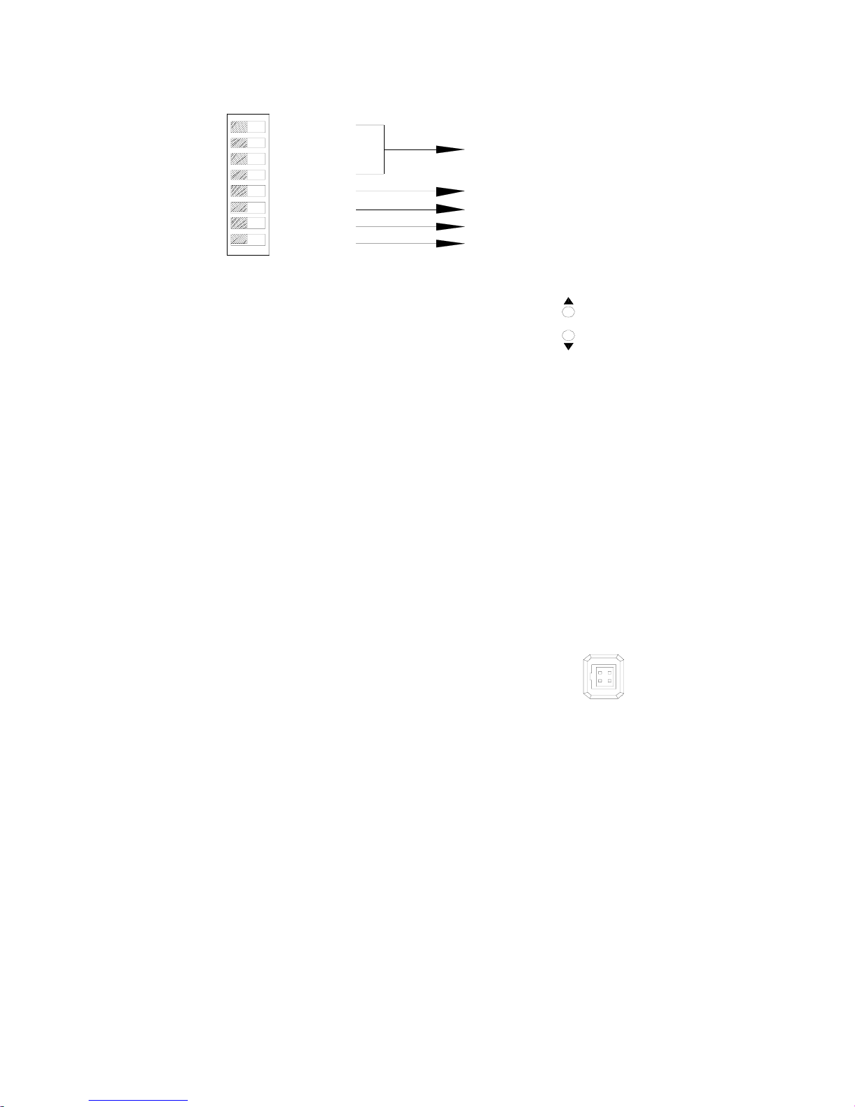
G. Dip Switch
COLOR
B/W
AGC
L.LUX
INT
ATW
FLOFF
BLC
AE S
AE
SUPAGC
L.L.
L.LUX
AWB
BLCOFF
FLON
AI
ME
AG C M OD E
SY NC MODE
LOW LUX COLORMONO OP TION
WB MODE
AE S ETTING
V-phase
H. Phase Adj.
Line-lock Phase Adj.(Line-lock model)
I. Video output terminal(BNC)
This connector is used to connect with the VIDEO IN connector of monitor.
J. Power pilot LED
K. AC85V~265V Power Cord
L. DC 12V or AC24V/DC 12V Block Terminal
3.1 Auto Iris Lens Connector
● Use the accompanying auto iris lens control connector plug.
For auto iris lens with built-in EE amp.(VIDEO Type)
Set the lens selector switch to “Video” position.
1
2
3
4
Connector cable leads
1.Red----power 2.NC
3.White----video 4.Black----shielded
For auto iris lens without EE amp.(DC Type)
This is the view from external of camera
Set the lens selector switch to “DC” position.
Connector cable leads
1.Damping coil(-) 2.Dampling coil(+)
3.Driving coil(+) 4.Driving coil(-)
Connect the leads as shown above; refer to the instructions of the lens.
3
 Loading...