

Okina USA HUB-TF, HUB-TFHB Operational Manual
1
HUB-TF
HUB-TFHB
FEATURES
Pl ease read the Operational Manual
before attempting to use this product.
Operational Manual
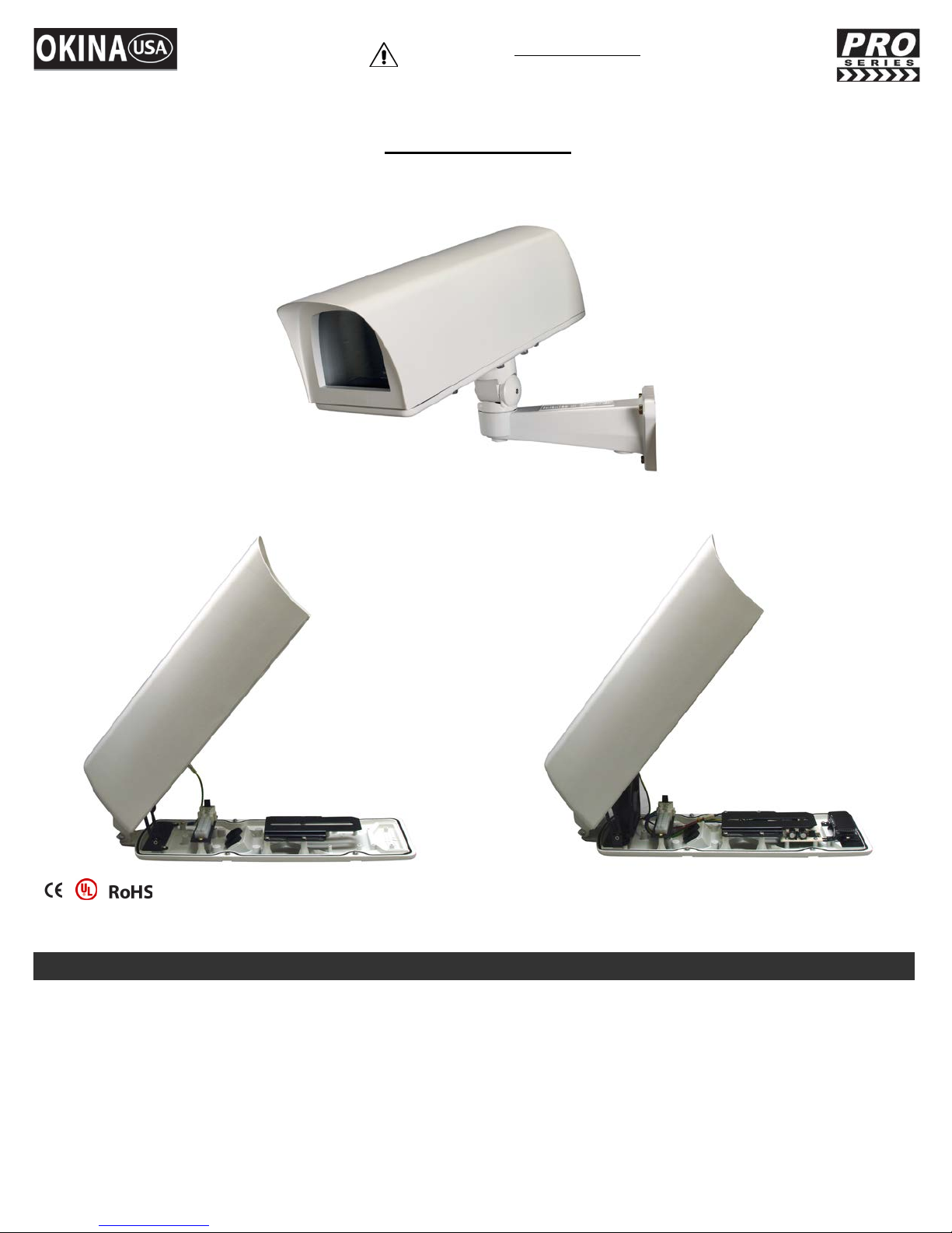
Pr o fessio nal C amera Housi ng - Front Opening
80
HUB-TF HUB-TFHB
* UL certification onl y refers to the power converter and the power module
Constru cted from die-cast aluminum alloy and is powder coated with stove finish
IP67 Rating – des igned and manufactured to the highest t echnical sta nda rd with environm e nt al protection
Fully-Cable Manag ed Brack et
Uses p rofessi o nal rust-proof stainless steel screws
Includes Heater & Blow er for H UB-TFHB
24V AC, 40VA
HUB-TF_HUB-TFHB_rev042709
2
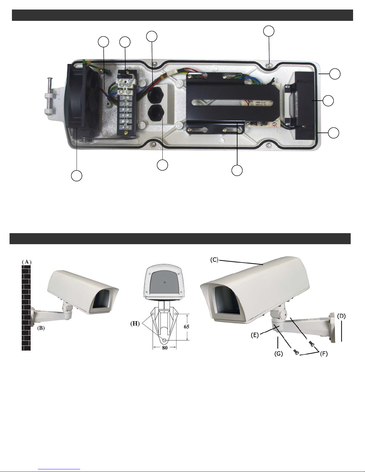
PART DESCRIPTION
MOUNTING CONFIGUR ATION
8
5
9
7
1
2
3
6
10
4
1. Heater (Only for HUB-TFHB) 6. Cable conduits PGB11 x2
2. Heat S hi el d (Only for HUB-TFHB) 7. C ap tiv e retai n in g scr ews x 4
3. Therma l cont rol board 8. Heater & blower wires, Ground wire
4. Camera mounting platform 9. Ground Wire
5. Termina l bloc k as se mbly 10. B lower (Only for HUB-TFHB)
1. Us e the re ar section of t he Mount ing Bracke t (D) as a template for marking the position on the wall of the
Mo unting Holes (H). Remove & dr il l to pattern req ui red.
2. Attach the Mounti ng Bracket arm to the wal l using the raw pl ugs and screws provi ded.
3. Feed cabl es from the mai n Housing (C) through the ho le of M o unt ing Plate (E) on the Mounti ng Bracket (D),
then feed cabl e again to conceal ed channel in side the Mounti ng Bracket throughout wal l outl et (A) or bracket
outlet (B).
4. Attach the mai n Housing (C) to the Mo unt ing Plate (E) of Bracket with 4 of 1/4" x 14.7mm Trilobular screws (F)
provided.
5. Release Screw (G) on the Mounting Bracket to pan and tilt the Housing. Positi on the Housing as required for the
correct Camera coverage then tighten both Screws to secure.
HUB-TF_HUB-TFHB_rev042709
3
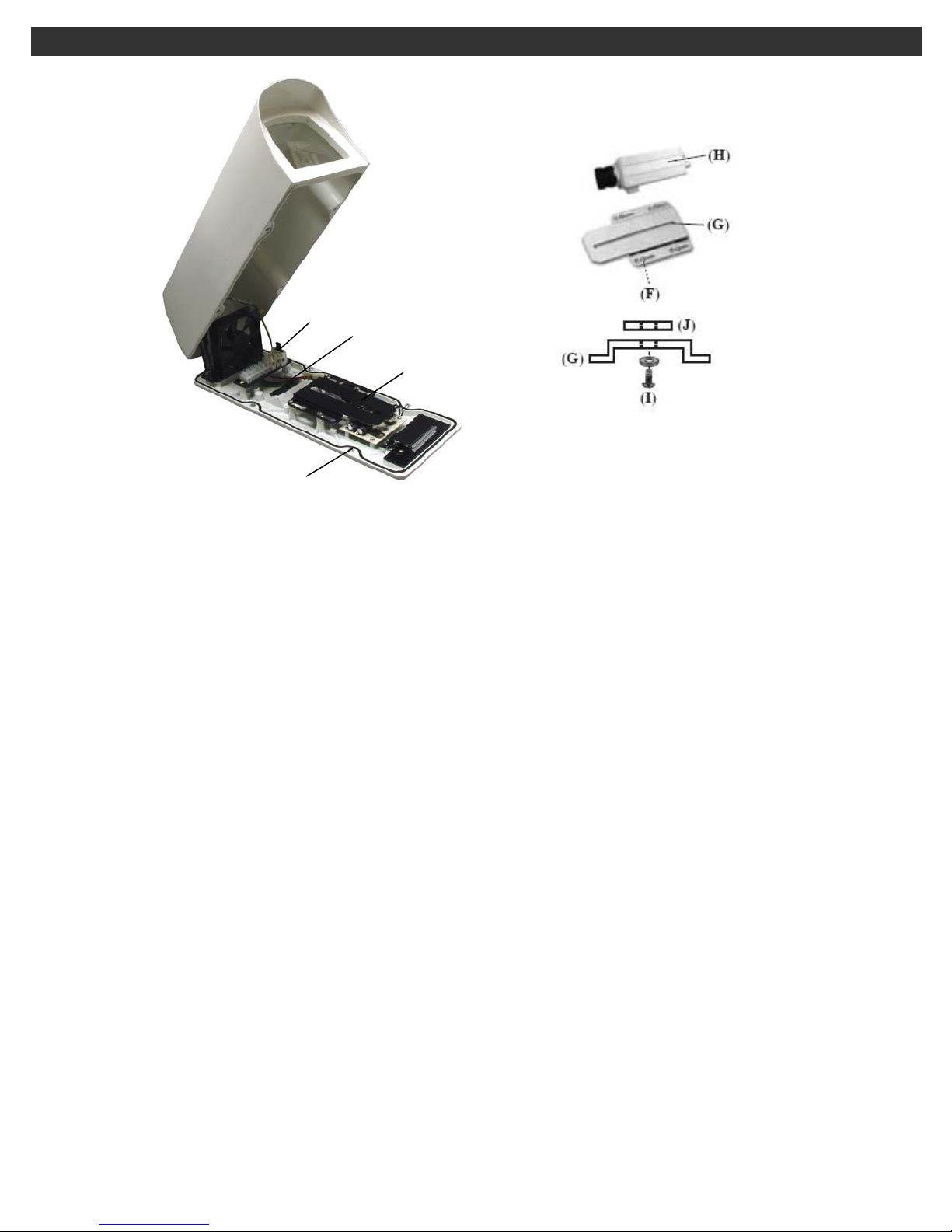
FITTING INSTRUCTIONS
(A)
(B)
(C)
(D)
(E)
(F)
1. Unscrew the 3 capti ve Retai ning Screws (C) and remove the Housing Cover (A) from the Housing Base (B).
2. Release the 4 Keyho le Screws (F) and the n slide a nd withdraw t he Camera Plat f o rm (G) from the Housi ng
Base (B).
3. Mount the Camera (not included) (H) onto Platform (G) using the 1/4" UNC Screw (I) Suppli ed, ensuri ng that the
Insulatio n P a d (J) i s mounted between the Platfor m and the Camera. Alw ays check that the Camera is fi r ml y
attached to the Pl atform.
4. Conn ect t he Camera / Heater p ower cabl e to th e rear Termi n al Bl ock (E) thro ugh the first Cable Conduit (D)
referring to the circui t diagram s hown in t he WIRING DIAGRAM se ction of the manual for the terminal
designations.
5. Conne c t the video c able t o the C a mera through the second Cable Conduit (D).
HUB-TF_HUB-TFHB_rev042709
 Loading...