

Okina USA HDRR-04, HDRR-16, HDRR-08 Quick Setup Manual
MADE IN TAIWAN DV-18 / DV-19 / DV-20
Copyright © 2014 OKINA USA. All rights reserved. R201405-V09
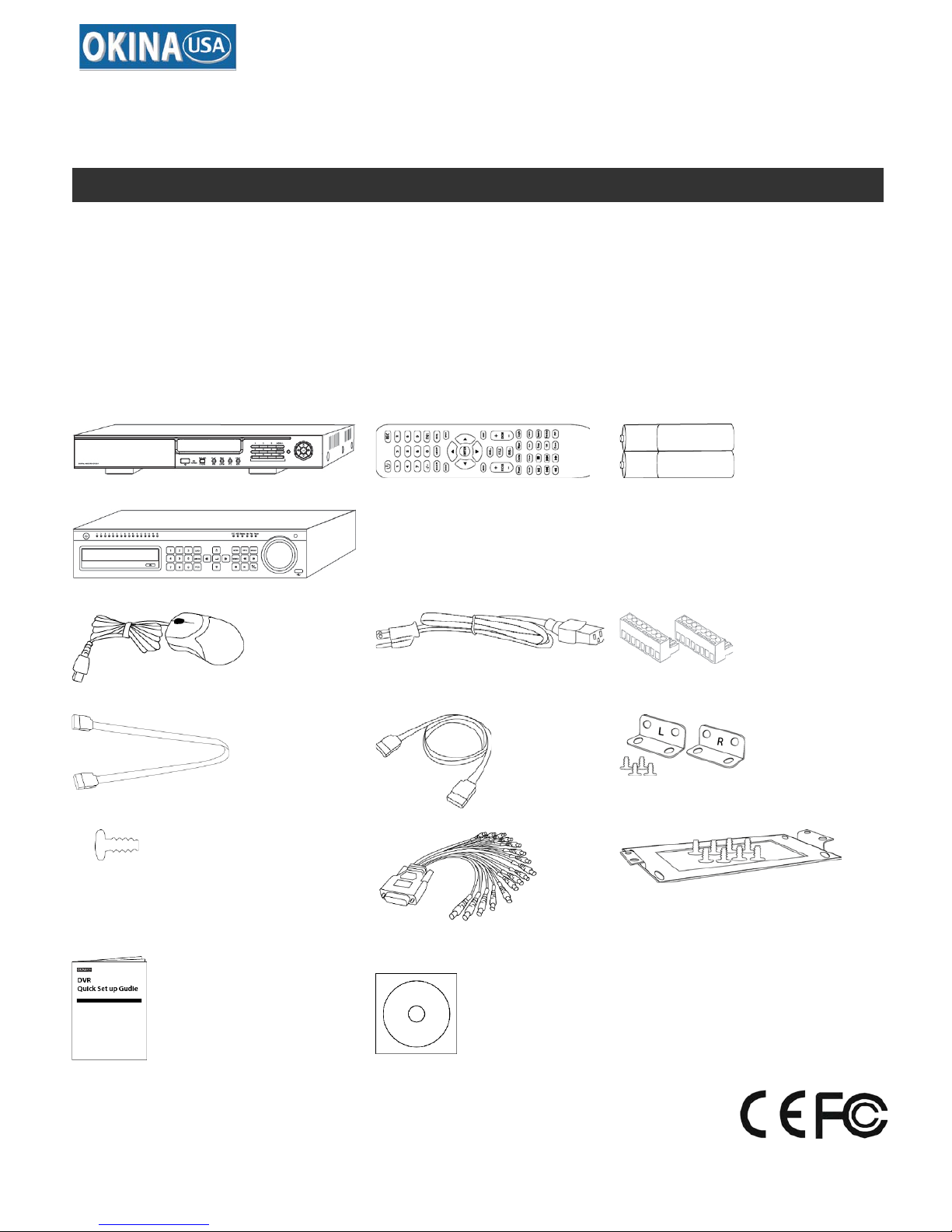
PACKAGE CONTENTS
A.
B.
C.
4 / 8 CH.
16 CH.
D.
E.
F.
x 2 (4 / 8 CH.)
x 4 (16 CH.)
G.
H. Inside the DVR
I.
x 2
x 10
x 2 (16 CH.)
J.
K.
L.
x 32 (16 CH.)
x 1 (16 CH.)
x 1 (16 CH.)
M.
N.
*Notes:
Any Return Must Include All Components.
Additional charges apply for any missing
components. A UPS Battery Backup
System is highly recommended to avoid
power failure restoration damage to Hard
Drive & Motherboard.
Please read this Quick Setup Guide before installation.
**Quick Setup Guide & User’s Manual are subject to change without notice.
A.
One (1)
HDRR-04 / HDRS-08 / HDRR-16 DVR
I.
Two (2)
Rack Mount Ear w/ Screws – HDRR-16
B.
One (1)
Remote Controller
J.
Thirty-two (32)
Hard Drive Screws – HDRR-16
C.
Two (2)
AAA Battery for Remote Controller
K.
One (1)
DB15 to 16-CH Audio Cable –
HDRR-16
D.
One (1)
USB Mouse
E.
One (1)
Power Cord
L.
One (1)
DVDRW Stand w/ Screws –
HDRR-16
F.
Two (2)
Four (4)
8-Screw on Terminal Connector –
HDRR-04 /
HDRR-08
8-Screw on Terminal Connector – HDRR-16
M.
One (1)
Quick Setup Guide
N.
One (1)
CMS Software & Manual CD
G.
Two (2)
External eSATA Cable
H.
Ten (10)
SATA Cable Inside DVR
HDRR-04
HDRR-08
HDRR-16
HD SDI H.264 DVR – 4/8/16 CH.
Quick Setup Guide
HDRR-04 / HDRR-08 / HDRR-16 Quick Setup Guide
- 2 - DV-18 / DV-19 / DV-20
R201404-V23
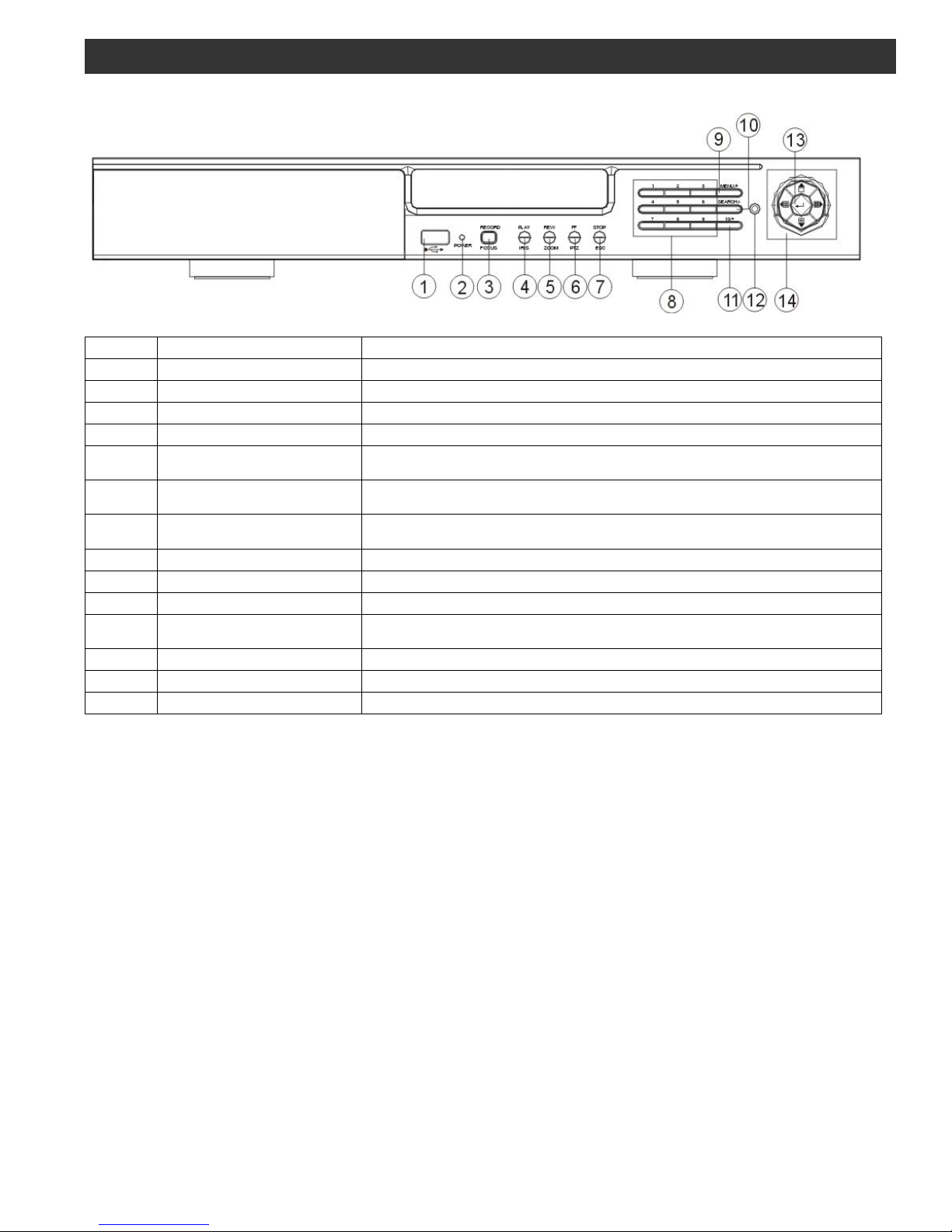
1. Front Panel – 4 / 8 CH.
Item #
Label Name
Function
1 USB Connect USB thumb drive or mouse
2
POWER
Power indicator
3
REC / FOCUS
Manual record / FOCUS adjustment(PTZ)
4
Play / IRIS
Enter Playback/ IRIS adjustment (PTZ)
5 REW / ZOOM
REW on playback mode /
ZOOM adjustment (PTZ)
6 FF / P.T.Z.
FF on playback mode /
Enter PTZ mode
7 STOP / ESC
STOP playback on playback mode /
Exit MENU or jump back to previous page
8 Digital Enter digital or select channel
9 MENU / + Enter MENU page / increase value
10
SEARCH / -
Enter SEARCH page / dec r eas e val ue
11 10+
To enter digital over 10 /
Continuously press twice to have 10
12 IR receiver Remote receiver
13 Enter Enter
14 Split / Direction Key Switch split / Move selected item
PANEL DEFINITION
HDRR-04 / HDRR-08 / HDRR-16 Quick Setup Guide
- 3 - DV-18 / DV-19 / DV-20
R201404-V23
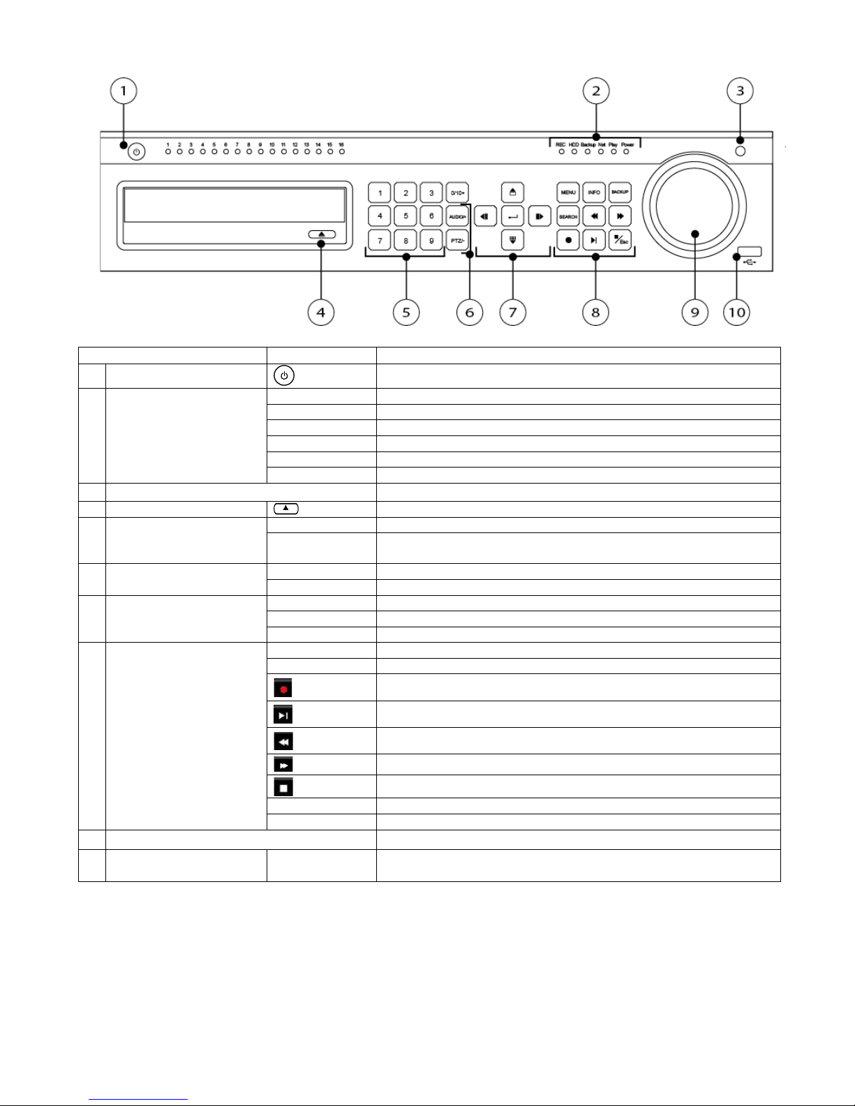
2. Front Panel – 16 CH.
Item #
Label Name
Function
1
Power Switch
Power on/off
2
Work state indicator
REC
When recording, the light is blue
HDD
When HDD is writing and reading , the light is blue
Backup
When backup files and data, the light is blue
Net
When access to network , the light is blue
Play
When playing video, the light is blue
Power
Power indicator, when connection , the light is blue
3
IR receiver
Remote receiver
4
Eject Button
Eject DVD
5
Digital Button
1-9
Input number 1-9 or choose camera
0/10+
Input number0, 10 and the above number together with other
digital keys
6
Compound Button
P.T.Z./-
1. Enter PTZ mode in live 2. Decrease the value in setup
AUDIO/+
1. Control voice 2. Increase the value in setup
7
Input button
Direction button
Change direction to select items
Multi-screen
Change screen display mode like1/4/9/16 channel
Enter button
Confirm selection
8
Function button
MENU
Enter menu in live
INFO
Check recording data
Record manually
Play/Pause
Rewind
Fast forward
Exit
BACKUP
Enter backup mode in live
SEARCH
Enter search mode
9
Split / Direction Key Switch split / Move selected item
10
USB USB port
To connect external USB devices like USB flash, USB HDD for
backup or update firmware;

HDRR-04 / HDRR-08 / HDRR-16 Quick Setup Guide
- 4 - DV-18 / DV-19 / DV-20
R201404-V23
3. Back Panel – 4 CH.
Item #
Label Name
Function
1 ALARM OUT Alarm outputs; connect to external alarm
2 ALARM IN Alarm inputs for connecting sensors
3
P/Z
Connect to speed dome
4
K/B
Connect to keyboard
5
CVBS
CVBS output
6
AUDIO OUT
Audio out, connect to sound box
7
MIC IN
Talk, connect to microphone
8
AUDIO IN
Audio inputs
9 HD SDI Video IN HD SDI video inputs
10 HDMI port Connect to high-definition display device
11 VGA port VGA output, connect to monitor
12 LAN port Network
13 USB port Connect external USB devices like USB flash drive, HDD
14
Power Supply
12V DC
4. Back Panel – 8 CH.
Item #
Label Name
Function
1
Alarm Out
1-ch relay output. Connect to external alarm.
2
GND
Grounding for Alarm In
3
Y/Z
Connect to speed dome, Y is TX+; Z is TX-
4
A/B
Connect to keyboard; A is TX +; B is TX-
5 CVBS Port CVBS video sign al out put
6 Audio Out Audio output, connect to the sound box
7 Audio In 4-ch audio inputs
8 Alarm In Connect to external sensor1-8
9 HDSDI Video In 8-ch SDI video inputs
10
HDMI Port
Connect to high-def inition display device
11
VGA port
VGA output, connect to monitor
12
LAN
Network port
13 USB Port
To c onnect external USB devices like USB f lash, USB HDD for backup or
update firmware; or connect to USB mouse
14
Power Supply 12V DC
 Loading...