

Okina USA DHR-08, DHR-16 Quick Setup Manual
MADE IN TAIWAN DV-13 / DV-14 / DV-15
Copyright © 2014 OKINA USA. All rights reserved. R201406-V03
Please read this Quick Setup Guide before installation.
*Notes: Any Return Must Include All Components.
Additional charges apply for any missing components. A UPS Battery Backup System is
highly recommended to avoid power failure restoration damage to Hard Drive & Motherboard.
**Quick Setup Guide & User’s Manual are subject to change without notice.
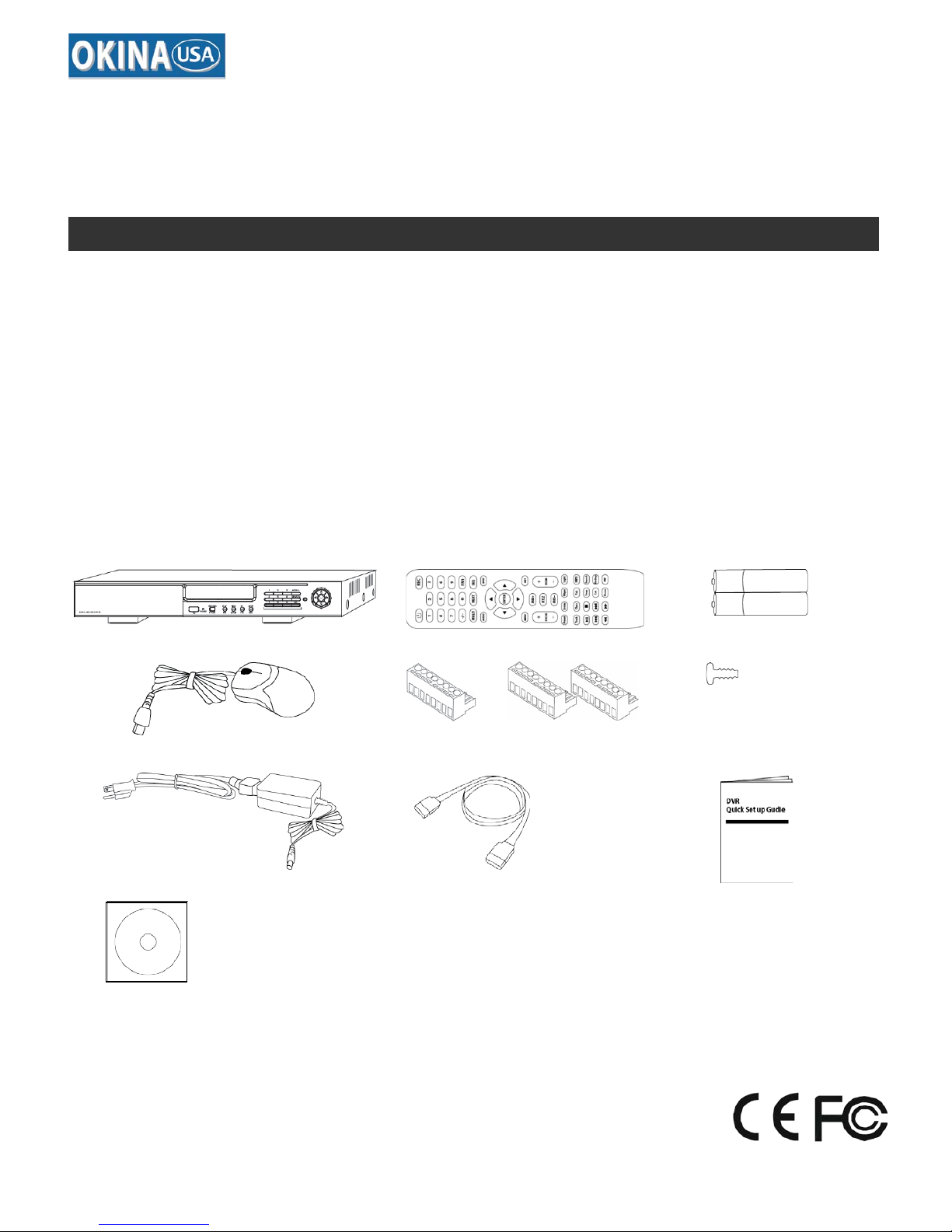
A.
One (1)
DHR-08 / DHR-16 DVR
B.
One (1)
Remote Controller
C.
Two (2)
AAA Battery for Remote Controller
D.
One (1)
USB Mouse
E.
One (1)
8 Screw on Terminal Connector - DHR-08
Two (2)
8 Screw on Terminal Connector - DHR-16
F.
Eight (8)
Hard Drive Screws
G.
One (1)
12V DC / 5Amp Power Supply with Power Cord
H.
Two (2)
SA TA Cable Inside
I.
One (1)
Quick Set up Guide Book
J.
One (1)
User’s Manual & CMS Software CD
A.
B.
C.
D.
E.
F.
G.
H.
Inside the DVR
I.
J.
DHR-08
DHR-16
960H Realtime DVR – 8 / 16 CH.
Quick Setup Guide
PACKAGE CONTENTS
x 8
x 2
x 2 (16 CH.)
x 2
x 1 (8 CH.)
DHR-08 / DHR-16 Quick Setup Guide
DV-16 / DV-17
R201404-V21
- 2 -
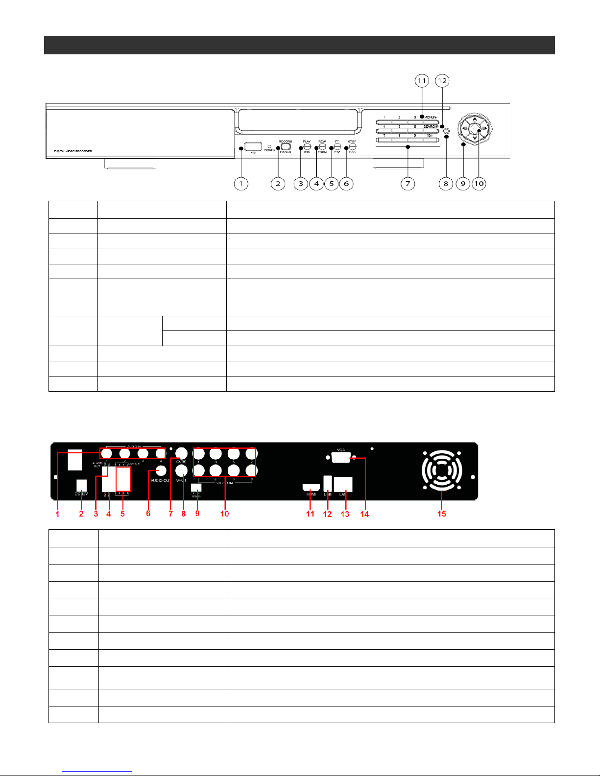
1. Front Panel
Item # Label Name Function
1 USB Connect USB thumb drive or mouse
2 REC / FOCUS Manual record / focus adjustment(PTZ)
3 PLAY / IRIS Enter Playback/ iris adjustment (PTZ)
4 REW / SPEED Fast rewind on playback mode / speed adjustment (PTZ)
5 FF / P.T.Z. Fast forward on playback mode / enter PTZ mode
6 STOP / ESC
Stop playback on playback mode /
Exit menu or jump back to previous page
7 Digital Button
1 - 9
Input number 1-9 or choose camera
10/+
Input number 10 and the above number together with other digital
8 IR receiver Remote receiver
9 Split / Direction Key Switch split / Move selected item
10 Enter Validate action
2. Back Panel – 8 CH.
Item # Label Name Function
1 Audio in 4-ch audio inputs
2 DC 12V Power input
3 Alarm out 1-ch relay output. Connect to external alarm.
4 GND Grounding for Alarm in
5 Alarm in Connect to external sensor1-8
6 Audio out Audio output, connect to the sound box
7 CVBS port CVBS video signal out put
8 Spot
Connect to monitor as an AUX output channel b y channel. Video would be
displayed without OSD.
9 RS485 Connect to keyboard or speed dome
10 Video in Video input channels from 1-8
PANEL DEFINITION
DHR-08 / DHR-16 Quick Setup Guide
DV-16 / DV-17
R201404-V21
- 3 -
Item # Label Name Function
11 HDMI port Connect to high-definition display device
12 USB port
To connect external USB devices like USB flash, USB HDD for backup or
update firmware; or connect to USB mouse
13 LAN Network port
14 VGA port VGA output, connect to monitor
15 Fan For cooling the device
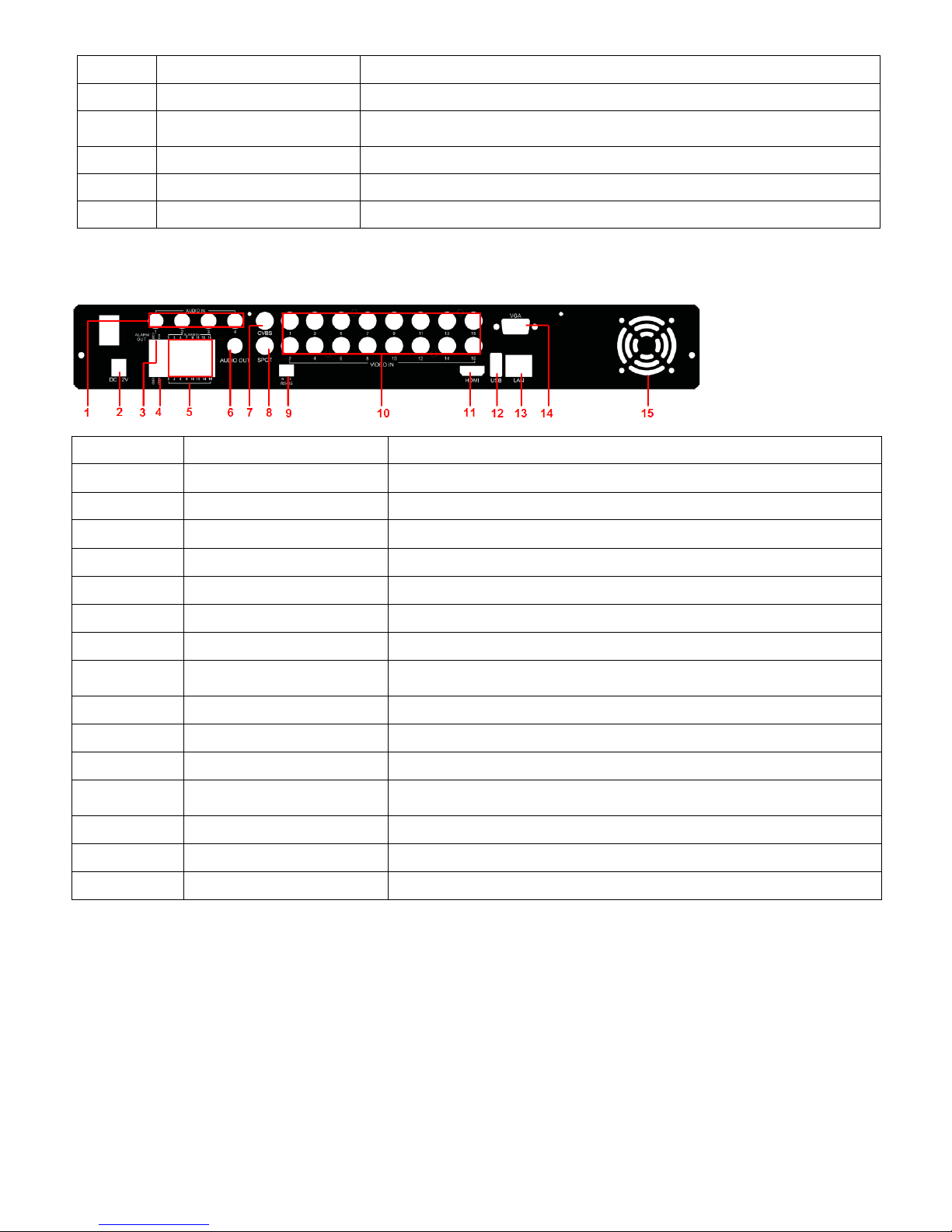
3. Back Panel – 16 CH.
Item # Label Name Function
1 Audio in 4-ch audio inputs
2 DC 12V Power input
3 Alarm out 1-ch relay output. Connect to external alarm.
4 GND Grounding for Alarm in
5 Alarm in Connect to external sensor1-16
6 Audio out Audio output, connect to the sound box
7 CVBS port CVBS video s ign al out put
8 Spot
Connect to monitor as an AUX output channel by channel. Video would be
displayed without OSD.
9 RS485 Connect to keyboard or speed dome
10 Video in Video input channels from 1-16
11 HDMI port Connect to high-definition d isplay device
12 USB port
To connect external US B d evices lik e USB f lash, USB HDD f or bac k up or
update firmware; or connect to USB mouse
13 LAN Network port
14 VGA port VGA output, connect to monitor
15 Fan For cooling the device
 Loading...