

Okina TVI-04, TVI-08, TVI-16-1U, TVI-16 User Manual
Thank you for purchasing our product.
Please read this user’s manual before using the product.
Change without notice
Type A: 1 SATA (TVI-04 / TVI-08 / TVI-16)
Type B: 2 SATA (TVI-16-1U)
H.264 4/8/16 CH
Analogue HD
TVI-DVR
User’s Manual

TVD-04 / TVD-08 / TVD-16 / TVD -16-1U User’s Manual
2
CAUTION
Please read this user manual carefully to ensure that you can use the device correctly and safely.
There may be several te chn ically inc orr e ct p lac es or pr i ntin g er ror s in t his ma nua l. T he u pdates will be added into the
new version of this manual. T he contents of this manual are subject to change without notice.
This device should be operated only from the type of power source indicated on the marking label. The voltage of the
power must be verified before using. If the device doesn’t work for a long time, pull out the plug from the socket.
Do not install this device near any heat so urce s su ch as ra di ator s, h eat reg ist er s, stov es or other dev ic e that produce
heat.
Do not install this device near water. Clean only with a dry cloth.
Place the device in a well-ventilated area.
Do not power off the DVR at normal recording condition! The correct operation to shut off DVR is to stop recording
firstly, and then to select “shut-down” button at the right of the menu bar to exit, and finally to cut off the power.
This machine is indoor using equipment. Do not expose the machine in rain or moist environment. In case any solid
or liquid get into the machi ne’s case, please cut off the p ower supply immediately, and ask for qual ifie d t ec hni cia ns t o
check the machine before restart
Do not try to repair the device by yourself without technical aid or approval.
When this product is i n u se, th e r el ev ant co ntents of Microsoft, Apple and Google will be involved in. The pictures and
screenshots in this manual are only used to explain the usage of our product. The ownerships of trademarks, logos
and other intellectual properties related to Microsoft, Apple and Google shall belong to the above-mentioned
companies.
This manual is suitable for 4/8/16 channel digital video recorders.

TVD-04 / TVD-08 / TVD-16 / TVD -16-1U User’s Manual
3
1.1 Main Fea t ures
COMPRESSION FORMAT
• Standard H.264 compression with low bit rate and better image quality
LIVE SURVEILLANCE
• Supports HDMI/ VGA output
• Supports channel security by hiding live display
• Display the local record state and basic information
• Supports USB to make full control
RECORD MEDIA
• Type A supports one SATA HDD / Type B two SATAs to record for a longer time without any limitation
BACKUP
• Supports USB 2.0 devices to backup
• Supports external SATA DVD writer to backup
• Supports saving recorded files with AVI standard format to a remote computer through internet
RECORD & PLAYBACK
• Record modes: Manual, Schedule, Motion detection recording
• Supports recycle after HDD full
• Resolution, frame rate and picture quality are adjustable
• 4/8/16 CH 720P / 1080P / 960H and IP recording
(IP function: 4CH model supports 1 IP cam、8CH model supports 4 IP cam、16CH model supports 8 IP cam)
• 1 audio channel available
• Three record search modes: time search, event search and image search
• 4/8/16 channels playback simultaneously
• Supports deleting and locking the recorded files one by one
• Supports remote playback in Network Client through LAN or internet
ALARM
• Supports schedule for motion detection
• Supports pre-recording and post recording
PTZ CONTROL
• Supports various PTZ protocols
• Supports 128 PTZ presets and 8 auto cruise tracks
• Supports remote PTZ control through internet
SECURITY
• Customize user right: log search, system setup, two way audio, file management, disk management, remote
login, live view, manual record, playback, PTZ control and remote live view
• Supports 1 administrator and 63 users.
• Supports event log recording and checking, events unlimited
NETWORK
• Supports TCP/IP, DHCP, PPPoE, DDNS protocol
• Supports IE browser to do remote view
• Supports setup client connection amount
• Supports dual stream. Network stream is adjustable independently to fit the network bandwidth and
environment.
• Supports picture snap and color adjustment in remote live
• Supports remote time and event search, and channel playback with picture snap
• Supports remote PTZ control with preset and auto cruise
• Supports remote full menu setup, changing all the DVR parameters remotely
• Supports mobile surveillance by phones with iPhone, Android
• Supports NVMS to manage multi devices on internet
※
960H resolution recording capabilities, will be based on purchase models.
TVD-04 / TVD-08 / TVD-16 / TVD -16-1U User’s Manual
4
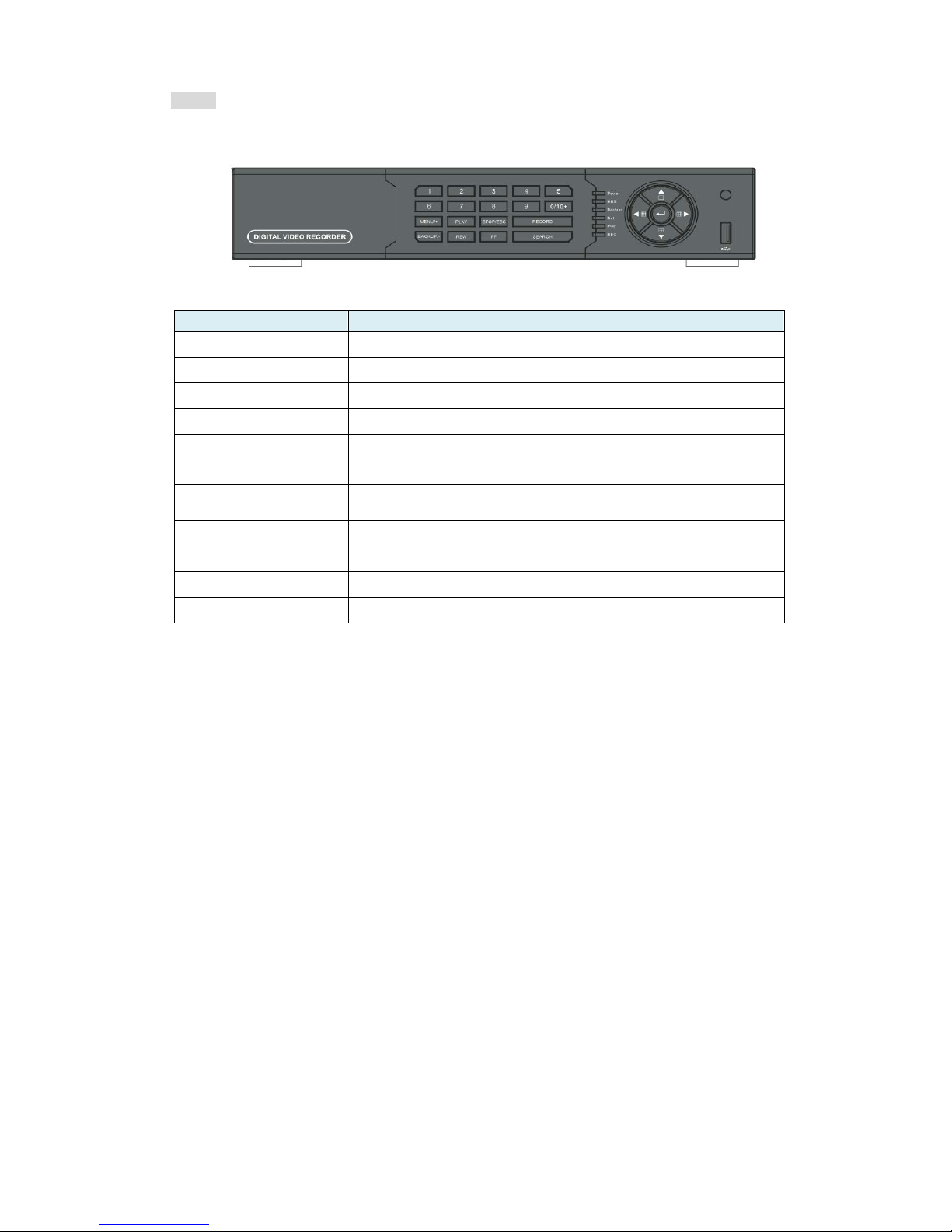
1.2 Front Panel Instructions
• Notice: The pictures are only for reference; please make the object as the standard.
Front Panel (Type A): TVD-04 / TVD-08 / TVD-16
Front Panel (4/8/16CH)
Label Name
Function
REC / FOCUS Manual record / focus adjustment(PTZ)
PLAY / IRIS Enter Playback/ iris adjustment (PTZ)
REW / SPEED
Fast rewind on playback mode /speed adjustment (PTZ)
FF / P.T.Z.
Fast forward on playback mode /enter PTZ mode
MENU / +
Enter menu page / increase value
BACKUP / -
Enter backup page / decrease value
STOP / ESC
Stop playback on playback mode /
Exit menu or jump back to previous page
Split / Direction Key
Switch split / Move selected item
Enter
Validate action
USB Connect USB thumb drive or mouse
IR receiver
Remote receiver
TVD-04 / TVD-08 / TVD-16 / TVD -16-1U User’s Manual
5
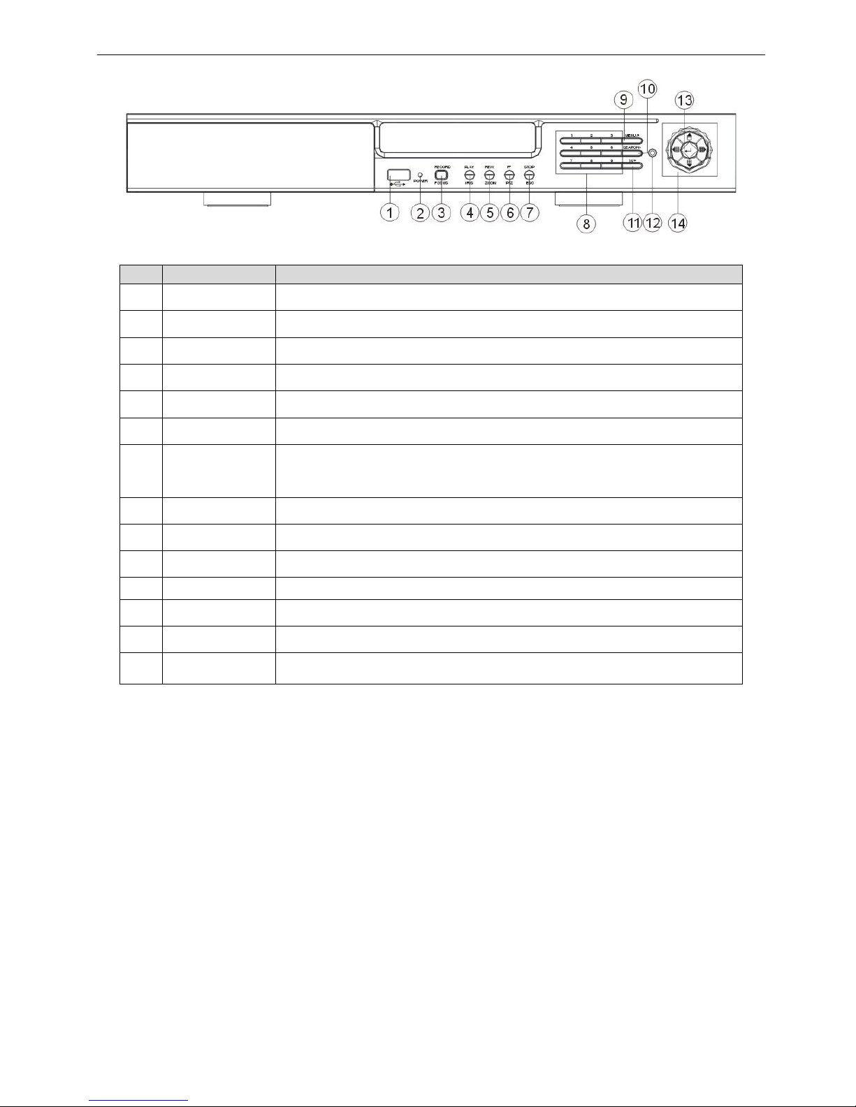
Front Panel (Type B): TVD-16-1U
16CH
No
Label Name
Function
1 USB Connect USB thumb drive or mouse
2 POWER Power indicator
3 REC / FOCUS Manual record / FOCUS adjustment(PTZ)
4 PLAY / IRIS Enter Playback/ IRIS adjustment (PTZ)
5
REW / ZOOM
REW on playback mode / ZOOM adjustment (PTZ)
6
FF / P.T.Z.
FF on playback mode /Enter PTZ mode
7
STOP / ESC
STOP playback on playback mode / Exit MENU or jump back to previous page
8
Digital
Enter digital or select channel
9
MENU / +
Enter MENU page / increase value
10
SEARCH / -
Enter SEARCH page / dec r eas e val ue
11
10+
To enter digital over 10 / Continuously press twice to have 10
12
IR receiver
Remote receiver
13
Enter
Enter
14
Split / Direction
Key
Switch split / Move selected item
TVD-04 / TVD-08 / TVD-16 / TVD -16-1U User’s Manual
6
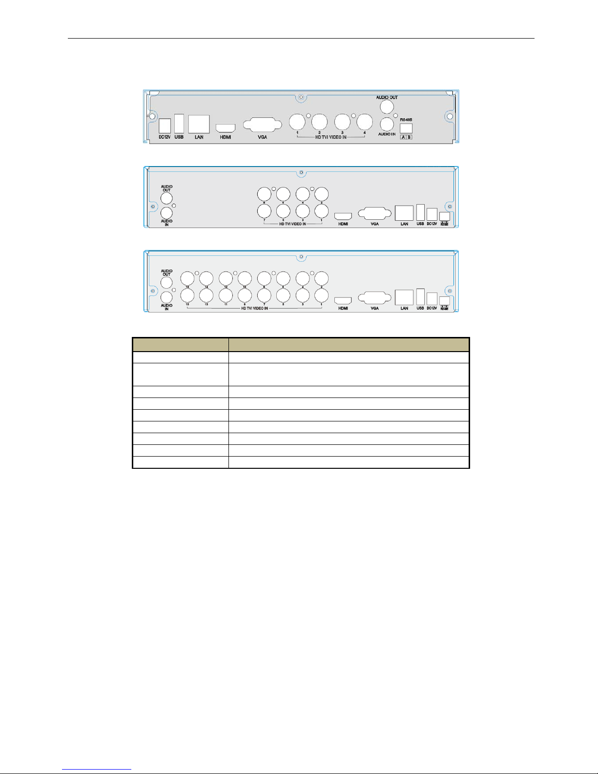
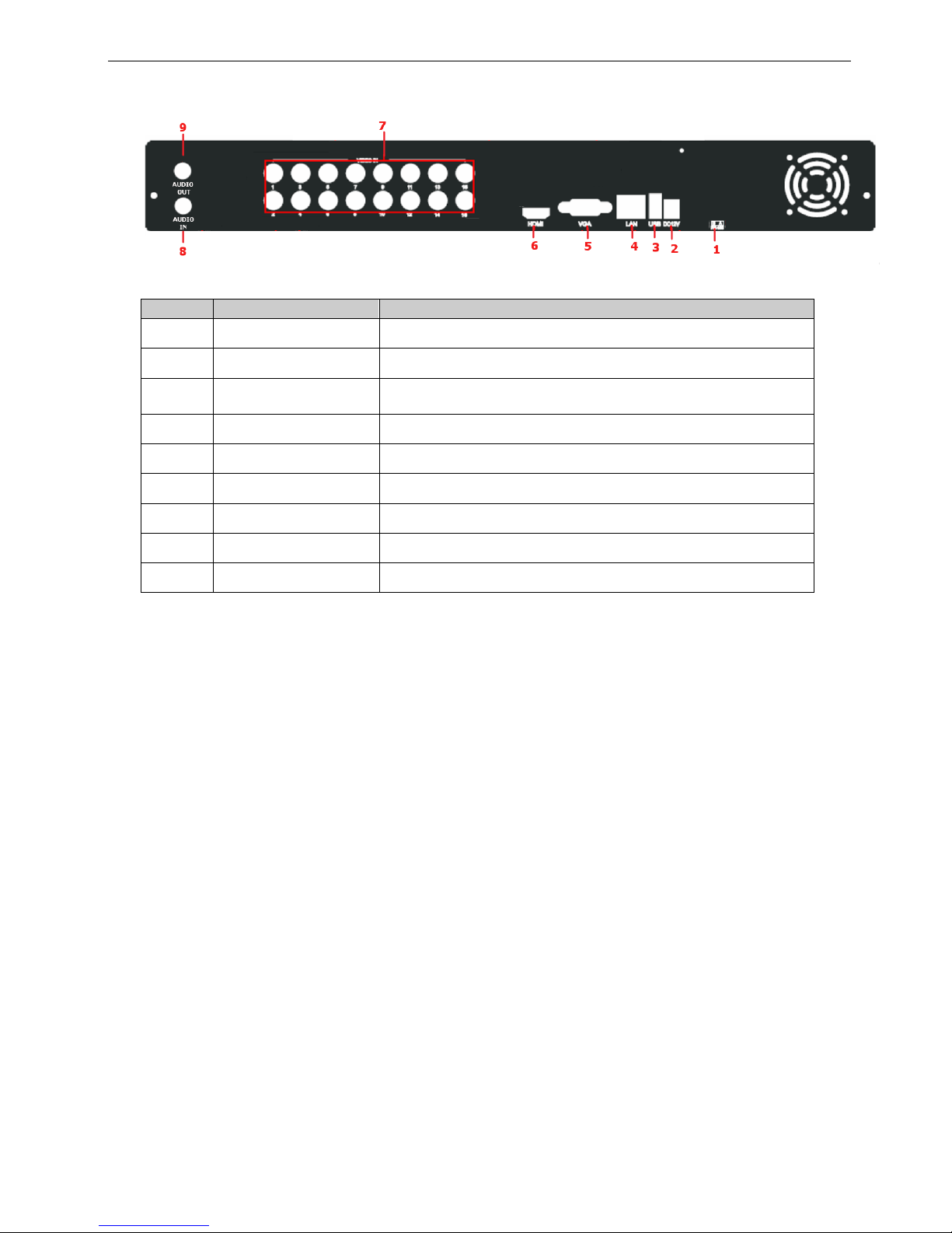
1.3 Rear Panel Instructions
T y pe A : TVD-04 / TVD-08 / TVD-16
Rear Panel for 4 CH
Rear Panel for 8 CH
Rear Panel for 16 CH
Name
Descriptions
DC12V
DC12V Power Input.
USB
To connect external USB devices like USB mouse or
USB storage device.
LAN
Network Port.
HDMI
HDMI Port. Connect to high-definition display device.
VGA
VGA Port. Connect to monitor.
HD TVI VIDEO IN
4/8/16 CH HD TVI Video Inputs.
AUDIO OUT
Audio output, connect to the sound box.
AUDIO IN
1 CH Audio Input.
RS485
Connect to keyboard or speed dome; A is TX +; B is TX-.
TVD-04 / TVD-08 / TVD-16 / TVD -16-1U User’s Manual
7
Type B: TVD-16-1U
Rear Panel for 16-ch
Item
Label name
Function
1 RS485 Connect to speed dome or keyboard
2 POWER INPUT DC12V
3 USB
To connect external USB devices like U SB flash, USB HDD f or
backup or update firmware; or connect to USB mouse
4 LAN Network port
5 VGA VGA output, connect to monitor
6 HDMI Connect to high-defin iti on d isplay device
7 VIDEO IN TVI Video input channels from 1-16
8 AUDIO OUT Audio output, connect to the sound box
9 AUDIO IN 1 CH Audio input
TVD-04 / TVD-08 / TVD-16 / TVD -16-1U User’s Manual
8
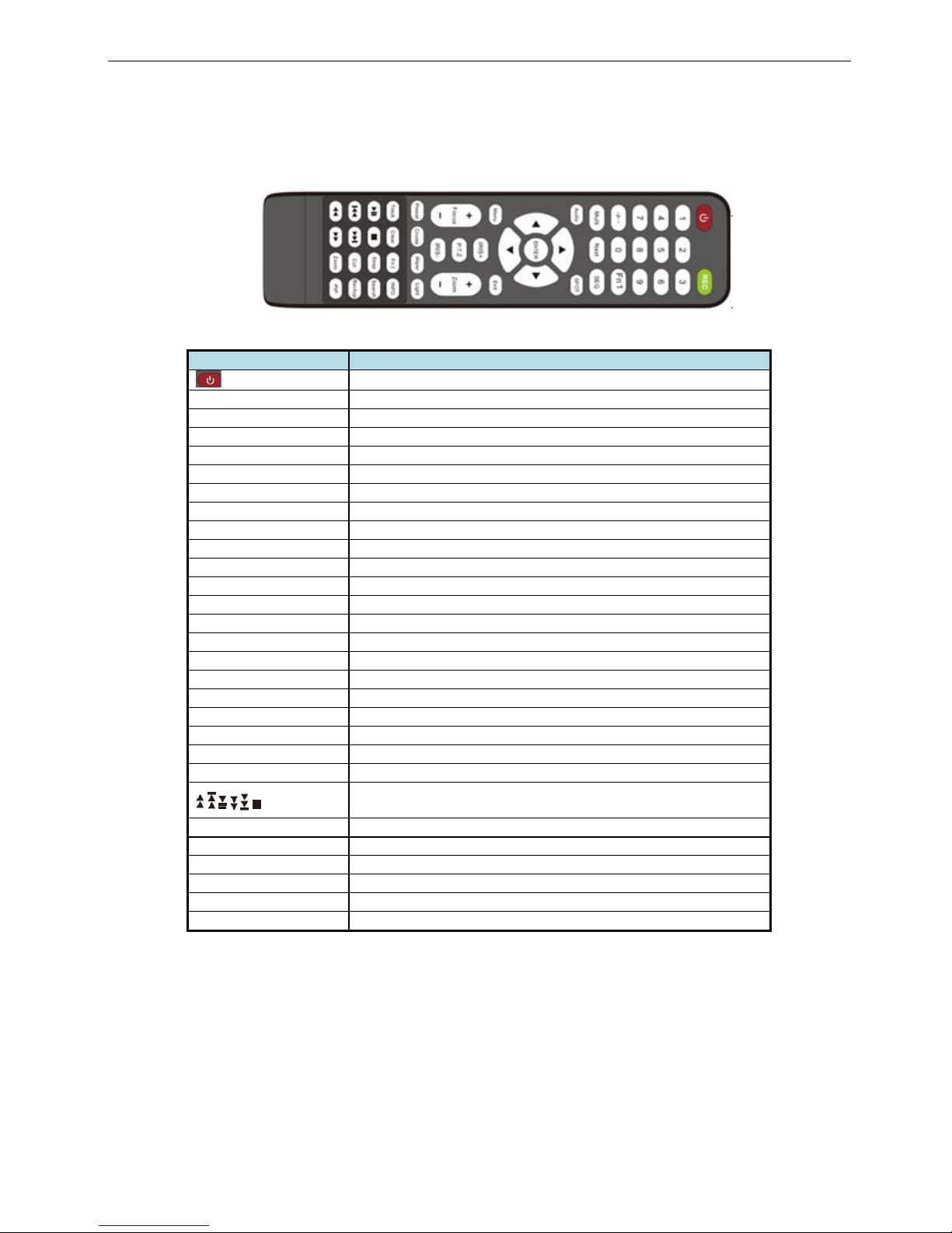
1.4 Remote Controller (Optional)
It uses two AAA size batteries.
• Open the battery cover of the Remote Controller.
• Place batteries. Please take care of the polarity (+ and -).
• Replace the battery cover.
Fig. 1-4 Remote Controller
Button
Function
Power Button
Switch off—to stop DVR. Use it before turning off the power
Record Button
To record manually
-/-- /0-9 Digital Button
Input number or choose camera
Fn1 Button
Unavailable temporarily
Multi Button
To choose multi screen display mode
Next Button
To switch the live image
SEQ
To enter into auto dwell mode
Audio
To enable audio output in live mode
Switch
To switch the output between BNC and VGA
Direction button
To move cursor in setup or pan/title PTZ
Enter Button
To confirm the choice or setup
Menu Button
To enter into menu
Exit Button
To exit the current interface
Focus/IRIS/Zoom/PTZ
To control PTZ camera. Move camera/zoom/IRIS/Focus
Preset Button
To enter into preset setting in PTZ mode
Cruise Button
To enter into cruise setting in PTZ mode
Track Button
To enter into track setting in PTZ mode
Wiper Button
To enable wiper function in PTZ mode
Light Button
To enable light function in PTZ mode
Clear Button
To return to the previous interface
Fn2 Button
Unavailable temporarily
Info Button
Get information about DVR like firmware version, HDD information
To control playback. Play/Pause/Stop/Previous Section/Next
Section/Rewind/Fast Forward
Snap Button
To take snapshots manually
Search Button
To enter into search mode
Cut Button
To set the start/end time for backup in playback mode
Backup Button
To enter into backup mode
Zoom Button
To zoom in the images
PIP Button
To enter into picture in picture setting mode
TVD-04 / TVD-08 / TVD-16 / TVD -16-1U User’s Manual
9
1.5 Control with Mouse
1.5.1 Connect Mouse
It supports USB mouse through the port on the rear panel, please refer to Fig.1-4Remote Controller.
Notice: If mouse is not detected or doesn't work, check below steps:
1. Make sure the mouse is connected to the USB mouse port not the USB port
2. try another mouse
1.5.2 System operation by mouse
The structure of the main menu is shown in Fig.1-4 Remote Controller.
In live:
Double-click left button on one camera to be full screen disp lay. Double-click again to return to the previous
screen display.
Click right button to show the control bar at the bottom of the screen as Fig.1-4 Remote Controller. Here are all
control and setup. Click right mouse again to hide the control bar.
In setup:
Click left button to enter. Click right button to cancel setup, or return to the previous.
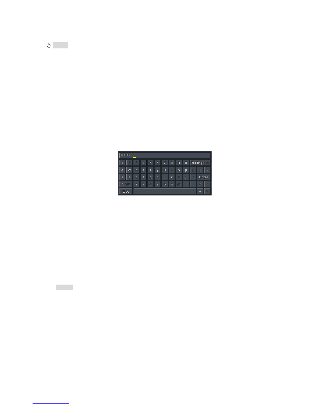
If want to input the value, move cursor to the blank and click. An input window will appear as Fig.1-5. It
supports digitals, letters and symbols input.
Fig. 1-5 Digital Numbers and Lette rs Input Window
Users can change some v alue by the wheel, such as tim e. Move cursor onto the value, and roll t he wheel
when the value blinks.
It supports mouse drag. I.e. Set motion detection area: click customized, hold left button and drag to set motion
detection area. Set schedule: hold left button and drag to set schedule time
In playback:
Click left button to choose the options. Click right button to return to live mode.
In backup:
Click left button to choose the options. Click right button to return to previous picture.
In PTZ control:
Click left button to choose the buttons to control the PTZ. Click right button to return to live.
• Notice: Mouse is the default tool in all the operation below unless Exceptional indic ation.

TVD-04 / TVD-08 / TVD-16 / TVD -16-1U User’s Manual
10
2 Basic Function Instruction
2.1 Power On/Off
Before you power on the unit, please make sure all the connection is good.
2.1.1 Power on
Step1: connect with the source power; switch on the power button near the power port in the rear panel
Step2: the device will start to boot, and the power in dic ator will become blue
Step3: before start, a WIZARD dialogue box will pop-out (refer to below picture) and show some information
about time zone and time setup, IP information, record quick setup and HDD information page.
After the device powers on , if there is no menu or onl y has live image display, user can long press ES C
button to switch.
• Notice: this s erial device can only display menu on VGA monitor or BNC monitor at one time, if there is
live image display without menu display, please check up whether other device has menu display firstly, or
long press ESC key to wait for login dialog box to appear.
2.1.2 Power off
User can power off the device by using remote controller, keyboard and mouse.
By remote controller:
Step1: press Power button, the shut down window will appear, click OK, the unit will power off after a while.
Step2: disconnect the power
By keyboard and mouse:
Step1: enter into Menu, then select “System Shut Down” icon, the Shut down window will appear
Step2: click OK, the unit will power off after a while.
Step3: disconnect the power
2.2 Login
User can login and logout the DVR system. User cannot do any other operations except changing the
multi-screen displa y once logou t.
Fig. 2-1 Login
• Notice: the default user name and password is “admin” and 123456”
• The concrete operation steps for change password, add or delete user please refer to Fig 2-1 User
management configuration for more details.
TVD-04 / TVD-08 / TVD-16 / TVD -16-1U User’s Manual
11
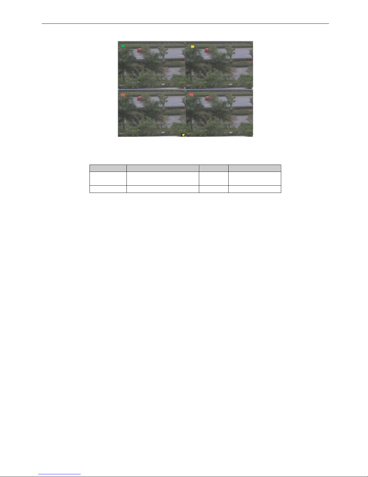
2.3 Live preview
2.3.1
Fig. 2-2 live preview interface
The explanation of symbol in the live preview interface:
symbol
meaning
symbol
meaning
Green Manual record Red
Alarm in trigger
record
Yellow
Motion detection record
Blue
Schedule record
TVD-04 / TVD-08 / TVD-16 / TVD -16-1U User’s Manual
12
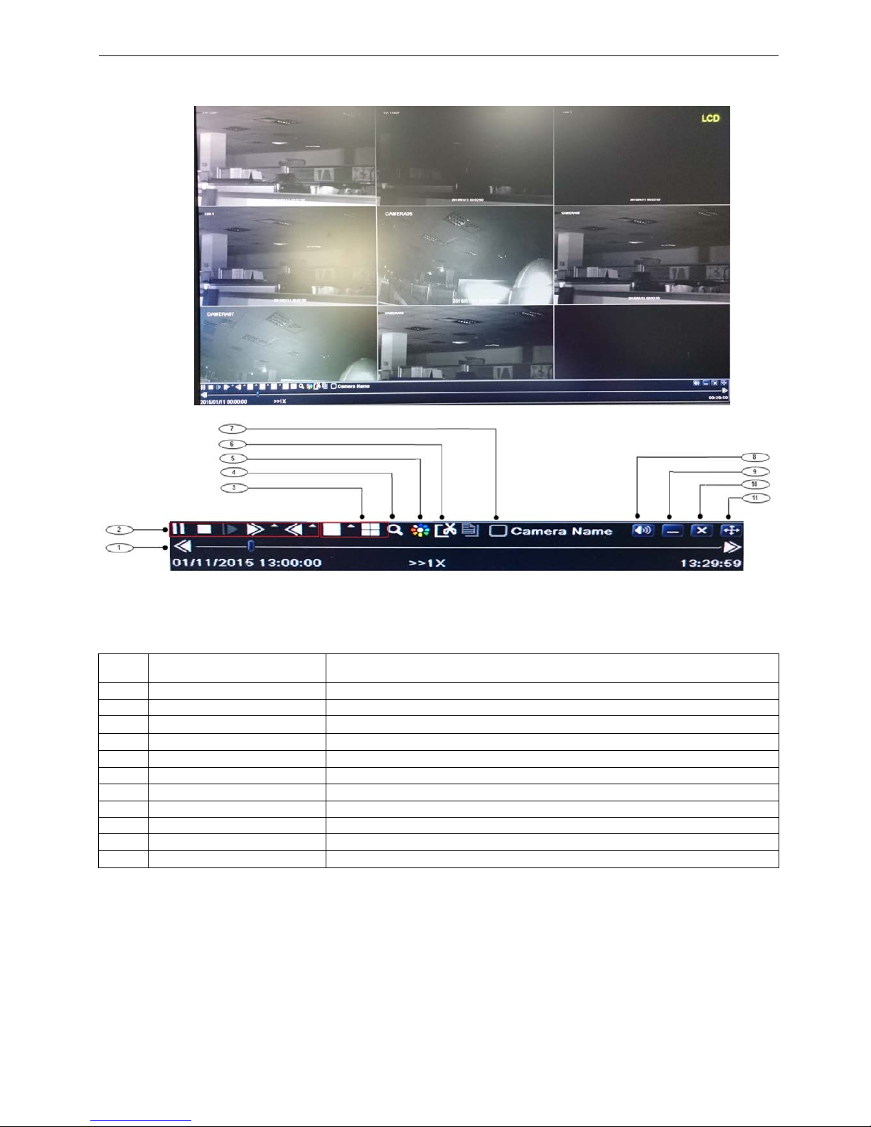
2.3.2 Live playback
Click Play butt on to playback the recorde d video. Refer to Figure2-3. Us er can do concrete operat ion by
click the buttons on screen.
Fig. 2-3 live playback
Item Function Description
1
Playback process bar
Last/next segment of record and time process
2
Playback basic function
Play/ Pause / Stop / frame forward / fast forward / fast rewind
3
Display mode
4ch:1/ 4, 8ch、16ch:1/ 4/ 6/ 9/ 1+5/ 1+7,
4
Zoom
Screen digital zoom x2
5
Color
Setup picture color
6
Cut
Enable to select a specific part of the video and back it up on usb drive
7
Camera name
Enable or disable camera name display
8
Volume
Volume mute on/off
9
Reduce
Hide playback tool bar
10
Exit playback mode
11 Move the playback bar in the screen
TVD-04 / TVD-08 / TVD-16 / TVD -16-1U User’s Manual
13
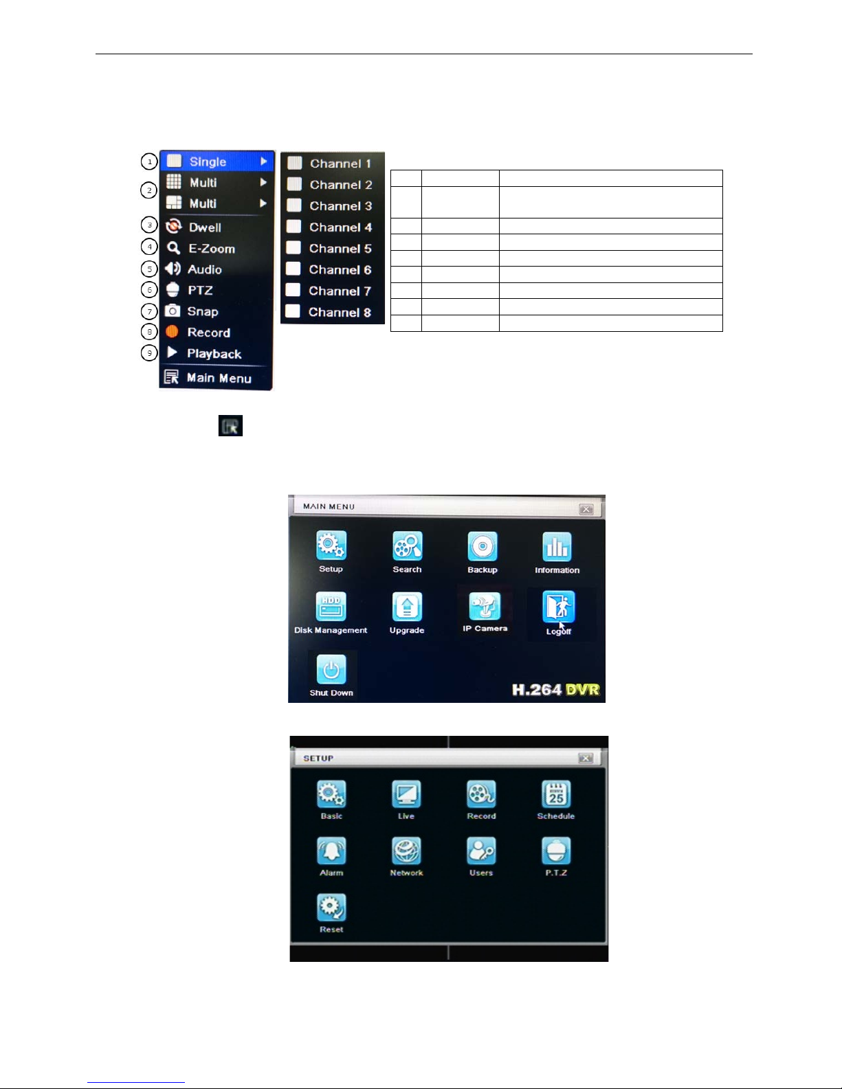
3 Main menu setup guide
Click right mous e or pr es s ESC b ut to n on th e f r ont panel, t he control bar will display on the screen, ref er to
Fig 3-1:
1
Single
Full channel
2
Multi
4ch:1/5, 8ch:1/4/9/12,
16ch:1/4/9/16/25
3
E-Zoom
Live/playback digital zoomx2
4
Audio
Audio channel setup and volume
5
PTZ
Into PTZ control mode
6
Record
Manual record
7
Playback
Playback the nearest file
8
Main Menu
Into main OSD
9
Dwell
Channel sequence
Fig. 3-1 main menu toolbar
Click Menu button, the interface will pop-up as Fig. 3-2; press MEN U button on the front panel or
operate with remote controller also can display the main menu.
Main OSD
Fig. 3-2 system setup
Full channel switch, camera 1 ~ 5, camera 1 ~ 12, or camera 1~24
TVD-04 / TVD-08 / TVD-16 / TVD -16-1U User’s Manual
14
3.1 Basic configuration
Basic configuration includes three sub menus: system、date& time and DST.
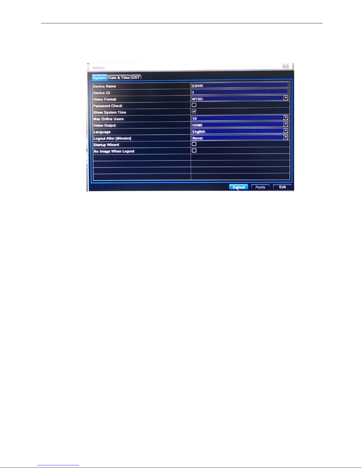
3.1.1 System
Step1: enter into system configurationbasic configurationsystem; refer to Fig 3-3:
Fig 3-3 basic configuration-basic
Step2: in this interface user can setup the d evice name, de vice ID, video f ormat, max networ k users, VGA
resolution and language. The definitions for every parameters display as below:
Device name: the nam e of the devic e. It m a y displa y on t he c lient en d or CMS that help user t o rec ogni ze
the device remotely.
Video format: two modes: PAL and NTSC. User can select the video format according to that of camera.
Password check: enab le this option, user needs to input us er name and passw ord can do corres ponding
operations with the relevant right in system configuration.
Show time: display time in live.
Max network uses: set the max user amount of network connection
Video Output: the resolution of live display interface, range from: VGA800*600、 VGA1024*768、
VGA1280*1024, and HDMI
Language: setup the menu language.
Logout after [Minutes]: defines time to logout the user from the OSD
Startup wizard: tick off this item, there will display an opening wizard with time zone and time setup
information
No Image when Logout: if this option is tick, when user logout, live picture will be hidden
Note: after changed the language and video output, the device needs to logi n again.
TVD-04 / TVD-08 / TVD-16 / TVD -16-1U User’s Manual
15
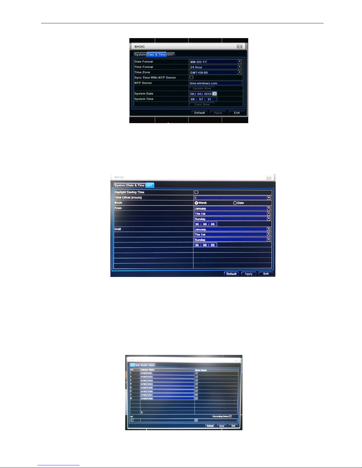
3.1.2 Time & date
Step1: enter into system configurationbasic configurationtime & date; refer to Fig 3-4:
Fig. 3-4 basic configuration-time & date
Step2: set the date format, time format, time zone in this interface; click off “sync time with NTP server” to refresh NTP server date; user
also can adjust system date manually
Step3: click “default” button to resort default setting; click “apply” button to save the setting; click “exit” button to exit current interface.
3.1.3 DST
Step1: enter into system configurationbasic configurationDST; refer to Fig. 3-5:
Fig. 3-5 basic configuration-DST
Step2: in this interface, enable daylight saving time, time offset, mode, start & end month/week/date, etc.
Step3: click “default” button to resort default setting; click “apply” button to save the setting; click “exit” button
to exit current interface.
3.2 Live configuration
Live configuration includes four submenus: live, main monitor and mask.
3.2.1 Live
In this interface, user can setup camera name.
Step1: enter into system configurationlive configurationlive; refer to Fig 3-6:
Fig. 3-6 live configurationlive
TVD-04 / TVD-08 / TVD-16 / TVD -16-1U User’s Manual
16
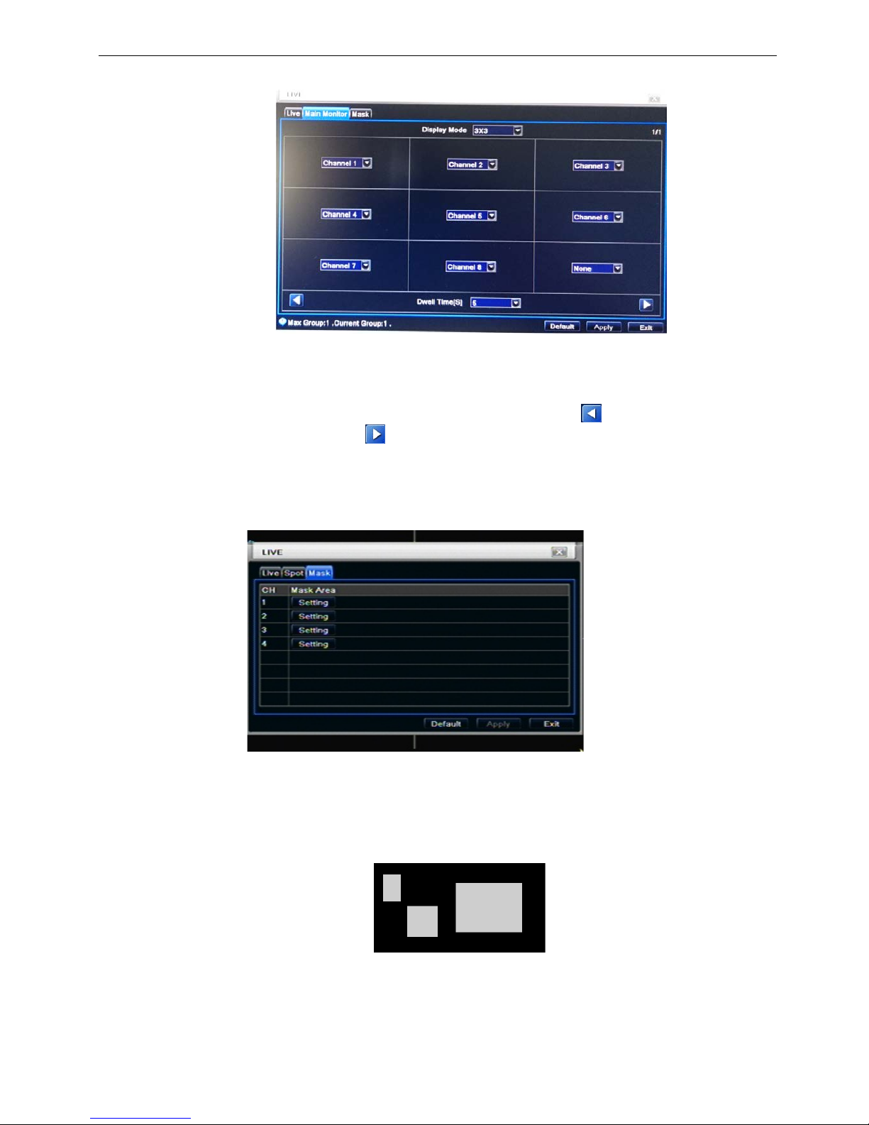
3.2.2 Main monitor
Step1: enter into system configurationlive configurationmain monitor; refer to Fig 3-8:
Fig. 3-8 live configuration-main monitor
Step2: select split mode: 1×1、2×2、2×3、3×3、4×4 and channel
Step3: dwell time: the time interval for a certain dwell picture display switching to next dwell picture display
Step4: selected the split mode, then setup current picture group. Click
button to setup the previous
channel groups of dwell picture, click
button to set the latter channel groups of dwell picture.
Step5: click “default” button to resort default setting; click “apply” button to save the setting; click “exit” button
to exit current interface.
3.2.3 Mask
User can setup private mask area on the live image picture, max threes areas
Fig. 3-9 live configuration-mask
Setup mask area: click Setting butt on, enter into liv e im age to pres s left mouse and dr ag m ouse to set mask
area, refer to below picture. Click Apply button to save the setting.
Delete mask area: select a c er tain m ask ar ea, clic k left mouse to delete that mask area, click Apply button to
save the setting.
Setup mask area
Notice: The mask area will not be recorded on DVR. Please use this function carefully.
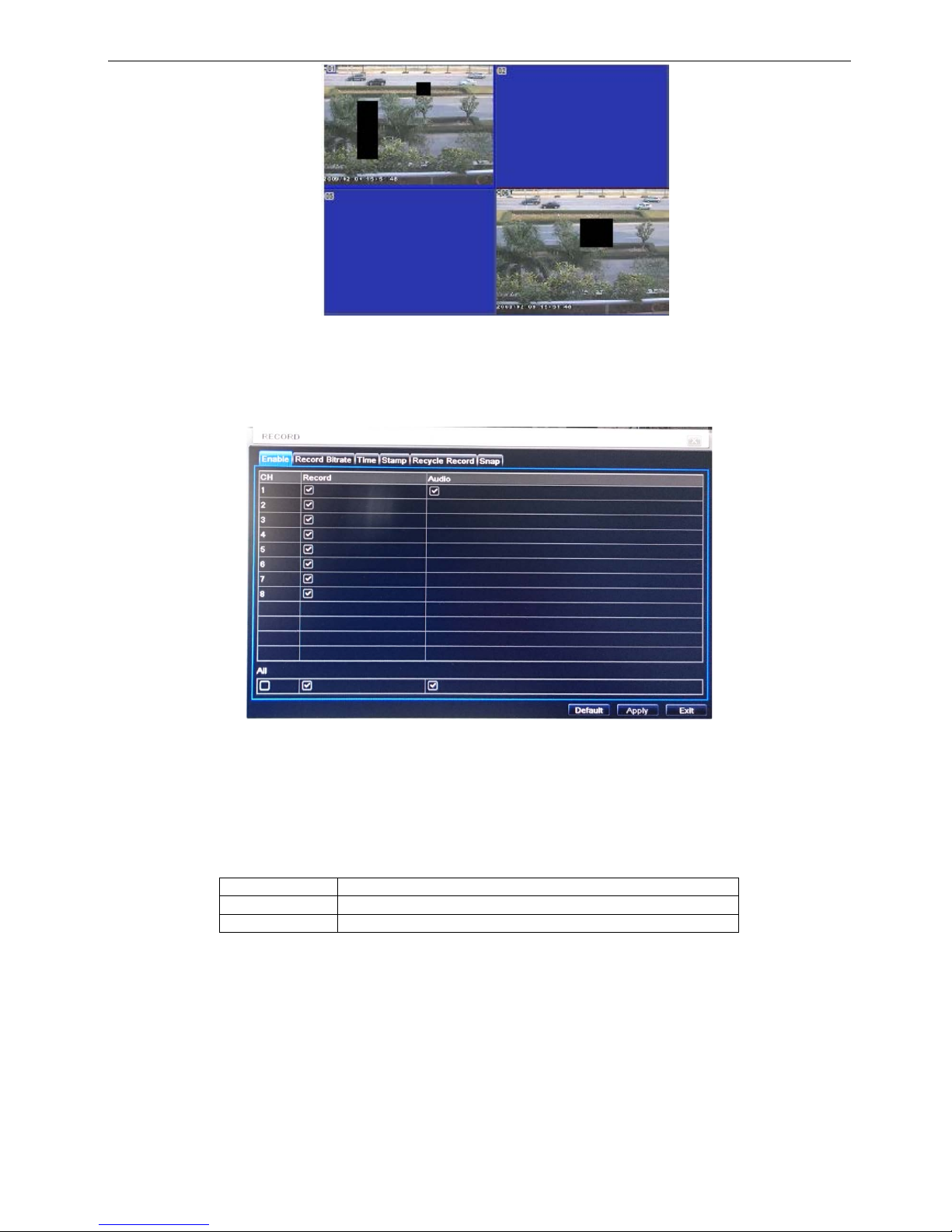
TVD-04 / TVD-08 / TVD-16 / TVD -16-1U User’s Manual
17
Live image mask area
3.3 Record configuration
Record configuration includes five sub menus: enable, record bit rate, time, recycle record and stamp.
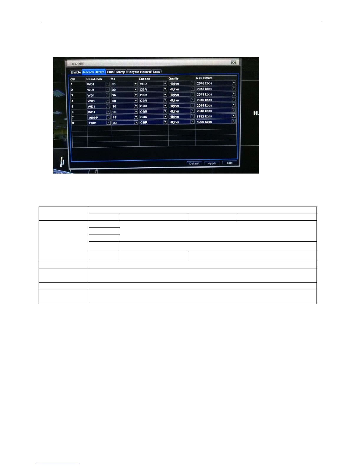
3.3.1 Enable
Step1: enter into system configurationrecord configurationenable; refer to Fig 3-10:
Fig. 3-10 record configuration-enable
Step2: tick off record, audio and record time
Step3: user can setup all channels with same parameters, tick off “all”, then to do relevant setup.
Step4: click “default” button to resort default setting; click “apply” button to save the setting; click “exit” button
to exit current interface.
Definitions and descriptions of Re cord:
Parameter
Meaning
Record
Record switch of every channels
Audio
Enable live record audio
TVD-04 / TVD-08 / TVD-16 / TVD -16-1U User’s Manual
18
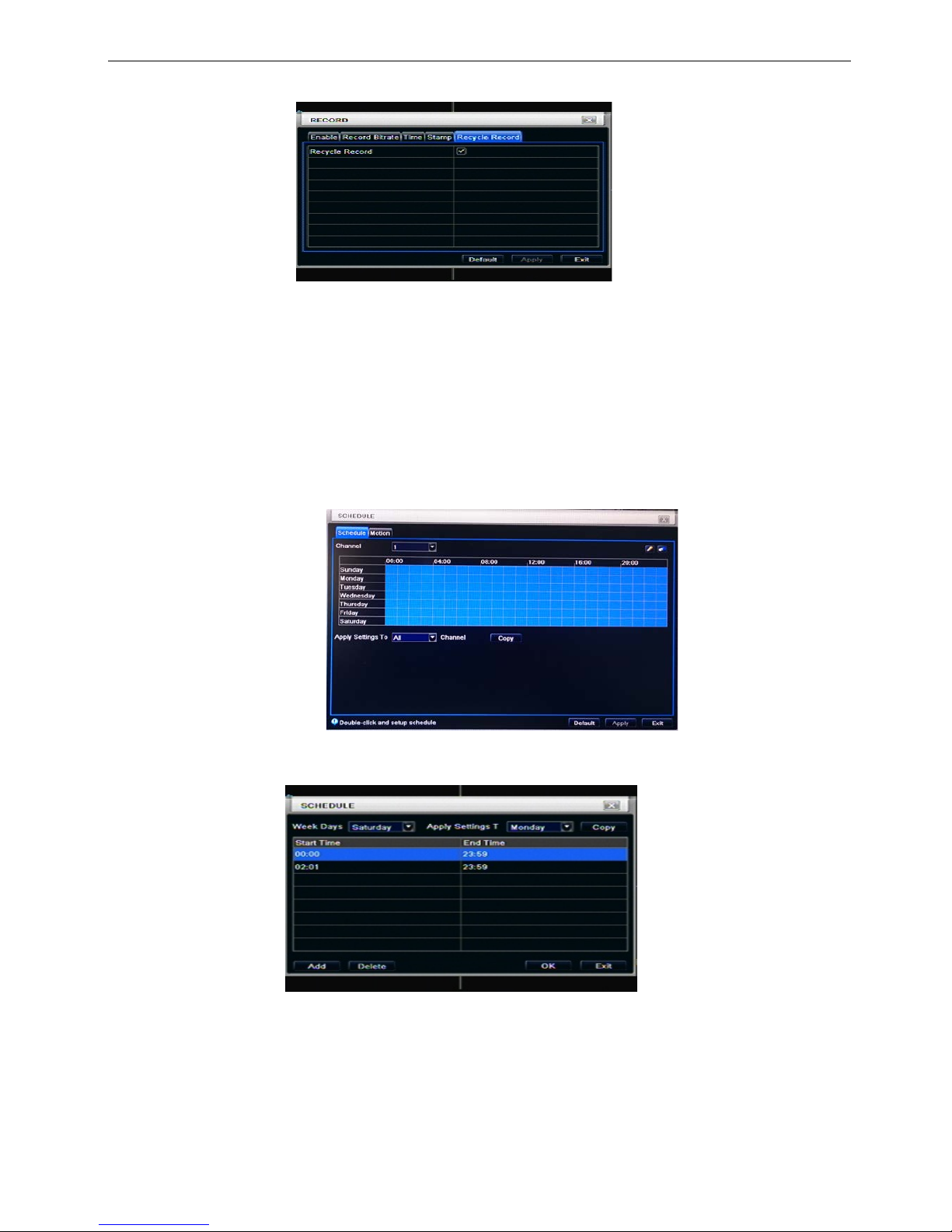
3.3.2 Record stream
Step1: enter into system configurationrecord configurationrecord bit rate
When you use the TVI Ser ies DVR, as DVR received t he s ig na l f r om camera, DVR will automatically do the
video resolution depending on camera type discrimination.
Note: if the rate value set is over high the maximum resources of the device, the value will be
adjusted automatically.
Definitions and descriptions of Re cord stream:
Parameter
Meaning
Model
4CH
8CH
16CH
Rate
960H
1-30(NTSC)/1-25(PAL)
720P
IP 720P
1080P
1-15(NTSC)/1-12(PAL)
IP 1080P
1-30(NTSC)/1-25(PAL) 1-15(NTSC)/1-12(PAL)
Resolution
This series supports 960H,720P, 1080P.
Quality
The higher the value is, the clearer the recorded image is.
Six options: lowest, lower, low, medium, higher and highest.
Encode
VBR and CBR.
Max bit stream
You shall adjust it subject to the actual network condition.
1536, 1792, 2048, 4096, 5120, 6144, 7168, 8192, 9216, 10240, 12288 kbps

TVD-04 / TVD-08 / TVD-16 / TVD -16-1U User’s Manual
19
3.3.3 Time
Step1: enter into system configurationrecord configuration time; refer to Fig 3-11:
Fig. 3-11 record configuration-time
Pre-alarm record time: the record time before event happen i. e. record time before motion detection or
sensor alarm is triggered.
Post-alarm record: set the post recording time after the alarm is finished, five options: 10s、15s、20s、30s
and 60s.
Expire time: the hold time of saved records. If the set date is overdue, the record files will be deleted
automatically.
Step2: user can setup all channels with same parameters, tick off “all”, then to do relevant setup.
Step3: click “default” button to resort default setting; click “apply” button to save the setting; click “exit” button
to exit current interface.
3.3.4 Stamp
Stamp:User can overlap the channel name and time stamp on video.
Step1: enter into system configuration record configuration stamp; refer to Fig 3-12:
Fig. 3-12 record configuration-stamp
Step2: tick off camera name, time stamp; click Set button, user can use cursor to drag the camera name and
time stamp in random positions, refer to below Figures:
Before drag after drag
Step3: user can setup all channels with same parameters, tick off “all”, then to do relevant setup.
Step4: click “default” button to resort default setting; click “apply” button to save the setting; click “exit” button
to exit current interface.
TVD-04 / TVD-08 / TVD-16 / TVD -16-1U User’s Manual
20
3.3.5 Recycle record
Step1: enter into system configurationrecord configurationrecycle record;
Step2: tick off recycle record, the recycle record f unction will enabl e, it will cover the e arlier recorded files
and keep recoding when HDD is full; if disenable this function, it will stop recording when HDD is full.
Step3: click “default” button to reset default setting; click “apply” button to save the setting; click “exit” button
to exit current interface.
3.4 Schedule configuration
Schedule configuration includes three sub menus: schedule, and motion.
3.4.1 Schedule
The volume means the se ven days of a week from Monda y to Sunday, the row means 24 hours of a da y.
Click the grid to do relevant setup. Blue means checked area, gray means unchecked area.
Step1: enter into system configurationschedule configurationschedule; refer to Fig 3-13:
Fig. 3-13 schedule configuration-schedule
Step2: select channel, double-click and a dialog box will pop-up as Fig 3-14, user can edit week schedule:
Fig. 3-14 schedule-week schedule
① Click “add” button to add a certain day schedule; click “delete” button to delete the selected schedule;
Copy: user can copy the specify schedule to other dates.
Click “OK” button to save the setting, click “Exit” button to exit current interface.
② User can apply the schedule setting of certain channel to other or all channels, just only select channel
and click “Copy” button.
Step3: click “default” button to resort default setting; c lick “apply” button to save the se tting; click “exit”
button to exit current interface.
TVD-04 / TVD-08 / TVD-16 / TVD -16-1U User’s Manual
21
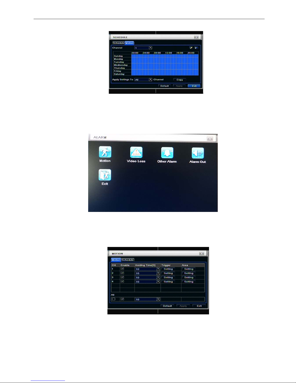
3.4.2 Motion
Step1: enter into system configurationschedule configurationmotion; refer to Fig 3-15:
Fig. 3-15 schedule configuration-motion
Step2: the setup steps of motion are familiar with schedule; user can refer to 4.4.1 Schedule for details.
Note: the default schedule of motion detection is full-selected, that is, the color of schedule setting
interface is blue.
3.5 Alarm configuration
Alarm configuration includes five sub menus: motion, video loss, other alarm and alarm out.
Fig 3-16 alarm configuration
3.5.1 Motion
Motion includes two sub menus: motion and schedule.
① Motion
Step1: enter into system configurationalarm configurationmotion; refer to Fig 3-17:
Fig 3-17 alarm configuration-motion
 Loading...