

Okina Professional H.264, Professional H.264 DVR Setup Manual
Professional H.264 DVR
Setup Guide
Package Content
Inspect the packaging carton. Make sure your Professional H.264 DVR is properly delivered.
Remove all items from the box and make sure the box contains the following items.
Professio n al H.264 DVR Power Cord Software CD-CMS User’s Manual
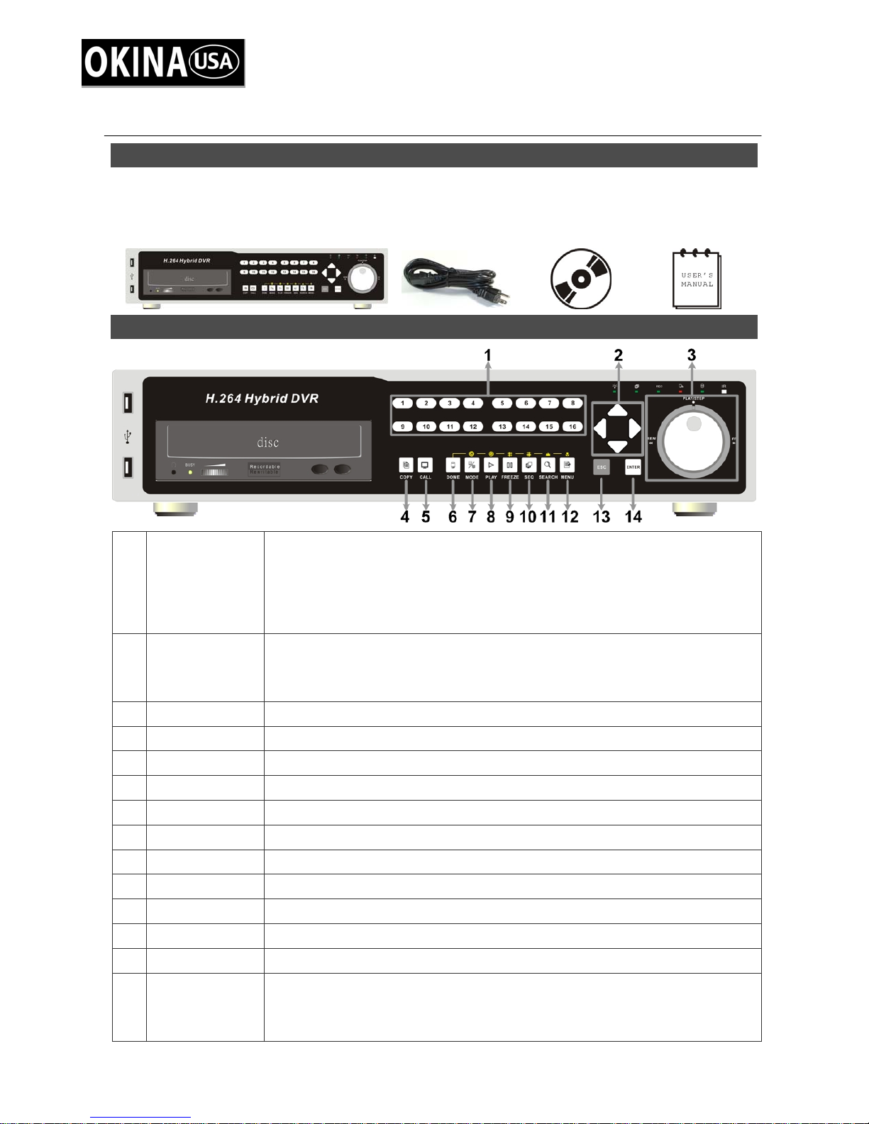
Front Panel
1 Channels
2 Direction Keys
3 Shuttle/ Jog
1. In Live and Playback modes, press any key to view the corresponding
video in full-screen.
2. In input interface, 1~10 can be used for direct input of numbers 0~9.
3. In Dome Camera Control mode, 1 is for entering the Set/ Go preset
menu; 2 is for hiding or displaying the dome setting parameters; 11~16
is for quick access of preset points 1~6.
1. In Zoom mode, these keys function as normal direction keys.
2. In the OSD setup menu, the direction keys are used to move the cursor
to previous or next fields. To change the value in the selected field,
press UP / DOWN keys.
This is used to control playback operations.
4 COPY
5 CALL
6 DOME
7 MODE
8 PLAY/STOP
9 FREEZE
10 SEQ
11 SEARCH
12 MENU
13 ESC
14 ENTER
00P5DG600ZLEA1 1
This key is used for marking time in ezBurn™ function.
Press this key to control call monitor or 2nd main monitor.
Press this key to enter Dome Camera Control mode.
Press this key to view in full-screen or multiple window modes.
Press once to start the playback of recorded video. Press again to exit.
Press this key to freeze the current viewing screen.
Press this key to start automatic sequence display of cameras.
Press this key to search recorded video by date/time or event.
Press this key to enter the OSD setup menu.
Press this key to cancel or exit from certain control mode.
1. In OSD menu or selection interface, press these key to make the
selection or save settings.
2. In live full-screen viewing mode, press this key to view a 2× zoom
image; press it again to return.

Back Panel
Main Monitor
1
Audio Out
Main Monitor
2
(BNC)
A RCA connector is provided to output audio associated with the
main monitor.
A BNC connector is provided for connecting to a main monitor.
3 Call Monitor (BNC) A BNC connector is provided for connecting to a call monitor.
A group of BNC connectors is offered for video input streams from
4 Video In (BNC)
installed cameras. The number of connectors equals to the number
of channels.
5 Video Out (BNC)
Main Monitor
6
(S-Video)
7 Audio In
Main Monitor 1
8
(VGA)
Main Monitor 2
9
(VGA)
10 Alarm I/O & RS-485
11 NAS Device
The same amount of BNC connectors underneath Video IN (BNC)
is offered for looping out the video input.
An S-Video connector is provided for connecting to a main monitor.
The DVR provides audio in connectors (a terminal block) for each
channel to connect its individual audio source device.
Two VGA output connectors are offered for connecting to VGA
main monitors 1 & 2 respectively. The source image is the same as
BNC & S-Video connectors.
The DVR provides alarm I/O and RS-485 ports that offer users the
flexibility required to connect the unit to other devices.
The NAS connector allows users to connect to a Network-Attached
Storage (NAS) device to expand HDD capacity of the DVR.
Two USB 2.0 ports are located on the rear panel for users to
12 USB 2.0 Ports (×2)
connect external USB devices to the unit, such as ThumbDrive® or
a USB mouse.
LAN 10/100/1000M
13
(RJ-45)
14 RS232
Audio Out
15
(Optional)
The DVR is capable of networking and it allows the videos to be
viewed over the LAN network or the Internet by using the Internet
Explorer.
The DVR provides a RS232 communication port for sending and
receiving signals.
Optional Audio Out connectors can be installed for each channel to
connect its individual audio output device.
16 Power Switch Use this switch to power on / off the DVR.
17 Power Jack
Connect the power supply cord shipped with the DVR. Use of other
power supply cords may cause overloading.
NOTE: The BNC and VGA monitor cannot coexist at the same time under normal condition.
Switching off VGA1 connector will allow BNC and VGA monitor to be shown simultaneously.
Refer to the OSD Setup Manual for detail settings.
2
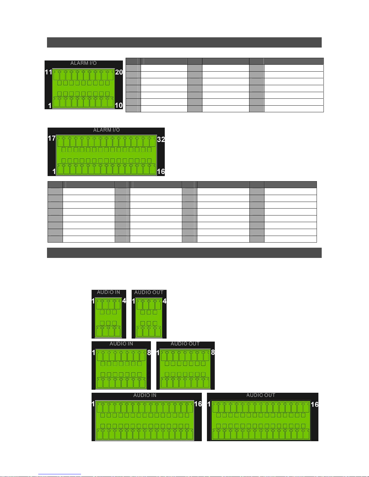
Pin Definition of Alarm I/O & RS-485
4ch-Model / 8ch-Model:
Pin Definition Pin Definition Pin Definition
1
RS485 D+
2
RS485 D−
3
Ground
4
Normal Close A
5
Common Node A
6
16ch-Model:
Normal Open A
7
Ground
8
Normal Close B
9
Common Node B
10
Normal Open B
11
Alarm In 1
12
Alarm In 2
13
Alarm In 3
14
Alarm In 4
15
Alarm In 5 (8ch model)
16
Alarm In 6 (8ch model)
17
Alarm In 7 (8ch model)
18
Alarm In 8 (8ch model)
19
N/A
20
N/A
Pin Definition Pin Definition Pin Definition Pin Definition
1
RS485 D+
2
RS485 D−
3 Ground 11 Ground 19 Alarm In 3 27 Alarm In 11
4
Normal Close A
5
Common Node A
6
Normal Open A
7
Ground
8
Normal Close B
9
Common Node B
10
Normal Open B
12
Normal Close C
13
Common Node C
14
Normal Open C
15
Ground
16
Ground
17
18
20
21
22
23
24
Alarm In 1
Alarm In 2
Alarm In 4
Alarm In 5
Alarm In 6
Alarm In 7
Alarm In 8
25
26
28
29
30
31
32
Alarm In 9
Alarm In 10
Alarm In 12
Alarm In 13
Alarm In 14
Alarm In 15
Alarm In 16
Pin Definition of Audio In / Audio Out
For terminal blocks of Audio In and Audio Out, shown as below pictures, pins on the upper row are
Audio In / Audio Out connectors for all channels, in sequential order from left to right. All other pins
on the bottom row are for ground connection.
4ch-Model:
8ch-Model:
16ch-Model:
3
 Loading...