

Okina P3D-E48, P3ID17-E48, PD-E5343, PID17-E5343 Operational Manual

3x PTZ Series
P3D-E48
P3ID17-E48
PT Series
PD-E5343
PID17-E5343
Also Available for 6.0mm Lens , PD-E5360 & PID17-E5360
3x Pan/Tilt/Zoom Indoor Mini Dome Camera
3x Pan/Tilt/Zoom Indoor Mini Dome Camera w/ 17 IR
Pan/Tilt Indoor Mini Dome Camera w/ 4.3mm Lens
Pan/Tilt Indoor Mini Dome Camera w/ 4.3mm Lens w/ 17 IR
OPERATIONAL MANUAL
INDOOR MINI DOME CAMERA
3x PTZ
P3D-E48
P3ID17-E48
Copyright © 2009. All Rights Reserved.
PAL Version Also Available
http://www.okinausa.com 1 REV081709
Please read the Operational Manual
before attempting to use this product.
PT Only
PD-E5343
PID17-E5343
FEATURES
P3D-E48 & P3ID17-E48
• 1/4” Sony Super HAD CCD
• 480 TV Lines
• 17 IR LED – P3ID17
• IR Distance up to 30ft – P3ID17
• Pentax 3x Optical Zoom Lens
f=2.8mm~7.3mm
• Pan Speed: 8°~80° per sec
• Tilt Speed: 8°~80° per sec
• Pan Angle 0°~355°, Tilt Angle: 0°~90°
• 32 Preset Points
• 1.0 Lux @ F2.0
• Protocols Selected by DIP Switch
• RS485 Interface
• 0~255 ID Address
• 12V DC, 1000mA
PD-E5343 & PID17-E5343
• 1/3” Sony Super HAD CCD
• 530 TV Lines
• 17 IR LED – PID17
• IR Distance up to 30ft – PID17
• 4.3mm Fixed IR Lens*
Also Available for 6.0mm Lens
• Pan Speed: 8°~80° per sec
• Tilt Speed: 8°~80° per sec
• Pan Angle 0°~355°, Tilt Angle: 0°~90°
• 32 Preset Points
• 0.8 Lux @ F2.0
• Protocols Selected by DIP Switch
• RS485 Interface
• 0~255 ID Address
• 12V DC, 1000mA
*IR Lens = IR Corrected Type Lens
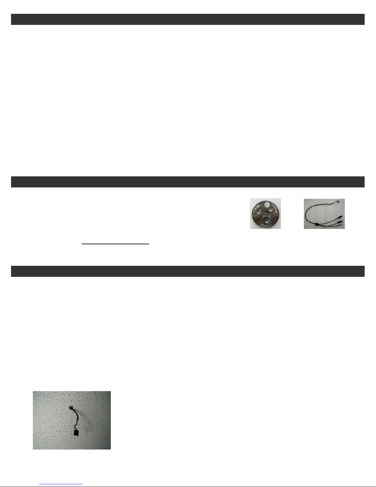
PACKAGE CONTENTS
• One (1) P3D-E48 / P3ID17-E48 / PD-E5343 or PID17-E5343 Camera
• One (1) Quick Installation Plate
• One (1) Signal-Power Cable
• One (1) Operational Manual
* For any returns, please include all components listed above with
original packaging in Resalable Condition
. Absolutely No
Quick Installation Plate
Signal-Power Cable
Returns will be accepted if any component is missing/damaged.
INSTALLATION
Step 1:
Setting of Camera Position Code
Prior to installation, setup ID address and communication protocol of your camera first, then you can install it (refer to
page 5 for more details). If resetting of ID or protocol is necessary after installation, please POWE R-O FF the camer a
before resetting. The new setting will become valid after power is reapplied to the camera.
Step 2:
On the Signal-Power cable, different wires have been labeled with its function: one for Video Output, one for RS485
input and one for 12V DC power input. Please follow these labeling for your correct wiring. There are two installation
methods which you can choose from.
Method 1:
Decide the location where you want to install and then drill one hole with about 2 cm in diameter. Insert
Signal-Power cable through this hole as below:
Copyright © 2009. All Rights Reserved.
http://www.okinausa.com 2 REV081709
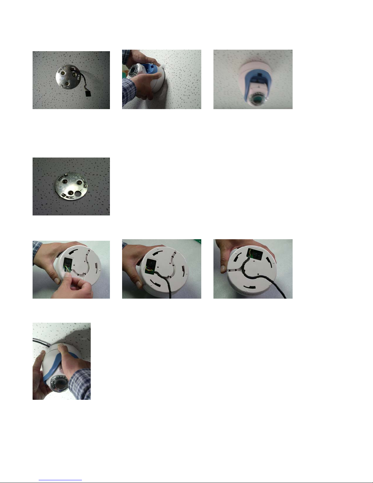
Then take out the quick-installation plate which is provided inside the accessory bag. Again insert the Signal-
g
Power cable through any round holes of the quick-installation plate and screw it into the platform as shown in
photo A below. Connect the Signal-Power cable to the camera. Twist the base of the dome camera into the
quick-installation plate as shown in photo B. Refer to photo C for completed installation.
(photo A) (photo B) (photo C)
Method 2:
Take out the quick-installation plate which is provided from the accessory bag. Screw the quick-installation
plate into the location where you want to install, as shown below:
Connect the Signal-Power cable into the base of the camera as shown in photo A. There are two wiring
direction choices which you can choose from, as shown in photo B and photo C.
(photo A) (photo B) (photo C)
Twist the base of the camera into the quick-installation plate, and the installation is done.
*Make sure the camera is locked on
securely to prevent any risk of the camera
fallin
.
Copyright © 2009. All Rights Reserved.
http://www.okinausa.com 3 REV081709
Step 3:
Power On Test
a. Before connecting the power, make a final check to confirm that the wiring is correct.
b. Before installing this camera, please execute camera self-testing as following: when powering on the camera,
it will automatically execute tilt up/down scanning, then pan horizontal scanning for around 20~30 seconds,
then camera will stop at the Preset Point 1. Upon completion of these, the speed dome camera is in normal
condition.
NOTE: This product is normally installed in an elevated position. Installation work should comply with local safe
regulations. Proper safety precautions and protective measures shall be taken for installing the camera. For the
personnel safety’s sake, carry out power on and product test only after completion of installation work.
USING IR REMOTE CONTROL
This camera has built-in IR Receiver, which will allow user to use our IR Remote Controller (Model: PTZ-IR10, optional
device) to control the movement of Mini Speed Dome Camera. (The operation of such IR Remote Controller can be
found on the user’s manual of PTZ-IR10)
RS485 WIRING METHOD
Two RS485 wiring methods can be used according to actual needs. We recommend the following wiring methods to
avoid malfunction of RS485 control.
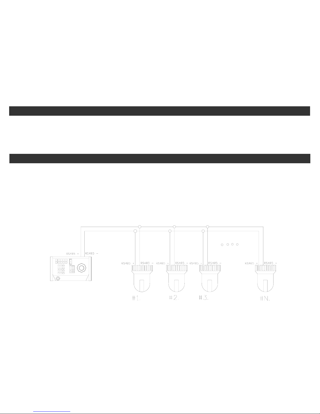
1. RS485 serial connection:
This method connects the dome cameras in sequential manner where the first camera connects to the second and
then the second to the third, and so on until the last one is connected. A terminal resistance is connected to the
last camera to form a closed loop. See the following illustration:
PELCO
Control Keyboard
When using RS485 serial connection, the max. in one serial connection is to connect up to 32 pieces of speed
dome. If over 32 pieces of speed dome, please use “RS485 Aster Connection” method together with our DS810 (8
port RS485 distributor) to diversify the number of speed domes in one single serial connection in order to make
sure the stability of the complete control system.
2. RS485 Aster Connection:
This is the most common method in practical installation work. In the aster connection, if an RS485 distributor is
not utilized, it is likely to have reflected signal and to lower the ability of resisting interference. This may cause
malfunctioning of the control signal that results in faulty control of the camera or unstopping operation when the
control signal is stopped.
Copyright © 2009. All Rights Reserved.
http://www.okinausa.com 4 REV081709
In such cases, we recommend to use our DS810 RS485 Distributor. This product can effectively convert the aster
connection into the correct connection method that meets RS485 requirements to acquire optimal communication
reliability. See the following diagram for reference.
PELCO
Control Keyboard
COMMUNICATION PROTOCOL & ID ADDRESS SETTING
NOTE: Please POWER-OFF the camera before resetting. The new setting will become valid after power is reapplied to
the camera.
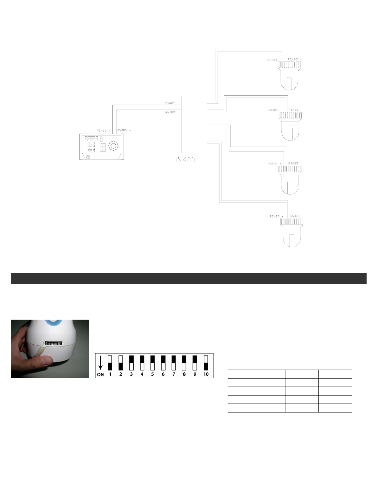
Open the plastic cover (as shown below) on the back-side of the camera.
You will find one 10-PIN DIP SWITCH. SW9/10 is for setting the
camera’s protocols.
1. Setting for Communication Protocol
DIP 9 DIP 10
OKINA USA ON ON
PELCO P-9600 OFF ON
PELCO P-4800 ON OFF
PELCO D-2400 OFF OFF
Copyright © 2009. All Rights Reserved.
http://www.okinausa.com 5 REV081709
 Loading...