

Okina HDRS-04-1U, HDRS-08-2U, HDRS-16-2U User Manual

DV-8_HDRS-04-1U / DV-9_HDRS-08-2U / DV-10_HDRS-16-2U User’s Manual
R201304-V10
HDRS-04-1U /
HDRS-08-2U /
HDRS-16-2U
4 / 8 / 16 CH. HD SDI
H.264 DVR

DV-8_HDRS-04-1U / DV-9_HDRS-08-2U / DV-10_HDRS-16-2U User’s Manual
R201304-V10
2
CAUTION
Please read this user manual carefully to ensure that you can use the device correctly and safely
We do not warrant all the content is correct. The contents of this manual are subject to change
without notice
This device should be operated only from the type of power source indicated on the marking label.
The voltage of the power must be verified before using. If not in use for a long time, pull out the plug
from the socket
Do not install this device near any heat sources such as radiators, heat registers, stoves or other
device that produce heat
Do not install this device near water. Clean only with a dry cloth
Do not block any ventilation openings . And ensure well ventilation around the machine
Do not power off the DVR at normal recording co nditio n! The correct operation to shut off DVR is to
stop recording firstly, and then se le ct “s hut-down” button at the rig ht of t he me nu bar to e xit, and fi nal ly
to cut off the power.
This machine is indoor using equipment. Do not expose the machine in rain or moist environment. In
case any solid or liquid get into the machine’s case, please cut off the power supply immediately, and
ask for qualified technicians to check the machine before restart
Refer all servicing to qualified service personnel. No any parts repaired by yourself without technical
aid or approval.
This manual is suitable for 4, 8, 16 channel HD digital video recorders.
1. Panel Definition
1.1 Front Panel – 4 CH.
1.2 Back Panel – 4 CH.
1.3 Front Panel – 8 / 16 CH.
1.4 Back Panel – 8 / 16 CH.
2. Control Option
2.1 Remote Controller – 4 CH.
2.2 Remote Controller – 8 / 16 CH.
2.3 Mouse Control
3. Basic Function Instruction
3.1 Power On/Off
3.2 Power On
3.3 Power Off
3.4 Login
3.5 Live Preview
3.6 Live Playback
4. Main Menu Setup Guide
4.1 Basic Configuration
4.1.1 System
4.1.2 Time & Date
4.1.3 DST
4.2 Live Configuration
4.2.1 Live
4.2.2 Main Monitor
4.2.3 SPOT
4.2.4 Mask
Index

DV-8_HDRS-04-1U / DV-9_HDRS-08-2U / DV-10_HDRS-16-2U User’s Manual
R201304-V10
3
4.3 Record Configuration
4.3.1 Enable
4.3.2 Record Stream
4.3.3 Time
4.3.4 Stamp
4.3.5 Recycle Record
4.4 Schedule Configuration
4.4.1 Schedule
4.4.2 Motion
4.4.3 Sensor
4.5 Alarm Configuration
4.5.1 Sensor
4.5.2 Motion
4.5.3 Video Loss
4.5.4 Other Alarm
4.5.5 Alarm Out
4.6 Network Configuration
4.6.1 Network
4.6.2 Network Stream
4.6.3 Email
4.6.4 Other Setting
4.7 User Management Configuration
4.8 P.T.Z Configuration
5. Record Search & Playback and Backup
5.1 Time Search
5.2 Event Search
5.3 File Manager
5.4 Backup
6. Manage DVR
6.1 Check System Information
6.1.1 System Information
6.1.2 Event Information
6.1.3 Log Information
6.1.4 Network Information
6.1.5 Online Information
6.1.6 Manual Alarm
6.1.7 Disk Manager
6.1.8 Upgrade
6.1.9 L ogoff
6.1.10 Shut Down
7. Remote Surveillance
7.1 Accessing DVR
7.1.1 On Lan
7.1.2 On WAN
7.2 The Remote Live Preview Interface as Below
7.3 Remote Playback & Backup
7.3.1 Remote Playback
7.3.2 Remote Backup
7.4 Remote System Configuration
7.5 Remote Management
8. Mobile Surveillance
8.1 Installation Procedure on IPhone Device
8.2 Installation Procedure on Android OS Smartphone
9. Appendix
9.1 Appendix A – FAQ
9.2 Appendix B – Calculate Recording Capacity
10. DDNS Setup Procedure – Take DynDNS as an Example
Index
DV-8_HDRS-04-1U / DV-9_HDRS-08-2U / DV-10_HDRS-16-2U User’s Manual
R201304-V10
4
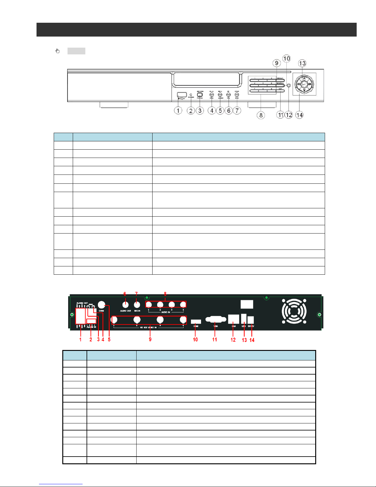
1.1 Front Panel – 4 CH.
Notice: The pictures are only for reference; please make the object as the standard.
Front Panel of 4 CH HD DVR
No
Label Name
Description
1
USB
Connect USB thumb drive
2
POWER
Power indicator
3
REC / FOCUS
Manual record / FOCUS adjustment(PTZ)
4
Play / IRIS
Enter Playback/ IRIS adjustment (PTZ)
5
REW / ZOOM
REW on playback mode / ZOOM adjust me nt (PTZ)
6
FF / P.T.Z.
FF on playback mode /Enter PTZ mode
7 STOP / ESC
STOP playback on playbac k mode /
Exit MENU or jump back to previous page
8
Digital
Enter digital or select channel
9
MENU / +
Enter MENU page / increase value
10
SEARCH / -
Enter SEARCH page / decrease value
11 10+
To enter digital over 10 /
Continuously press twice to have 10
12
IR receiver
Remote receiver
13
Enter
Enter
14
Split / Directi on Key
Switch split / Move selected item
1.2 Back Panel – 4 CH.
Rear Panel for 4-ch HD DVR
Item Name Description
1
Alarm out
4-ch relay output. Connect to external alarm.
2
Alarm in
Alarm inputs. Connect to external sensors
3
P/Z
Connect to speed dome
4
K/B Controller
Connect to keyboard Controller
5
CVBS port
CVBS video signal output
6
Audio out
Audio output, connect to the sound box
7
MIC IN
Talk. Connect to microphone.
8
Audio in
4-ch Audio inputs
9
HD SDI Video In
4-ch video inputs
10
HDMI port
Connect to high-definition display device
11
VGA port
VGA output, connect to monitor
12
LAN
Network port
13 USB port
To connect external USB dev i ces lik e U SB flas h, US B H DD or U SB mous e .
Recommend using for USB mouse
14
DC 12V
Power input
1. Panel Definition
DV-8_HDRS-04-1U / DV-9_HDRS-08-2U / DV-10_HDRS-16-2U User’s Manual
R201304-V10
5
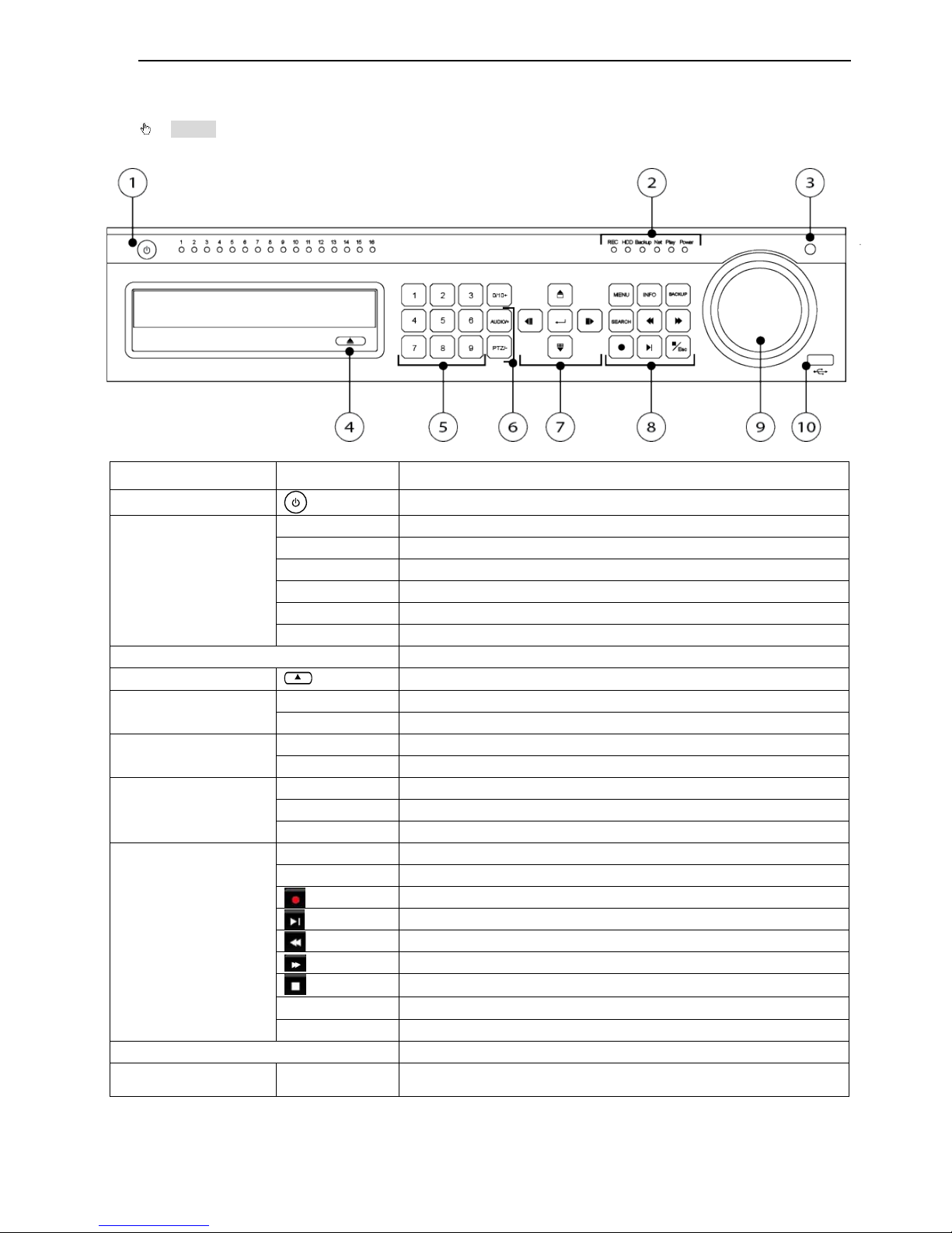
1.3 Front Panel – 8 / 16 CH.
Notice: The pictures are only for reference; please make the object as the standard.
1. The Front Panel interface for 8 / 16 channel HD Hybrid H.264 DVR is shown as below:
Item # Label Name Function
1
Power Switch
Power on/off
2
Work state indicator
REC When recording, the light is blue
HDD When HDD is writing and reading , the light is blue
Backup When backup files and data, the light is blue
Net When access to network , the light is blue
Play When playing video, the light is blue
Power Power indicator, when connection , the light is blue
3
IR receiver
Remote receiver
4
Eject Button
Eject DVD
5
Digital Button
1-9 Input number 1-9 or choose camera
0/10+ Input number0, 10 and the above number together with other digital keys
6
Compound Button
P.T.Z./- 1. Enter PTZ mode in live 2. Decrease the value in setup
AUDIO/+ 1. Control voice 2. Increase the value in setup
7
Input button
Direction button Change direction to select items
Multi-screen Change screen display mode like1/4/9/16 cha nnel
Enter button Confirm selection
8
Function button
MENU Ent er menu in live
INFO Check recording data
Record manually
Play/Pause
Rewind
Fast forward
/Esc
Exit/ESC
BACKUP Enter backup mode in live
SEARCH Enter search mode
9 Split / Direction Key Switch split / Move selected item
10 USB USB port
To connect external USB devices like USB flash, USB HDD for backup or
update firmware;
DV-8_HDRS-04-1U / DV-9_HDRS-08-2U / DV-10_HDRS-16-2U User’s Manual
R201304-V10
6
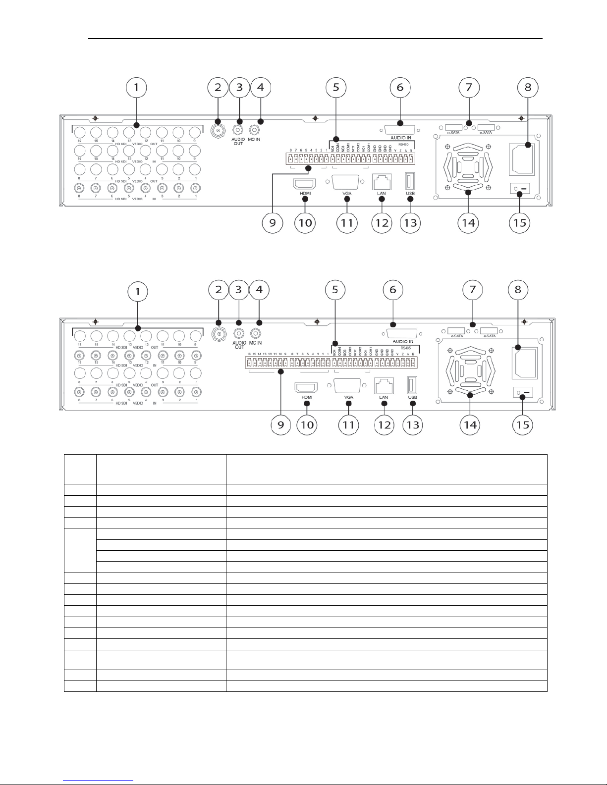
1.4 Back Panel – 8 CH.
1.5 Back Panel – 16 CH.
Item
#
Label Name Function
1
HD SD Video in / out
HD SDI video signal inputs
2
CVBS
CVBS output
3
Audio out
Audio output, connect to the sound box
4
MIC in
Talk. Connect to microphone
5
Alarm out
Relay Output. Connect to external alarm
GND
Grounding
K/B Controller
Connect to keyboard Controller. A is TX+, B is TX-
P/Z
Connect to speed dome. Y is TX+, Z is TX-
6
Audio in
Audio input
7
eSATA
Connect to External HDD for backup
8
POWER INPUT
AC 110V-220V
9
Alarm in
Alarm Inputs for connecting sensors
10
HDMI port
Connect to high-definition display device
11
VGA port
VGA output, connect to monitor
12
LAN
Network port
13 USB port
To connect external USB devices like USB flash, USB HDD or USB mouse.
Recommend using for USB mouse
14
FAN
For cooling the device
15
POWER SWITCH
Switch on/off
DV-8_HDRS-04-1U / DV-9_HDRS-08-2U / DV-10_HDRS-16-2U User’s Manual
R201304-V10
7
1.6
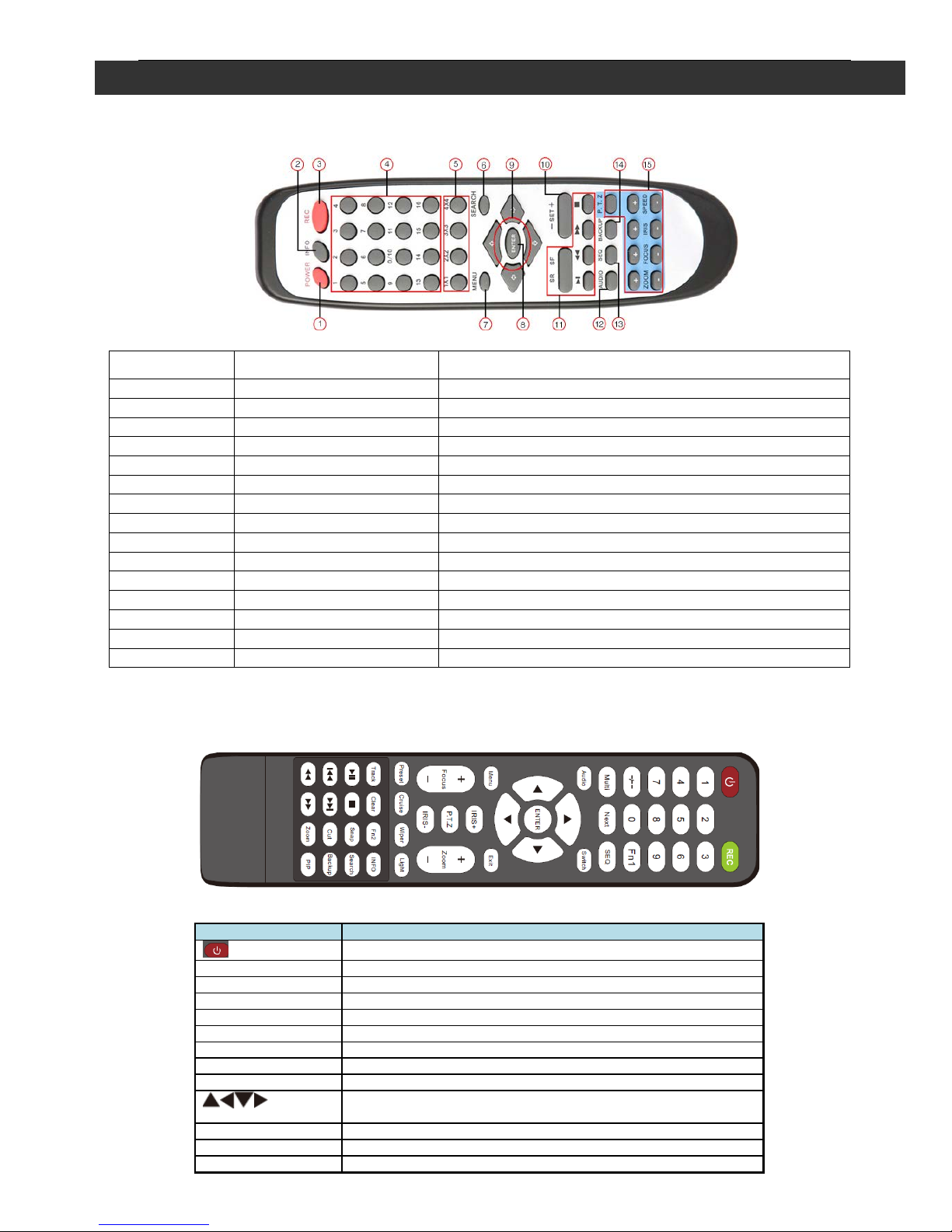
2.1 Remote Controller – 4 CH.
◆ This remote control uses AAA battery, the definition as following:
Item # Label Name Function
1
Power
System shut down
2
INFO
Enter information page
3
REC
Manual record
4
Digital Button
Enter digital or switch channel
5
Split Screen
Switch split screen
6
SEARCH
Enter search mode
7
MENU
Enter Mode
8
ENTER
Enter
9
Direction Button
Move item or PTZ direction
10
+/-
Add or reduce value
11
Playback Control
Playback control FF/REW/STOP/STEP
12
AUDIO
Live audio switch
13
SEQ
Sequence
14
BACKUP
Enter Backup mode
15
PTZ Control
Control PTZ Zoom/Focus/Iris/Speed
2.2 Remote Controller – 8 / 16 CH.
◆ This remote control uses AAA battery, the definition as following:
Button
Function
Power Button
Switch off—to stop DVR. Use it before turning off the power
Record Button
To record manually
-/-- /0-9 Digital Button
Input number or choose camera
Fn1 Button
Unavailable temporarily
Multi Button
To choose multi screen display mode
Next Button
To switch the live image
SEQ
To enter into auto dwell mode
Audio
To enable audio output in live mode
Switch
To switch the output between BNC and VGA
Direction button
To move cursor in setup or pan/title PTZ
Enter Button
To confirm the choice or setup
Menu Button
To enter into menu
Exit Button
To exit the current interface
2. Control Option

DV-8_HDRS-04-1U / DV-9_HDRS-08-2U / DV-10_HDRS-16-2U User’s Manual
R201304-V10
8
Focus/IRIS/Zoom/PTZ
To control PTZ camera. Move camera/zoom/IRIS/Focus
Preset Button
To enter into preset setting in PT Z mode
Cruise Button
To enter into cruise setting in PTZ mode
Track Button
To enter into track setting in PTZ mode
Wiper Button
To enable wiper function in PTZ mode
Light Button
To enable light function in PTZ mode
Clear Button
To return to the previous interface
Fn2 Button
Unavailable temporarily
Info Button
Get information about DVR like firmware version, HDD information
To control playback. Play/Pause/Stop/Previous Section/Next
Section/Rewind/Fast Forward
Snap Button
To take snapshots manually
Search Button
To enter into search mode
Cut Button
To set the start/end time for backup in playback mode
Backup Button
To enter into backup mode
Zoom Button
To zoom in the images
PIP Button
To enter into picture in picture setting mode
◆ Switch Remote Control ID
1. Take remote control and point to DVR then continuously press “8”,”8”,”ID(0-65535)”,”Enter”.
2. Make change on DVR ID Setting,
Go to “SYSTEM MENU” > “DEVICE I D” to make change
*The ID must be the same on DVR.
*For example: If ID=1 ,
Please take remote control and point to DVR then press 8,8,1,Enter.
Then go to “SYSTEM MENU” > “DEVICE ID” change the ID=1
2.3 Mouse Control: REQUIRED
◆Connection: Recommend to connect the USB mouse to the back panel.
◆Mouse functions:
1)Under LIVE mode:
On every channel,you could double click the left button to switch FULL SCREEN and double
click again to switch back to original split mode.
On every channel,you could single click right button to popup MENU page.
2)Under MENU page:
Single click left button on any functional icon could enter the function page and Single click right
button to exit function page or jump back to previous page.
If you want to key in letter or digit, please move mouse to textbox then single click left button on
textbox. The OSD keyboard will pop up as following,
3)Under Backup mode:
Single click left button to select item, single click right button to jump back to previous page.
4)Under PTZ mode:
Single click left button to operate PTZ function, single click right button to jump back to previous
page.
DV-8_HDRS-04-1U / DV-9_HDRS-08-2U / DV-10_HDRS-16-2U User’s Manual
R201304-V10
9
3.1 Power On/Off
Before you power on the unit, please make sure all the connection is good.
3.2 Pow er on
Step1: connect with the source power; switch on the power button near the power port in the rear
panel
Step2: the device will start to boot, and the power indicator will become blue
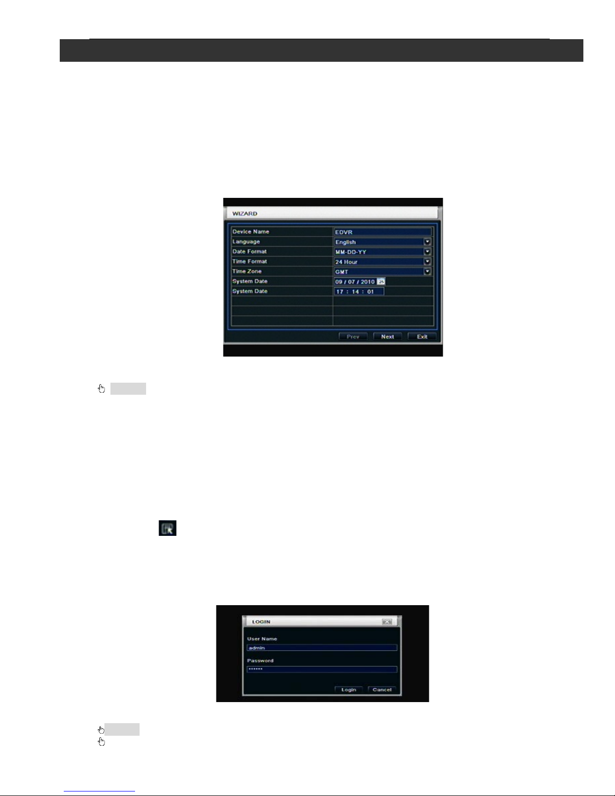
Step3: before start, a WIZARD dialogue box will pop-out (refer to below picture) and show some
information about time zone and time setup, IP information, record quick setup and HDD
information page.
After the device powers on, if there is no menu or only has live image display, user can long press ESC
button to switch.
Notice: this serial device can only display menu on VGA monitor or BNC monitor at one t ime, if
there is live image display wit hout menu display, please check up whether other device has menu
display firstly, or long press ESC key to wait f or login dialog box to app ear.
3.3 Power off
User can power off the device by using remote controller, keyboard and mouse.
By remote controller:
Step1: press Power bu tton, the shut down window will appear, click OK, the unit will power off af te r
a while.
Step2: disconnect the power
By keyboard and mouse:
Step1: enter into Menu, then select “System Shut D own” icon, the Shut down window will appear
Step2: click OK, the unit will power off after a while.
Step3: disconnect the power
3.4 Login
User can login and logout the DVR system. User cannot do any other operations except changing
the multi-screen display once logout.
Fig 3-1 Login
Notice: the default user name and password is “admin” and 123456”
The concrete oper ation steps for change password, add or delete user please r efer to User
management config ur ation for more details.
3. Basic Function Instr u cti on
DV-8_HDRS-04-1U / DV-9_HDRS-08-2U / DV-10_HDRS-16-2U User’s Manual
R201304-V10
10
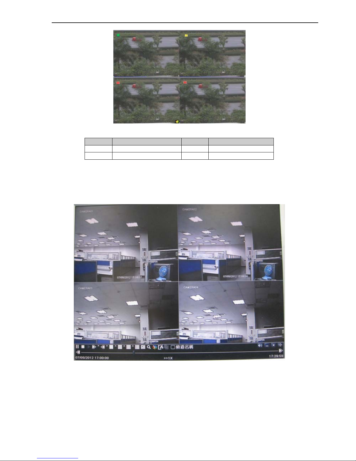
3.5 Live preview
Fig 3-2 live preview interface
The explanation of symbol in the live preview interface:
symbol
meaning
symbol
meaning
Green
Manual record
Red
Alarm in trigger record
Yellow
Motion detection record
Blue
Schedule record
3.6 Li ve playback
Click Play button to playback the recorded video. Refer to Figure3-3. User can do concrete
operation by click the buttons on screen.
DV-8_HDRS-04-1U / DV-9_HDRS-08-2U / DV-10_HDRS-16-2U User’s Manual
R201304-V10
11
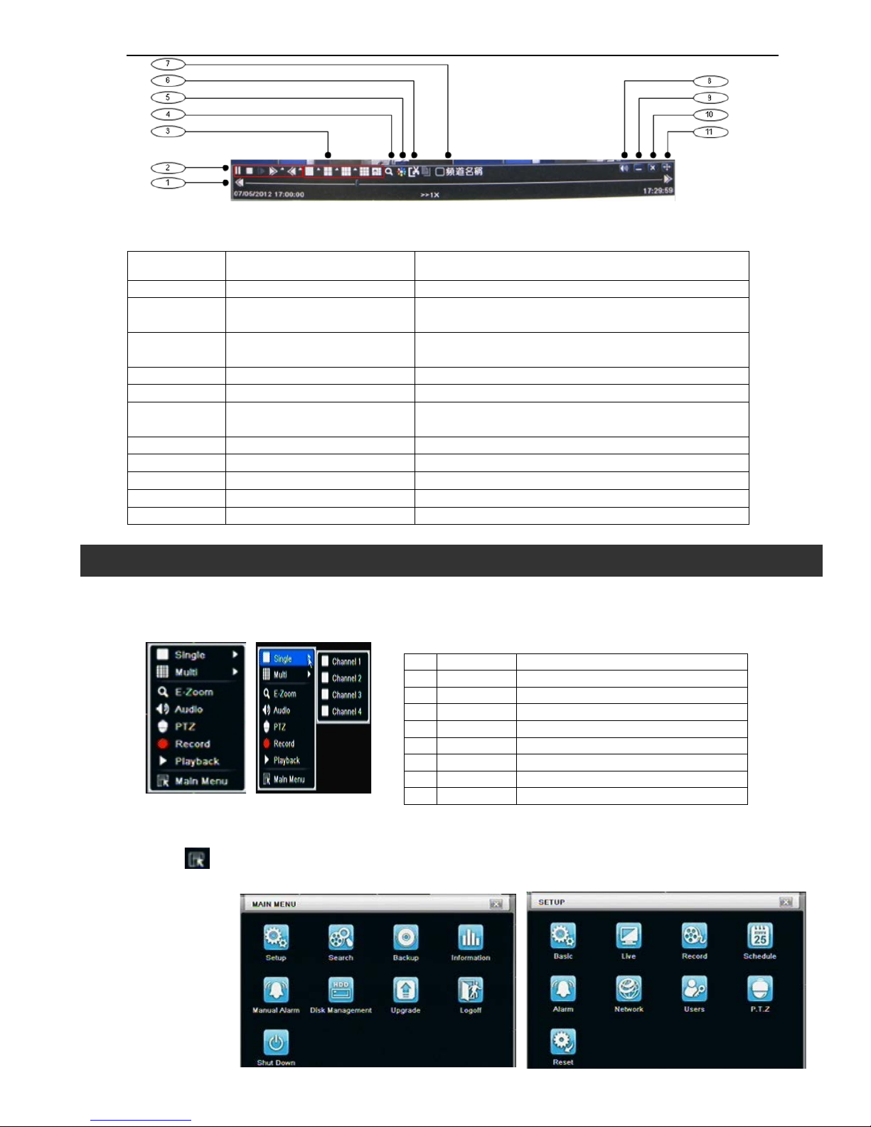
Fig 3-3 live playback
Main menu setup guide
Click right mouse or press ESC button on the front panel, the control bar will display on the screen, refer to Fig 4-1:
1
Single
Full channel
2
Multi
4ch:1/4, 8ch:1/4/9, 16ch:1/4/9/16
3
E-Zoom
Live/playback digital zoomx2
4
Audio
Audio channel setup and volume
5
PTZ
Into PTZ control mode
6
Record
Manual record
7
Playback
Playback the nearest file
8
Main Menu
Into main OSD
9
Dwell
Channel sequence(only 16CH)
Fig 4-1 main menu toolbar
Click Menu button, the interface will pop-up as Fig 4-2; pr ess MENU but ton on the fr ont panel or operate
with remote controller also can display the main menu.
Main OSD
Fig 4-2 system setup
Item Function Description
1
Playback process bar
Last/next segment of record and time process
2 Playback basic function
Play/ Pause / Stop / frame forward / fast forward /
fast rewind
3 Display mode
4ch:1/ 4, 8ch:1/ 4/ 6/ 9/ 1+5/ 1+7,
16ch:1/ 4/ 6/ 9/ 16/ 1+5/ 1+7/ 1+12
4
Zoom
Screen digital zoom x2
5
Color
Setup picture color
6 Cut
Enable to select a specific part of the video and
back it up on usb drive
7
Camera name
Enable or disable camera name display
8
Volume
Volume mute on/off
9
Reduce
Hide playback tool bar
10
Exit playback mode
11
Move the playback bar in the screen
Full channel switch, camera 1 ~ 4 or camera 1 ~ 8, camera 1 ~ 16
①
②
③
④
⑤
⑥
⑦
⑧
4. Main Menu Setup Guide
DV-8_HDRS-04-1U / DV-9_HDRS-08-2U / DV-10_HDRS-16-2U User’s Manual
R201304-V10
12
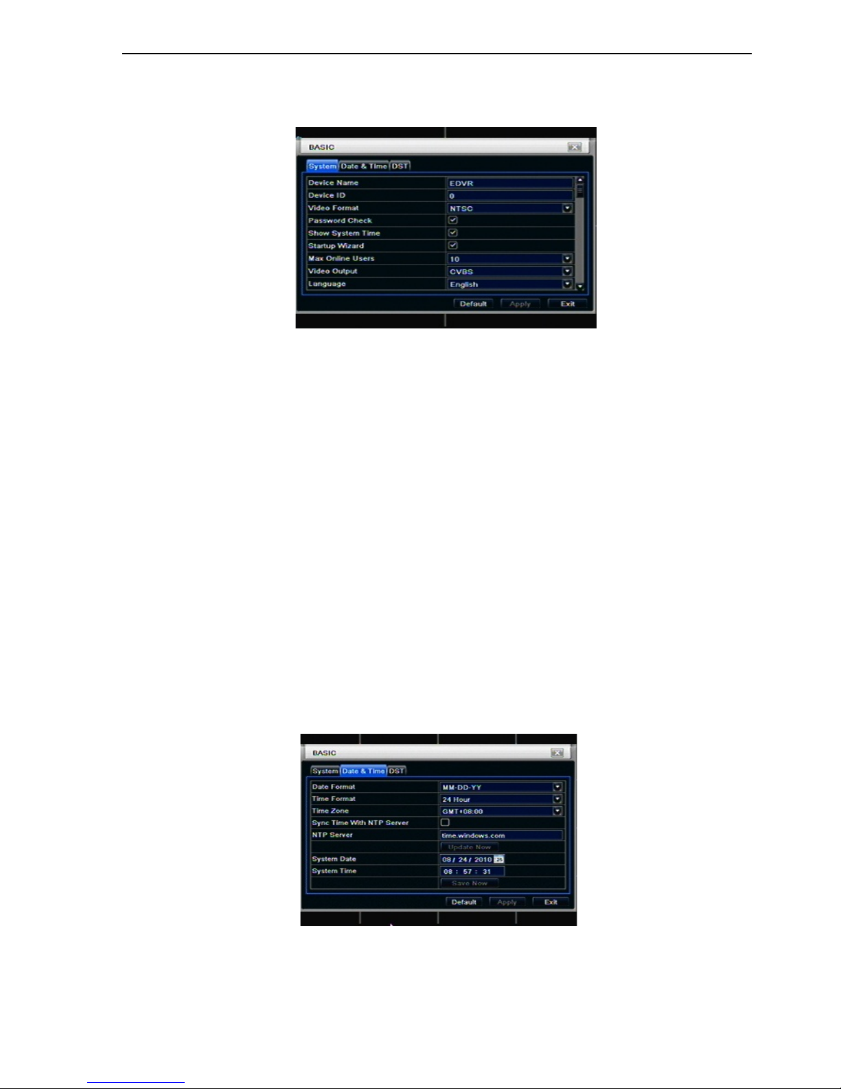
4.1 Basic configuration
Basic configuration includes three sub menus: system、date& time and DST.
4.1.1 System
Step1: enter into system configurationbasic configurationsystem; refer to Fig 4-3:
Fig 4-3 basic configuration-basic
Step2: in this interface user can setup the device name, device ID, video format, max network
users, VGA resolution and language. The definitions for every parameters display as below:
Device name: the name of the device. It ma y display on the c lient end or CMS that help user to
recognize the device remotely.
Video format: two modes: PAL and NTSC. User can select the video format according to that of
camera.
Password check: enable this option, user needs to input user name and password can do
corresponding operations with the relevant right in system configuration.
Show time: display time in live.
Show wizard: tick off th i s item, there will display an opening wizard with time zone and time setup
information
Max network uses: set the max user amount of network connection
VGA resolution: the resolution of live display interface, range from: VGA800*600 、
VGA1024*768、VGA1280*1024and CVBS
Note:When switch between VGA and CVBS will change the menu output mode, please
connect to relevant monitor.
Language: setup the menu language.
Note: after changed the language and video output, the device needs to login again
.
4.1.2 Time & date
Step1: enter into system configurationbasic configurationtime & date; refer to Fig 4-4:
16 CH
Fig 4-4 basic configuration-time & date
Step2: set the date format, time format, time zone in this interface; click off “sync time with NT P
server” to refresh NTP server date; user also can adjust system date manually
Step3: click “default” button to resort default setting; click “apply” button to save the setting; click
“exit” button to exit current interface
.
DV-8_HDRS-04-1U / DV-9_HDRS-08-2U / DV-10_HDRS-16-2U User’s Manual
R201304-V10
13
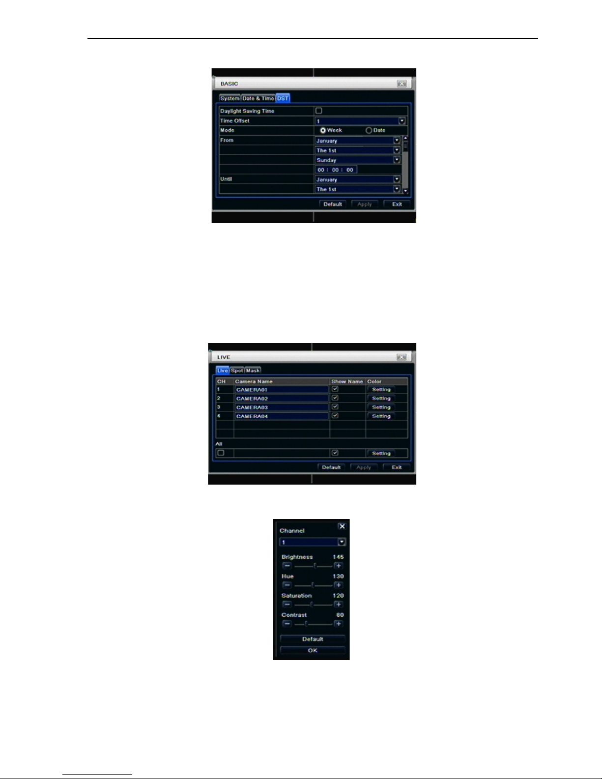
4.1.3 DST
Step1: enter into system configurationbasic configurationDST; refer to Fig 4-5:
Fig 4-5 basic configuration-DST
Step2: in this interface, enable daylight saving time, time offset, mode, start & end month/week/date, etc.
Step3: click “default” button to resort default setting; click “apply” button to save the setting; click “exit” button
to exit current interface.
4.2 Live configuration
Live configuration includes four submenus: live, host monitor, SPOT and mask.
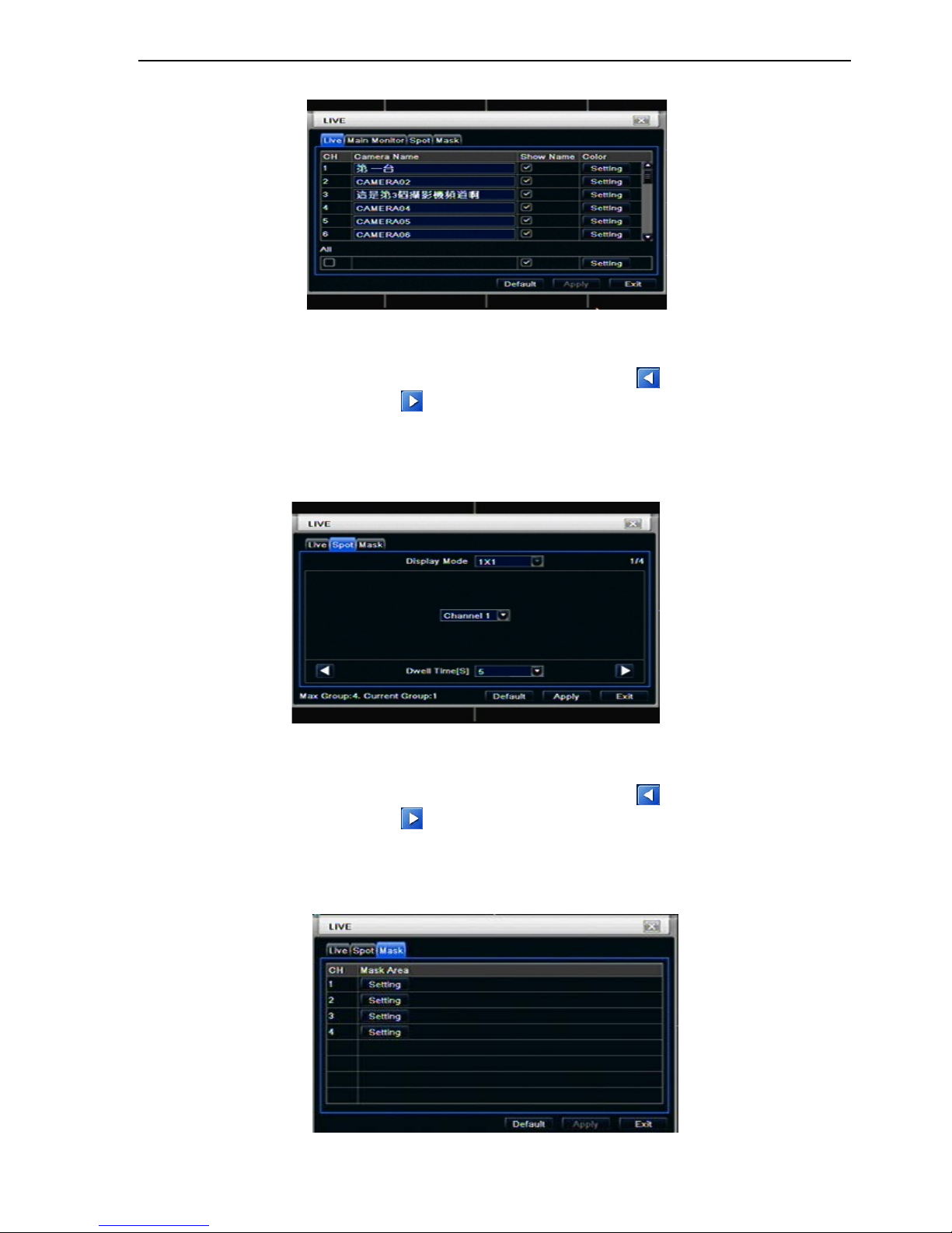
4.2.1 Live
In this interface, user can setup camera name, adjust colors: brightness, hue, saturation and contrast.
Step1: enter into system configurationlive configurationlive; refer to Fig 4-6:
Fig 4-6 live configurationlive
Step2: tick off camera name; click “setting” button, a window will pop-up as Fig 4-7:
Fig 4-7 live-color adjustment
Step3: in this interface, user can adjust brightness, hue, saturation and contrast in live; click “default” button
to resort default setting, click “OK” button to save the setting.
Step4: user can setup all channels with same parameters, tick off “all”, then do relevant setup.
Step5: click “default” button to resort default setting; click “apply” button to save the setting; click “exit” button
to exit current interface.
DV-8_HDRS-04-1U / DV-9_HDRS-08-2U / DV-10_HDRS-16-2U User’s Manual
R201304-V10
14
4.2.2 Main monitor
Step1: enter into system configurationlive configurationhost monitor; refer to Fig 4-8:
Fig 4-8 live configuration-host monitor
Step2: select split mode: 1×1、2×2、2×3、3×3、4×4 and channel
Step3: dwell time: the time interval for a certain dwell picture display switching to next dwell picture display
Step4: selected the split mode, then setup current picture group. Click
button to setup the previous
channel groups of dwell picture, click
button to set the latter channel groups of dwell picture.
Step5: click “default” button to resort default setting; click “apply” button to save the setting; click “exit” button
to exit current interface.
4.2.3 SPOT
Step1: enter into system configurationlive configurationSPOT; refer to Fig 4-9:
Fig 4-9 live configuration-SPOT
Step2: select split mode: 1×1and channel
Step3: dwell time: the time interval for a certain dwell picture display switching to next dwell picture display
Step4: selected the split mode, then setup current picture group. Click
button to setup the previous
channel groups of dwell picture, click
button to set the latter channel groups of dwell picture.
Step5: click “default” button to resort default setting; click “apply” button to save the setting; click “exit” button
to exit current interface
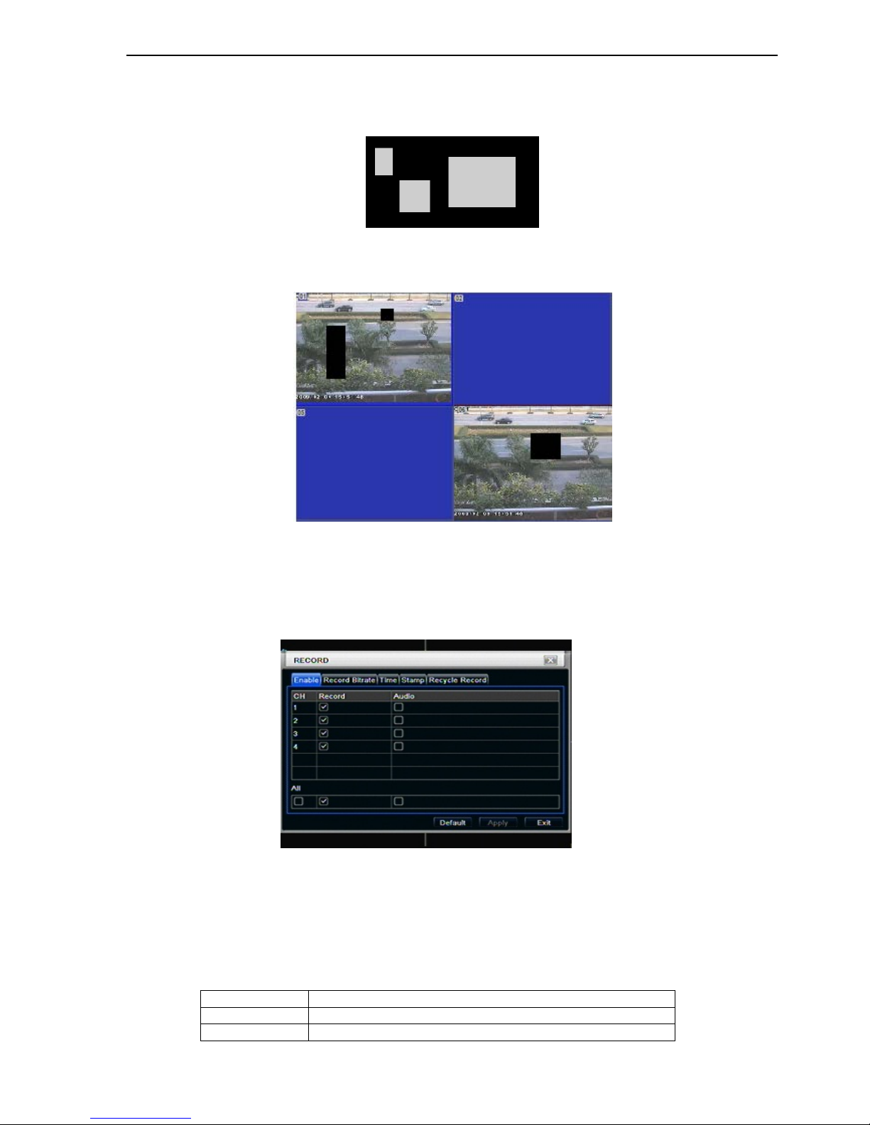
4.2.4 Mask
User can setup private mask area on the live image picture, max three areas.
Fig 4-10 live configuration-mask
DV-8_HDRS-04-1U / DV-9_HDRS-08-2U / DV-10_HDRS-16-2U User’s Manual
R201304-V10
15
Setup mask area: click Setting button, enter into live image to press left mouse and drag mouse to set mask area,
refer to below picture. Click Apply button to save the setting.
Delete mask area: select a certain mask area, click left mouse to delete that mask area, click Apply button to save
the setting.
Setup mask area
Notice: The mask area will not be recorded on DVR. Please use this function carefully.
Live image mask area
4.3 Record configuration
Record configuration includes five sub menus: enable, record bit rate, time, recycle record and stamp.
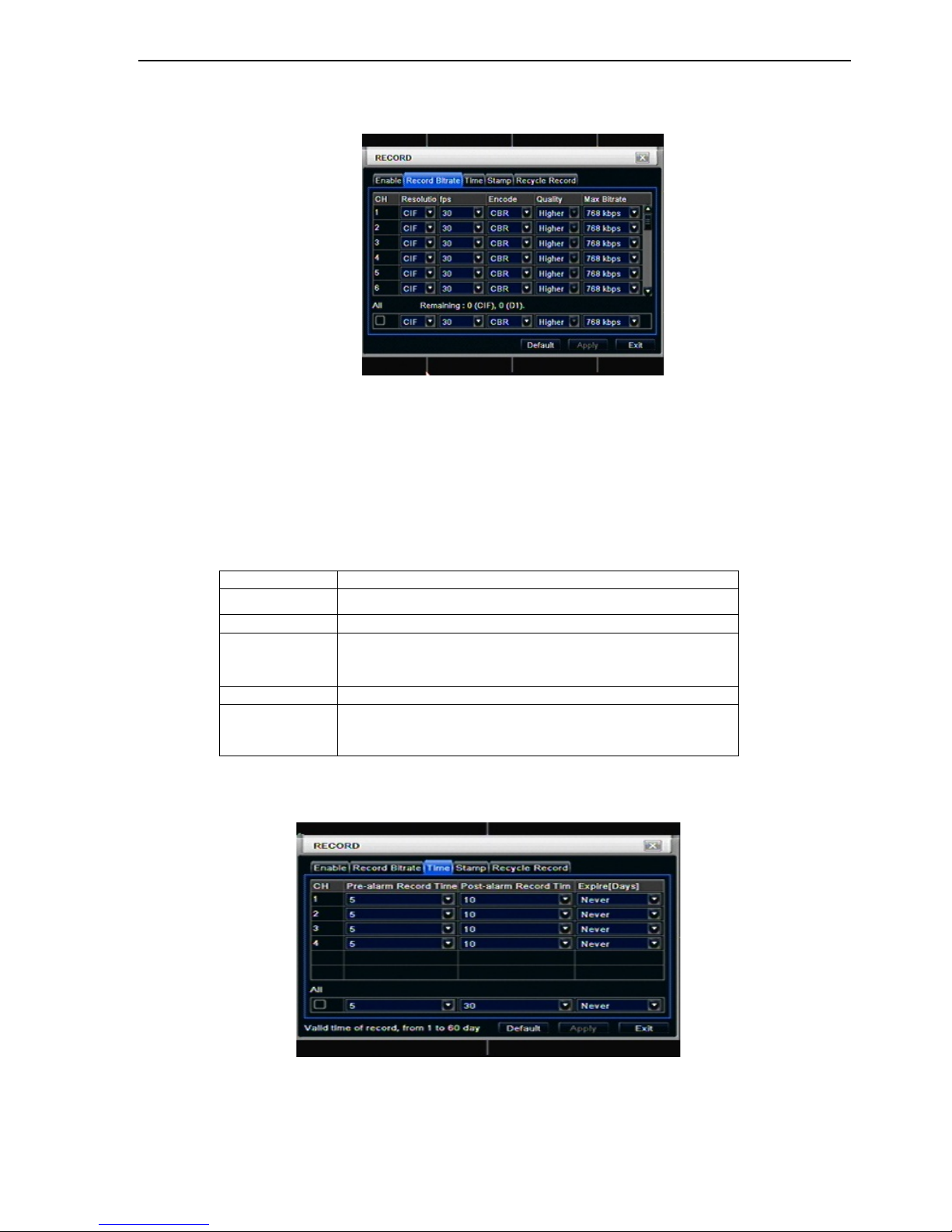
4.3.1 Enable
Step1: enter into system configurationrecord configurationenable; refer to Fig 4-11:
Fig 4-11 record configuration-enable
Step2: tick off record, audio and record time
Step3: user can setup all channels with same parameters, tick off “all”, then to do relevant setup.
Step4: click “default” button to resort default setting; click “apply” button to save the setting; click “exit” button
to exit current interface.
Definitions and descriptions of Record:
Parameter
Meaning
Record
Record switch of every channels
Audio
Enable live record audio
DV-8_HDRS-04-1U / DV-9_HDRS-08-2U / DV-10_HDRS-16-2U User’s Manual
R201304-V10
16
4.3.2 Record stream
Step1: enter into system configurationrecord configurationrecord bit rate; refer to Fig 4-10:
16CH
Fig 4-10 record configuration-record bit rate
Step2: setup rate, resolution, quality, encode and max bit stream
Step3: user can setup all channels with same parameters, tick off “All”, then to do relevant setup.
Step4: click “default” button to resort default setting; click “apply” button to save the setting; click “exit” button
to exit current interface.
Note: if the rate value set is over high the maximum resources of the dev ic e, th e v alue will be adjusted
automatically.
Definitions and descriptions of Record stream:
Parameter
Meaning
Rate
Range from: 1-30(NTSC)1-25(PAL)
Resolution
Support CIF and D1
Quality
The quality of recorded images. The higher the value is, the
clearer the recorded image is. Six option
s: lowest, lower,
low, medium, higher and highest.
Encode
VBR and CBR
Max bit stream
Range f rom: 64 Kbps、128 Kbps、256 Kbps、5 12 Kbps、
768 Kbps、1Mbps、2 Mbps
4.3.3 Time
Step1: enter into system configurationrecord configuration time; refer to Fig 4-12:
Fig 4-12 record configuration-time
Pre-alarm record time: th e record tim e before event happ en i.e. r ecord tim e before m otion detection or sens or
alarm is triggered.
Post-alarm record: set the post recording time after the alarm is finished, five options: 10s, 15s, 20s, 30s and 60s.
 Loading...