

Okina ECO H.264, ECO H.264 DVR User Manual

ECO H.264 DVR
User’s Manual
Version 1.3
00P3L1084ZSEA3

DVR User’s Manual
1
DVR User’s Manual
Caution and Preventive Tips
• Handle with care, do not drop the unit
• Mount the unit in an equipment rack or place it on a solid, stable surface
• Indoor use only, do not place the unit in a humid, dusty, oily, or smoky site
• Do not place it in an area with poor ventilation or in an area close to fire or other sources of
heat. Doing so may damage the unit as well as cause fire or an electric shock
• When cleaning is necessary, shut down the system and unplug the unit from the outlet
before uncovering the top cover. Do not use liquid cleaners or aerosol cleaners. Use only
a damp cloth for cleaning
• Always shut down the system prior connecting or disconnecting accessories, with the
exception of USB devices
This symbol intends to alert the user to the presence of important operating and
maintenance (servicing) instructions in the literature accompanying the
appliance.
This symbol intends to alert the user to the presence of unprotected “Dangerous
Voltage” within the product’s enclosure that may be strong enough to cause a
risk of electric shock.
2

DVR User’s Manual
Important Information
Before proceeding, please read and observe all instructions and warnings in this manual.
Retain this manual with the original bill of sale for future reference and, if necessary, warranty
service. When unpacking your unit, check for missing or damaged items. If any item is missing,
or if damage is evident, DO NOT INSTALL OR OPERATE THIS PRODUCT. Contact your
dealer for assistance.
Rack Mounting
Consult with the supplier or manufacturer of your equipment rack for the proper hardware and
procedure of mounting this product in a safe fashion. Avoid uneven loading or mechanical
instability when rack-mounting units. Make sure that units are installed to get enough airflow
for safe operation. The maximum temperature for rack-mounted units is 40 °C. Check product
label for power supply requirements to assure that no overloading of supply circuits or over
current protection occurs. Mains grounding must be reliable and uncompromised by any
connections.
3

DVR User’s Manual
Table of Content
1. Overview..........................................................................................................................6
2. System Setup..................................................................................................................7
2.1 Position the DVR ...................................................................................................7
2.2 Select Video Format..............................................................................................7
2.3 Connect Devices to the DVR.................................................................................8
2.4 Rear Panel Connections........................................................................................8
3. General System Setup .................................................................................................10
3.1 Front Panel Introduction ......................................................................................10
3.1.1 LED Definition ........................................................................................10
3.1.2 Function Keys ........................................................................................11
3.2 Power Up / Shutdown the DVR ...........................................................................13
3.3 Enter OSD Setup Menu.......................................................................................14
3.4 System Date / Time Setting.................................................................................14
3.4.1 Set Date / Time ......................................................................................15
3.4.2 Daylight Saving Time .............................................................................16
3.5 Record Schedule / Quality Setting ......................................................................16
3.5.1 Schedule Setup......................................................................................17
3.5.2 Preset Record Configuration .................................................................17
3.5.3 Record Event Video Only.......................................................................18
3.5.4 Per Camera Configuration .....................................................................18
3.5.5 ezRecord Setup .....................................................................................19
3.5.6 Circular Recording .................................................................................20
3.5.7 Purge Data .............................................................................................20
4. Basic Operation............................................................................................................21
4.1 View Live / Playback Video .................................................................................21
4.1.1 Viewing Modes.......................................................................................21
4.1.2 Digital Zoom ...........................................................................................22
4.1.3 View Live Cameras ................................................................................22
Freeze Live Image .................................................................................22
4.1.4 View Recorded Video ............................................................................22
Key Usage in Playback ..........................................................................23
Pause Playback and Single Step Forward ............................................23
4.2 Sequence.............................................................................................................24
4.2.1 Sequence with Main Monitor .................................................................24
4.2.2 Sequence with Call Monitor(8CH & 16CH models only) .......................24
4.3 Search Recorded Video ......................................................................................25
4.3.1 Search by Time ......................................................................................25
4.3.2 Search by Event.....................................................................................26
4

DVR User’s Manual
4.4 Video Export ........................................................................................................27
4.4.1 ezBurn Introduction ................................................................................27
4.4.2 Export Normal Video..............................................................................27
4.4.3 Export Event Video ................................................................................28
4.5 Dome Control.......................................................................................................29
4.5.1 Dome Connection ..................................................................................29
4.5.2 Dome Protocol Setup.............................................................................29
4.5.3 RS485 Setup..........................................................................................30
4.5.4 Dome Controlling Keys ..........................................................................30
4.5.5 Setting Preset Points .............................................................................32
4.5.6 Calling Preset Points..............................................................................33
5. Remote Monitoring Software ......................................................................................34
5.1 Remote Monitoring System Requirements..........................................................34
5.2 Installation of Software ........................................................................................35
5.2.1 Change Internet Settings .......................................................................35
5.2.2 Install the Remote Monitoring Software.................................................37
5.2.2.1 Login / Logout...........................................................................38
5.2.2.2 Software Upgrades...................................................................39
5.3 Basic Operation ...................................................................................................39
5.3.1 View Live Video......................................................................................39
5.3.1.1 Select Display Mode.................................................................40
5.3.1.2 Operating Cameras with Dome Control ...................................40
5.3.2 Instant Recording...................................................................................41
5.3.2.1 Record Video Instantly .............................................................41
5.3.2.2 Playback Instant Recorded Video ............................................41
5.3.3 Playback Video ......................................................................................42
5.3.3.1 Playback Remote Video ...........................................................42
5.3.3.2 Playback Local *.drv Files ........................................................43
5.3.3.3 Playback Controls ....................................................................43
5.3.4 Search from Event List...........................................................................44
5.3.5 Take a Snapshot ....................................................................................44
5.3.6 Health Status..........................................................................................44
5.3.7 Remote Monitoring Software Trouble Shooting Guide ..........................45
Appendix A: Technical Specifications.............................................................................46
Appendix B: Recommended HDDs ..................................................................................47
Appendix C: Remote Control............................................................................................48
Appendix D: Setting up a DVR behind a Router.............................................................50
5

DVR User’s Manual
1. Overview
ECO H.264 DVR is an integrated digital video recorder that combines the
features of a time-lapse audio / video recorder, a multiplexer, and a video
server to create a single security solution.
Its outstanding triplex operation enables users to view live video, search and
playback any recorded video by date/time or event, and remotely monitor the
unit via internet on PC, MEANWHILE the recording of the DVR unit is
ongoing simultaneously.
ECO H.264 DVR is enhanced to provide H.264 compression mode. Moreover,
a marvelous implementation is the brand-new experience of Graphical User
Interface (GUI) that optimizes the monitoring controls of the unit.
ECO H.264 DVR is pre-installed with remote viewing and configuration
software, which is a Web-browser plug-in allowing users to view live or
recorded video images, and enables remote configuration. The remote
software is stored in ECO H.264 DVR and deployed over a LAN, WAN or
Internet connection to remote Windows-based computers. This simplifies the
installation and maintenance of the software components so all remote users
are using the same software coming from the unit.
6
DVR User’s Manual
2. System Setup
The notices and introduction on system installation will be described
particularly in this chapter. Please follow the description to operate the unit.
In order to prevent the unit from data loss and system damage that caused by
a sudden power fluctuation, use of an Uninterruptible Power Supply (UPS) is
highly recommended
2.1 Position the DVR
First, note to position / mount the DVR in a proper place and be sure to power
off the unit before making any connections. The placed location should avoid
hindering or blocking the unit from airflow. Enough airflow is needed to
protect the unit from overheating. The maximum allowable temperature of
operating environment is 40°C.
The unit utilizes heat-conducting techniques to transfer internal heat to the
case, especially to the bottom side of the unit.
NOTE: Be sure the rubber feet are not removed, and always leave a
space for air ventilation on the unit’s bottom side.
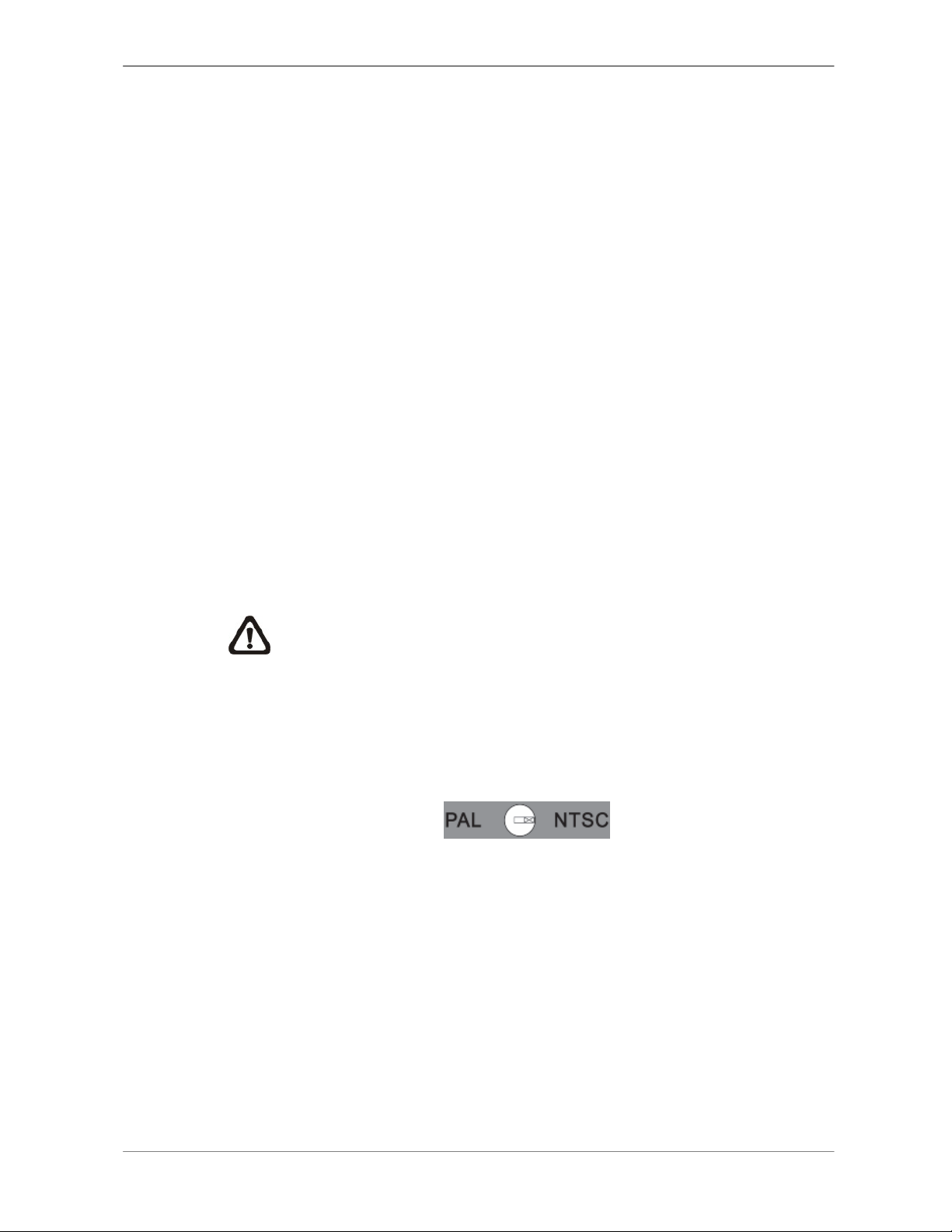
2.2 Select Video Format
The DVR is designed to operate under either NTSC or PAL video formats.
The switch is on the rear panel.
7
DVR User’s Manual
2.3 Connect Devices to the DVR
This section lists some important notices that should be read before making
any connection to the DVR.
Connecting Required Devices
Before power up the unit, cameras and a monitor should be connected to the
unit for basic operation. If needed, connect a call monitor for displaying full
screen video of all installed cameras in sequence.
Connecting Short-term Device
If any short-term devices shall be installed to the DVR as parts of the unit
system, such as USB ThumbDrive® or any USB devices, etc, make sure
those devices are connected only after the unit is powered up. The reason is
because the DVR can recognize the external devices only after the power-up
process is done completely.
2.4 Rear Panel Connections
There are various connectors on the rear panel for the DVR installations. The
following shows the detailed description of each connector.
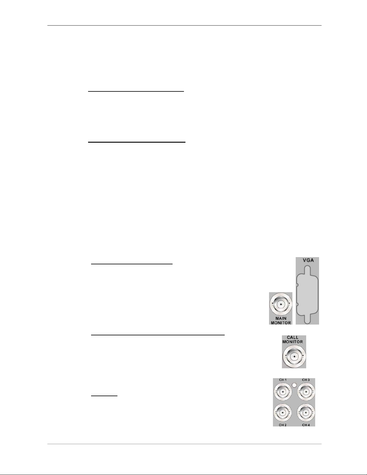
Main Monitor (BNC/ VGA)
BNC and VGA output connectors are offered for
connecting to a main monitor. The main monitor displays
live image and playback recorded video in either
full-screen or split-window format. VGA output connector
is standard feature.
Call Monitor (8CH and 16CH models only)
The call monitor is used to display full screen video of all
installed cameras in sequence. The BNC call monitor
connector allows users to connect the DVR with an
optional call monitor.
Video In
A group of BNC connectors is offered for video input
streams from installed cameras. The number of
connectors is equal to the number of channels.
8
DVR User’s Manual
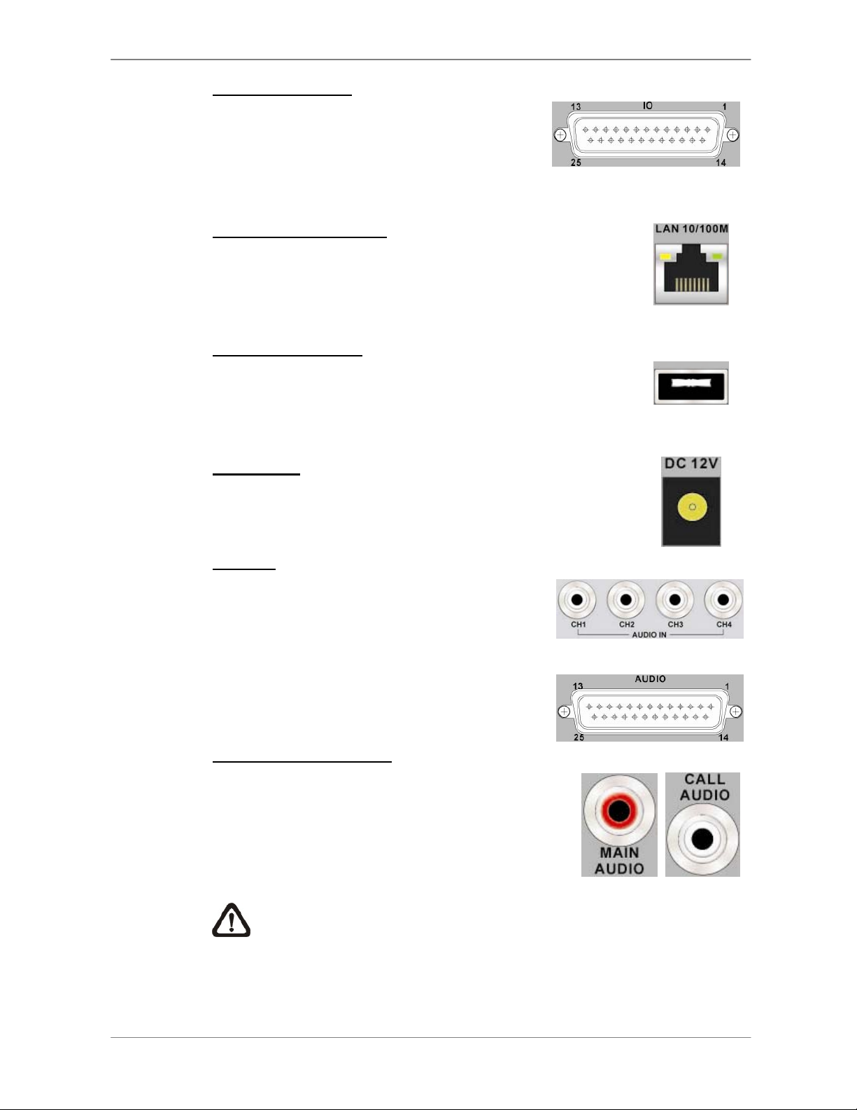
Alarm I/O & RS485
A D-Sub connector is provided to offer users
the flexibility to connect the DVR to Alarm I/O
and RS-485 devices. Refer to Setup Guide
for detailed pin definitions.
LAN Connector (RJ-45)
The DVR is capable of networking. Once the unit is
connected to the LAN network, users can remotely access
the unit through the remote software on a PC.
USB Connector (x1)
There is one USB 2.0 port provided to allow users to
connect external USB devices to the unit, such as a USB
ThumbDrive
®
or a USB mouse.
Power Jack
The DVR has a free voltage DC power connection jack.
Please connect the power adapter shipped with the unit.
Audio In
Audio In connectors are offered for connecting
audio source devices to the unit. 4CH models
offer RCA connectors while 8CH and 16CH
models offer a D-Sub connector.
Audio Out – Main & Call
Main & Call Audio Out RCA connectors are
provided for connecting the DVR to audio output
devices (e.g. amplified speakers). “Main” will
output audio from the main monitor, whereas
“Call” will output audio form the call monitor.
NOTE: Call Audio Out RCA connector is only available for 8CH and
16CH models.
4CH models
8CH & 16CH models
9
DVR User’s Manual
3. General System Setup
Before operating the DVR, some general configuration should be setup first.
The following subsections will introduce function keys on the front panel and
general configuration of the DVR.
The regular displayed OSD information and its displayed positions are shown
as following figure. Title of the channel will be displayed on the top-left corner
of the window, either in full-screen mode or in spilt window mode. The current
operating mode, including Playback mode, Freeze mode and Sequence
mode, will be displayed on the bottom-left corner of the screen. The date/
time information will be display on the bottom-right corner.
Ch1
►*1
2008/05/09 PM04:31:22
3.1 Front Panel Introduction
The front panel controls enable users to control the unit and preset the
programmable functions.
3.1.1 LED Definition
The LEDs on the front panel of the DVR are described as follow.
Power LED
The LED lights up when the correct power is connected to the unit.
REC LED
The LED blinks while the DVR is recording.
Alarm LED
The LED lights up when an alarm is triggered.
Network LED
The LED lights up when the DVR is connected to a network and
blinks when the data is being transferred.
10

DVR User’s Manual
3.1.2 Function Keys
This section describes the functional keys, which are for normal operation, on
the front panel of the DVR.
Please refer to the Setup Guide for the graphical illustration of functional
keys.
CHANNEL
In both Live and Playback modes, press the CHANNEL key to view the
corresponding video in full-screen.
DOME
Press the key to enter dome camera control mode. Please refer to Section
Dome Control
for detailed controlling operation.
MODE
Press repeatedly to select for wanted monitor display format. The available
view modes includes: full-screen, 4-window (2×2), 9-window (3×3) and
16-window (4×4). Refer to Section View Modes
for detailed information.
SEQ (Sequence)
Press to start automatic sequencing of the video coming from the installed
cameras.
MENU
Press this key to enter the OSD setup menu.
COPY
In Playback mode, press COPY to select the start and end time of the export
video. Refer to Section Video Export
for detailed information.
CALL (8CH and 16CH models only)
• In Live mode, press this button to enter Call Monitor Control mode.
• In Dome mode, press CALL in association with ENTER to enter the OSD
setup menu of the dome camera.
11

DVR User’s Manual
PLAY/STOP
Press this key to switch between live image and playback video.
NOTE: According to record setting, part of the latest video cannot
be played back because the video is still saved in the buffer.
FREEZE
• Press FREEZE while viewing live image, the live video will be frozen. The
date / time information shown on the monitor will continue updating. Press
FREEZE again to return to live mode.
• Press FREEZE while playing the recorded video, the playback video will
be paused. Press LEFT / RIGHT to move the recorded video reverse /
forward by single step. Press FREEZE again to continue playing video.
SEARCH
In both Playback and Live mode, users can press SEARCH to display the
Search menu for searching and playing back recorded video by date and
time or events.
ESC
Press to cancel or exit from certain mode or OSD setup menu without
changing the settings made previously.
Direction Keys
• In Zoom mode, these keys function as Direction keys.
• In the OSD menu, the LEFT/ RIGHT keys are used to move the cursor to
previous or next fields. To change the value in the selected field, press
UP/ DOWN.
ENTER / ZOOM
• In OSD menu or selection interface, press this key to make the selection
or save settings.
• In live full screen view mode, press this key to view a 2× zoom image;
press it again to exit zoom mode.
12

DVR User’s Manual
3.2 Power Up / Shutdown the DVR
If the DVR must be shut down for any reason, please use the proper shut
down and power up procedures to avoid damaging the DVR.
To Power Up the Unit
Simply plug in the power adapter that came with the package and the DVR
will start to boot.
The color bar and system checking information will be shown on the monitor
and then disappear when the unit has been completely powered up.
To Restart / Shutdown the Unit
Press MENU and input the administrator password to access the OSD setup
menu. Select <Shutdown> in Main Menu and press ENTER to enter the
Shutdown menu, which displays as follows.
Shutdown
1. Power Off
2. Reboot
Execute
Execute
<Power Off>
Select this item to shut down the unit. Do not remove the power during shut
down until the message “You can safely turn off DVR now!” displays.
<Reboot>
Select this item to reboot the unit. The color bar and system checking
information are displayed on the monitor until the unit is completely restarted.
13
DVR User’s Manual
3.3 Enter OSD Setup Menu
The configuration of the DVR can be customized by entering the intuitive
Graphical User Interface (GUI) OSD setup menu. Collaborating with a USB
mouse, setting up the DVR can be easy as operating on a PC. Press MENU
and enter Administrator or User password to enter the OSD setup menu. The
Password Verification screen displays as follows.
Password Verification
________
Press Channel Keys To Enter Password
(4-8 Digits)
Press ◄ Key To Delete
The default passwords are shown in the following table. The same passwords
are used for entering the remote viewing software.
Administrator Password User Password
1 2 3 4 4 3 2 1
NOTE: It is strongly suggested to change the passwords to prevent
unauthorized access to the unit.
3.4 System Date / Time Setting
Users can set the current date, time and other OSD parameters in Date/Time
menu (under System Setup Menu). The administrator’s privileges are
required for entering the submenu. In OSD setup menu, select <System
Setup> and press ENTER, then select <Date/Time> to access the Date/Time
menu; the menu displays as follows.
Date/Time
1. Date
2. Time
3. Date/Time Display
4. Date Display Mode
5. Time Display Mode
6. Date/Time Order
7. Daylight Saving Time Setup
2008/02/21
PM10:39:26
1 Row
Y/M/D
12 HR
Date First
14
DVR User’s Manual
3.4.1 Set Date / Time
Set Date / Time
Select <Date> / <Time> and press ENTER for adjusting the settings. LEFT /
RIGHT keys are used to move the cursor to previous or next field, ENTER is
for selecting, and UP / DOWN are used to change the value in the selected
field.
NOTE: The new date / time setting applies to record new video. The
date and time of previously recorded video will not be changed.
NOTE: If time settings have to be changed in any case, it is strongly
recommended to format the HDD to avoid database corruption.
Date / Time Display
Users are allowed to set the time OSD displays in 1 or 2 rows. Use the UP /
DOWN keys to change the setting.
Date Display Mode
This function allows users to set the OSD display type of the date. There are
three options to select from: <Y/M/D>, <M/D/Y> or <D/M/Y>. “Y” represents
“Year”, “M” represents “Month” and “D” represents “Day”.
Move to the item and press ENTER, the option starts blinking. Use UP /
DOWN keys to change the setting.
Time Display Mode
Users can set the time format to <12 hour> or <24 hour>. Use the UP /
DOWN keys to change the format.
Date / Time Order
The item is used to set the order of date / time display to <Date First> or
<Time First>. Use UP / DOWN keys to change the setting.
15
 Loading...