

Okina B00PVFKGS0 User Manual

Thank you for purchasing our product.
Please read this user’s manual before
using the product. Change without notice
H.264
Real Ti me HD DVR
User’s Manual

2
CAUTION
Please read this user manual carefully to ensure that you can use the device correctly and safely
We do not warrant all the content is c o rrect. The contents of this manua l are subject to change
without notice
This device should be operated only from the type of power source indicated on the marking label.
The voltage of the power must be verified before using. If not in use for a long time, pull out the plug
from the socket
Do not install this device near any heat sources such as radiators, heat registers, stoves or other
device that produce heat
Do not install this device near water. Clean only with a dry cloth
Do not block any ventilation openings. And ensure well ventilation a round the machine
Do not power off the DVR at normal recording condition! The correct operation to shut off DVR is to
stop recording firstly, and then s el ect “s hut-down” button at the right of t he me nu bar to e xit, and fi nal ly
to cut off the power.
This machine is indoor using equipment. Do not expose the machine in rain or moist environment. In
case any solid or liquid get into the machine’s case, please cut off the power supply immediately, an d
ask for qualified technicians to check the machine before restart
Refer all servicing to qualified service personnel. No any parts repaired by yourself without technical
aid or approval.
This manual is suitable for 4, 8, 16 channel HD digital video recorders.

3
1.1 Main Features
COMPRESSION FORMAT
Standard H.264 compression with low bit rate and better image quality
LIVE SURVEILLANCE
Support VGA /CVBS/HDMI output
Support 4/ 8/ 16 channel SDI video input
Support channel secur i t y b y hid ing li ve display
Display the local record state and basic information
Support USB to make full control
RECORD MEDIA
4/ 8 /16 channel HD DVR supports 8 SATA HDD or 4 SATA HDD if a DVD-RW writer is installed inside
BACKUP
Support USB 2.0 devices to backup
Support saving recorded files with AVI standard format to a remote computer through internet
RECORD & PLAYBACK
Record modes: Manual, Schedule, Motion detection and Sensor alarm recording
Supports recycle after HDD full
Resolution, frame rate and picture quality are adjustable
128MB for every video file packaging
4/8/16 audio channels available
Three record search mode: time search, event search and image search
Support 1/4 (1080P) screen playback simultaneously
Support deleting and locking the recorded files one by one
Support remote playback in Network Client through LAN or internet
ALARM
4 channel alarm output and 4/8/16 channel alarm input available
Support schedule for motion detection and sensor alarm
Support pre-recording and post recording
Support linked channels recording once motion or alarm triggered on certain channel
Support linked PTZ preset, auto cruise and track of the corresponding channel
PTZ CONTROL
Support various PTZ protocols
Support 128 PTZ presets and 8 auto cruise tracks
Support remote PTZ control through internet
SECURITY
Customize user right: lo g search, s ystem setup, t wo way audio, fi le managem ent, disk m anagement, rem ote
login, live view, manual record, playback, PTZ control and remote live view
Support 1 administrator an d 63 user s.
Support event log recording and checking, events unlimited
NETWORK
Support TCP/IP, DHCP, PPPOE, DDNS protocol
Support IE browser to do remote view
Support setup client connection amount
Support dual stream. Network stream is adjustable independently to fit the network bandwidth and
environment.
Support picture snap and color adjustment in remote live
Support remote time and event search, and channel playback with picture snap
Support remote PTZ control with preset and auto cruise
Support remote full menu setup, changing all the DVR parameters remotely
Support mobile surveillance by Smartphone, Iphone, Android Smartphone, 3G network available
Support CMS to manage multi devices on internet
4
Front Panel Instructions
Notice: The pictures are only for reference; please make the object as the standard.
The Front Panel interface for 4/8/16 channel HD DVR is shown as below:
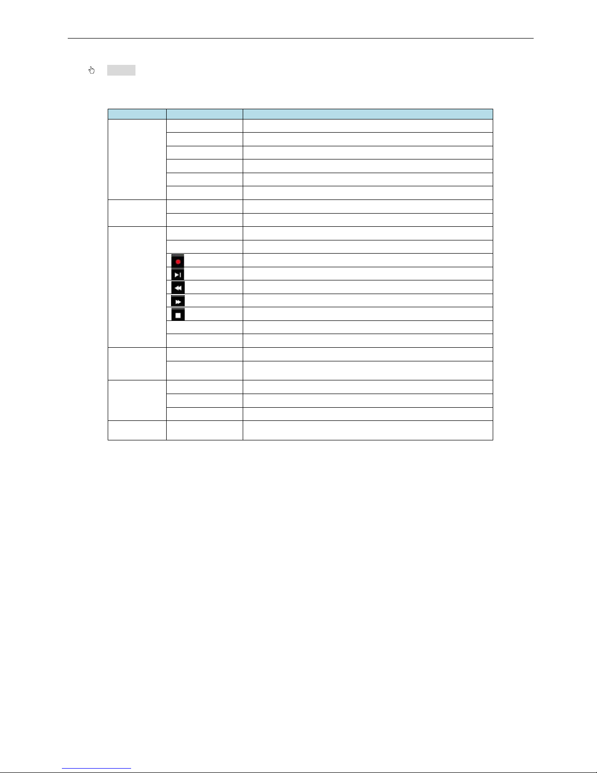
Type
Name
Description
Work state
indicator
REC When recording, the light is blue
HDD When HDD is writing and reading , the light is blue
Backup When backup files and data, the light is blue
Net
When access to network , the light is blue
Play When playing video, the light is blue
Power Power indicator, when connection , the light is blue
Compound
button
P.T.Z./ - 1. Enter PTZ mode in live 2. Decrease the value in setup
AUDIO/+ 1. Control voice 2. Increase the value in setup
Function
button
MENU Enter menu in liv e
INFO
Check recording data
Record manually
Play/Pause
Rewind
Fast forward
Exit/ESC
BACKUP Enter backup mode in live
SEARCH Enter search mode
Digital button
1-9 Input number 1-9 or choose camera
0/10+
Input number0, 10 and the above number together with other
digital keys
Input button
Direction button
Change direction to select items
Multi-screen Change screen display mode like1/4/9/16 cha nnel
Enter button Confirm selection
USB USB port
To connect external USB devices like USB flash, USB HDD for
backup or update firmware;
5
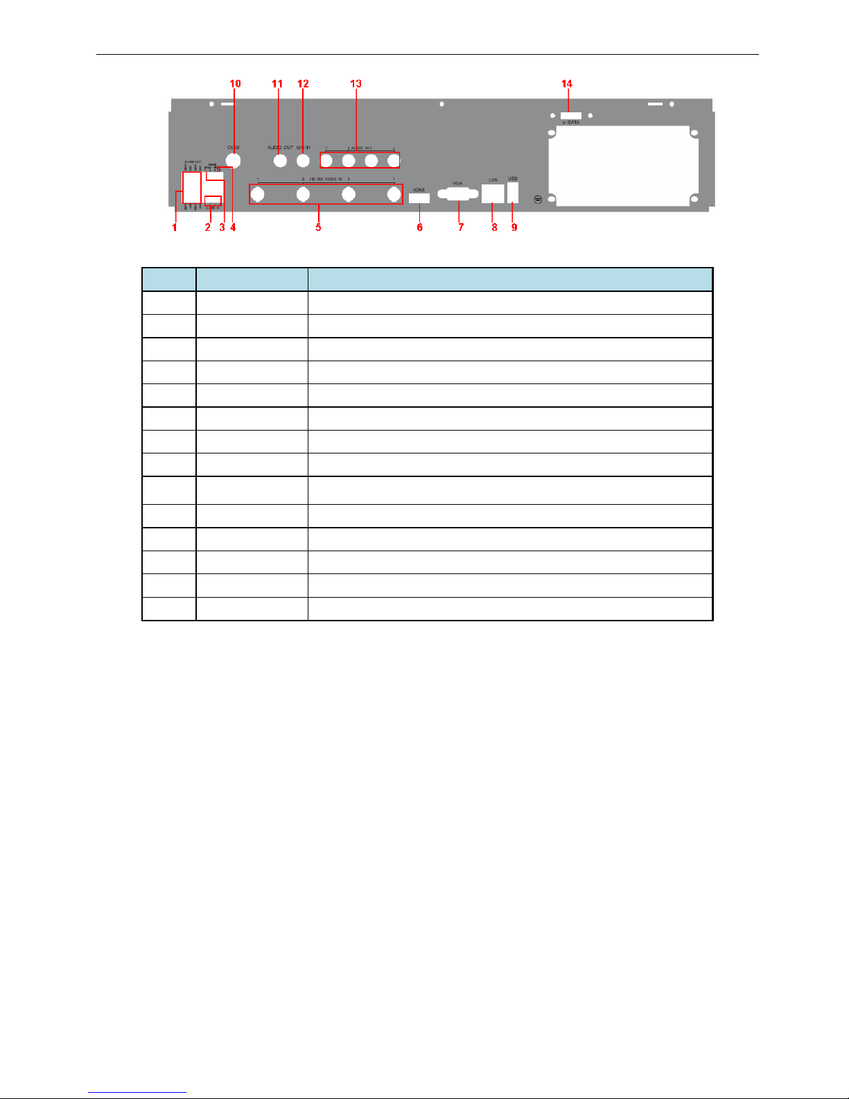
Rear Panel Instructions
Fig 2-3 Rear Panel for 4-CH
Item Name Description
1 Alarm out Relay Output. Connect to external alarm.
2 Alarm in Connect to external sensor
3 P/Z Connect to speed dome. Y is TX+, Z is TX-.
4 K/B Connect to keyboard. A is TX+, B is TX-.
5 HD SD Video in HD SDI video signal inputs.
6 HDMI port Connect to high-definition display device
7 VGA port VGA output, connect to monitor
8 LAN Network port
9 USB port
To connect external USB devices like USB flash drive, USB HDD for
backup or updating firmware.
10 CVBS CVBS output
11 Audio out Audio output, connect to the sound box
12 MIC in Talk. Connect to microphone
13 Audio in Audio input
14 E-SATA Connect to HDD for backup.
6
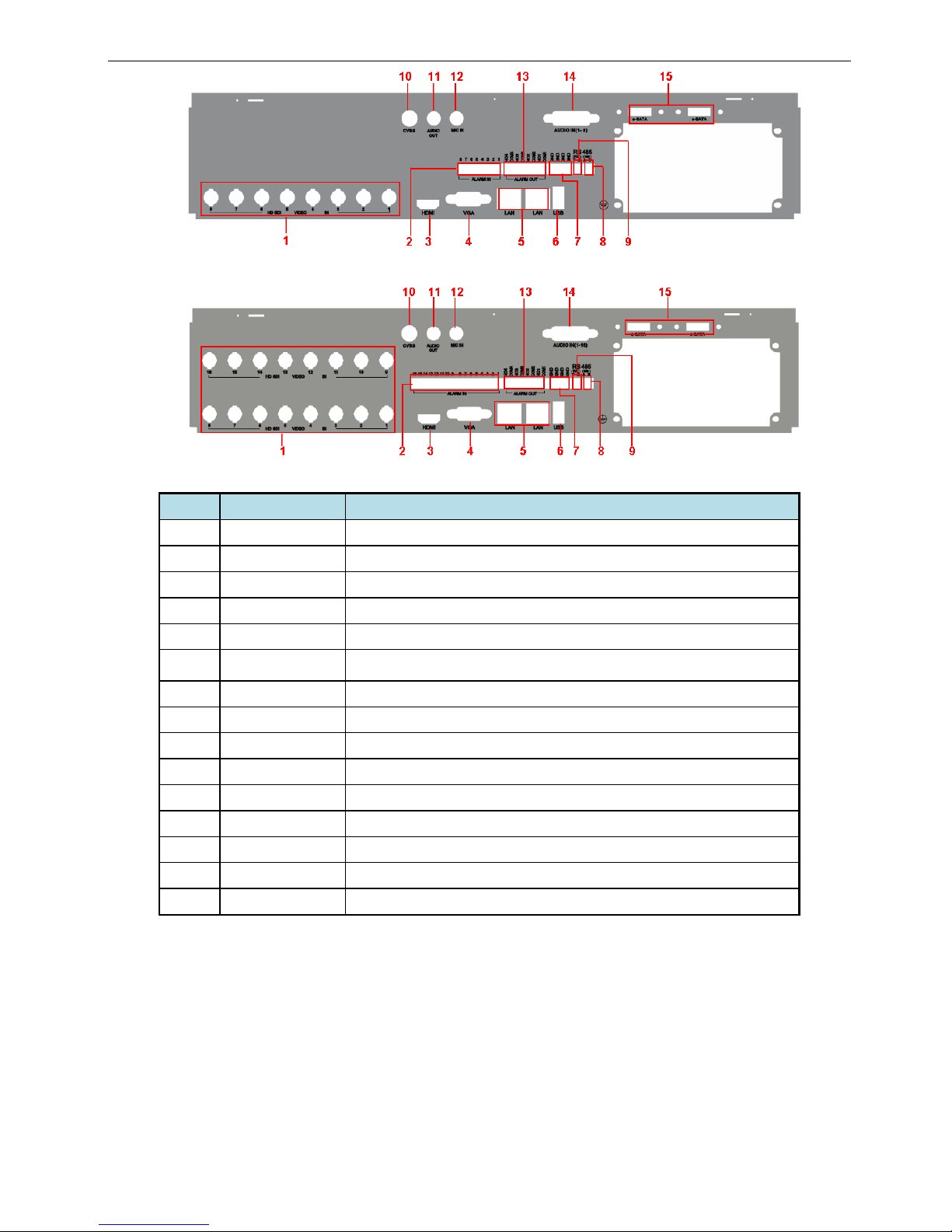
Fig 2-4 Rear Panel for 8-CH
Fig 2-5 Rear Panel for 16-CH
Item Name Description
1 HD SD Video in HD SDI video signal inputs.
2 Alarm in Alarm Inputs for connecting sensors
3 HDMI port Connect to high-definition display device
4 VGA port VGA output, connect to monitor
5 LAN Network port
6 USB port
To connect external USB devices like USB flash drive, USB HDD for
backup or updating firmware.
7 GND Grounding
8 K/B Connect to keyboard. A is TX+, B is TX-.
9 P/Z Connect to speed dome. Y is TX+, Z is TX-.
10 CVBS CVBS output
11 Audio out Audio output, connect to the sound box
12 MIC in Talk. Connect to microphone
13 Alarm out Relay Output. Connect to external alarm.
14 Audio in Audio input
15 E-SATA Connect to HDD for backup.
7
1.2
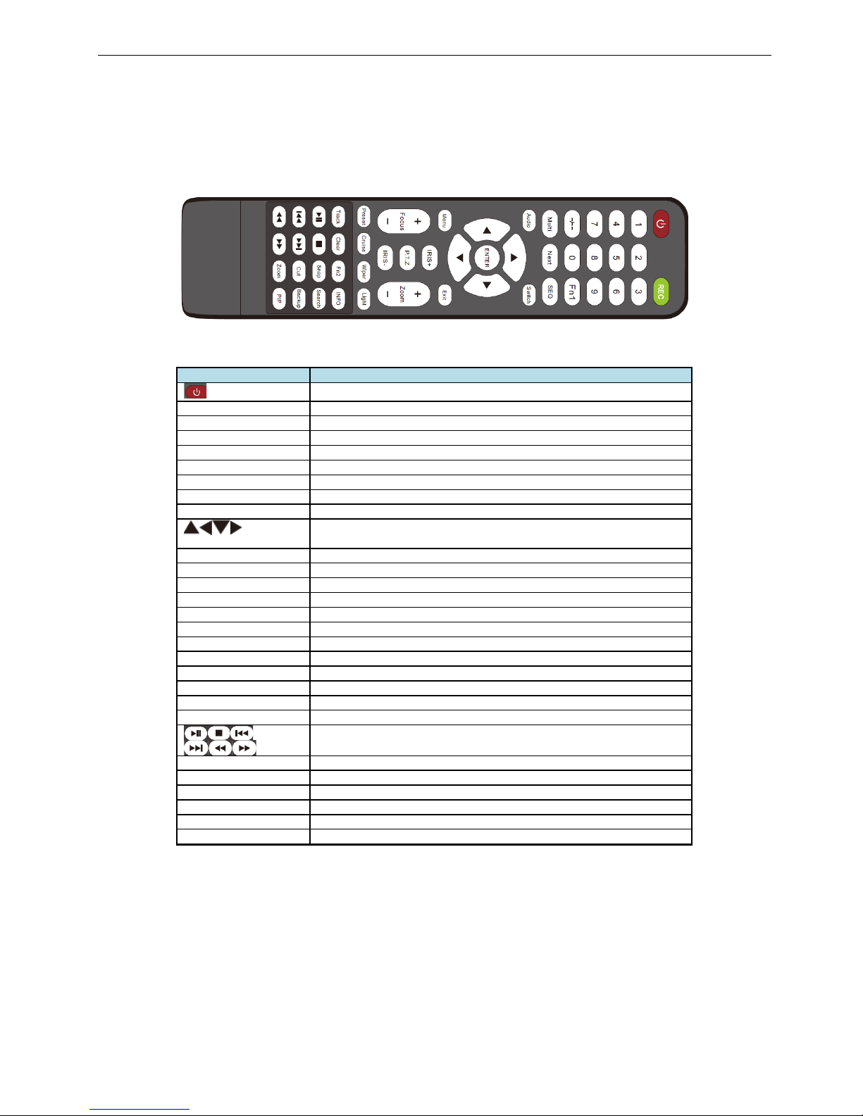
Remote Controller (Optional)
It uses two AAA size batteries.
• Open the battery cover of the Remote Controller.
• Place batteries. Please take care of the polarity (+ and -).
• Replace the battery cover.
Fig 2-6 Remote Controller
Button
Function
Power Button
Switch off—to stop DVR. Use it before turning off the power
Record Button
To record manually
-/-- /0-9 Digital Button
Input number or choose camera
Fn1 Button
Unavailable temporarily
Multi Button
To choose multi screen display mode
Next Button
To switch the live image
SEQ
To enter into auto dwell mode
Audio
To enable audio output in live mode
Switch
To switch the output between BNC and VGA
Direction button
To move cursor in setup or pan/title PTZ
Enter Button
To confirm the choice or setup
Menu Button
To enter into menu
Exit Button
To exit the current interface
Focus/IRIS/Zoom/PTZ
To control PTZ camera. Move camera/zoom/IRIS/Focus
Preset Button
To enter into preset setting in PT Z mode
Cruise Button
To enter into cruise setting in PTZ mode
Track Button
To enter into track setting in PTZ mode
Wiper Button
To enable wiper function in PTZ mode
Light Button
To enable light function in PTZ mode
Clear Button
To return to the previous interface
Fn2 Button
Unavailable temporarily
Info Button
Get information about DVR like firmware version, HDD information
To control playback. Play/Pause/Stop/Previous Section/Next
Section/Rewind/Fast Forward
Snap Button
To take snapshots manually
Search Button
To enter into search mode
Cut Button
To set the start/end time for backup in playback mode
Backup Button
To enter into backup mode
Zoom Button
To zoom in the images
PIP Button
To enter into picture in picture setting mod e
8
1.3 Control with Mouse
1.3.1 Connect Mouse
It supports USB mouse through the port on the rear panel, please refer to Fig 2.11 Remote Controller.
Notice: If mouse is not detected or doesn't work, check below steps:
1. Make sure the mouse is connected to the USB mouse port not the USB port
2. try another mouse
1.3.2 System operation by mouse
The structure of the main menu is shown in Fig 2.11 Remote Controller.
In live:
Double-click left button on one camera to be full screen disp lay. Double-click again to return to the previous
screen display.
Click right button to show the control bar at the bottom of the screen as Fig 2.11 Remote Controller. Here are all
control and setup. Click right mouse again to hide the control bar.
In setup:
Click left button to enter. Click right button to cancel setup, or return to the previous.
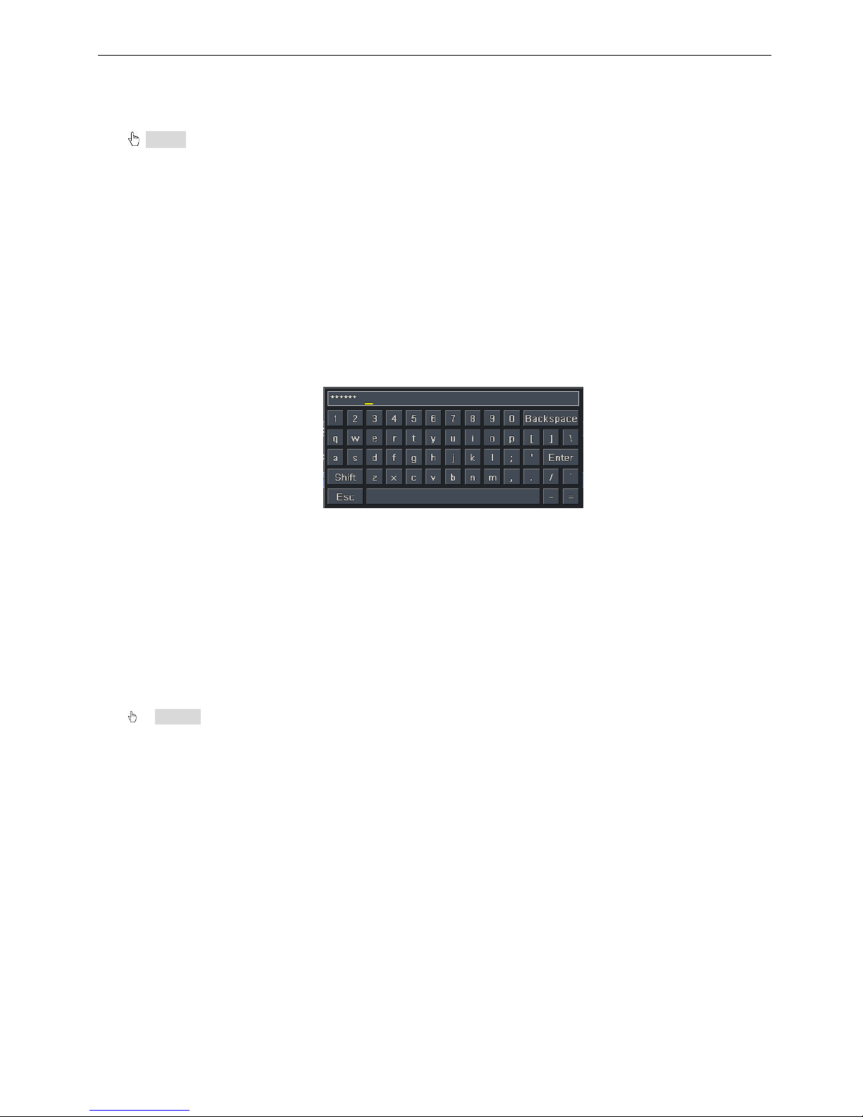
If want to input the value, move cursor to the blank and click. An input window will appear as Fig2.12. It
supports digitals, letters and symbols input.
Fig 2.12 Digital Numbers and Letters Input Window
Users can change some v alue by the wheel, such as tim e. Move cursor onto the value, and ro ll the wheel
when the value blinks.
It supports mouse drag. I.e. Set motion detection area: click customized, hold left button and drag to set motion
detection area. Set schedule: hold left button and drag to set schedule time
In playback:
Click left button to choose the options. Click right button to return to live mode.
In backup:
Click left button to choose the options. Click right button to return to previous picture.
In PTZ control:
Click left button to choose the buttons to control the PTZ. Click right button to return to live.
Notice: Mouse is the default tool in all the operation below unless Exceptional indication.
9
2 Basic Function Instruction
2.1 Power On/Off
Before you power on the unit, please make sure all the connection is good.
2.1.1 Power on
Step1: connect with the source power; switch on the power button near the power port in the rear panel
Step2: the device will start to boot, and the power in dic ator will become blue
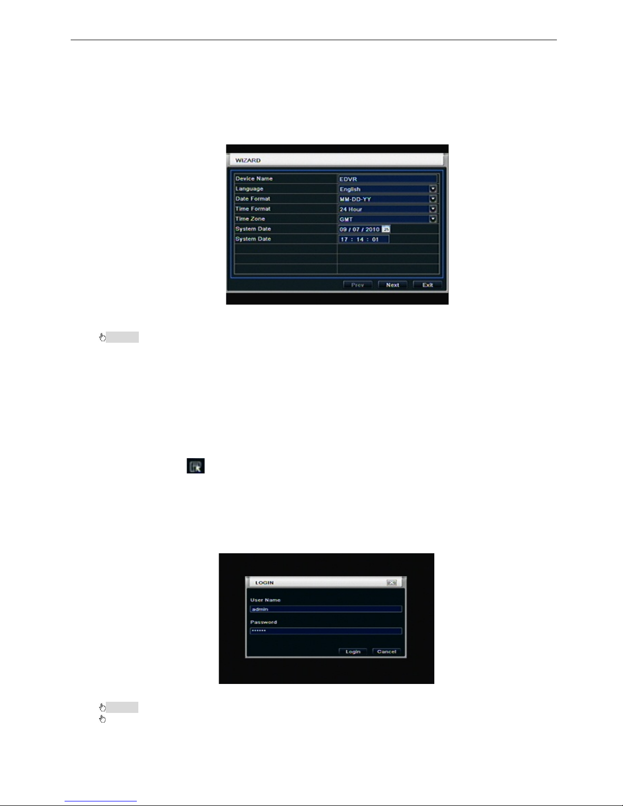
Step3: before start, a WIZARD dialogue box will pop-out (refer to below picture) and show some information
about time zone and time setup, IP information, record quick setup and HDD information page.
After the device powers on , if there is no menu or onl y has live image display, user can long press ES C
button to switch.
Notice: this serial device can only display menu on VGA monitor or BNC monitor at one time, if there is
live image display without menu display, please check up whether other device has menu display firstly, or
long press ESC key to wait for login dialog box to appear.
2.1.2 Power off
User can power off the device by using remote controller, keyboard and mouse.
By remote controller:
Step1: press Power button, the shut down window will appear, click OK, the unit will power off after a while.
Step2: disconnect the power
By keyboard and mouse:
Step1: enter into Menu, then select “System Shut Down” icon, the S hut do wn windo w wil l appear
Step2: click OK, the unit will power off after a while.
Step3: disconnect the power
2.2 Login
User can login and logout the DVR system. User cannot do any other operations except changing the
multi-screen displa y once logou t.
Fig 3-1 Login
Notice: the default user name and password is “admin” and 123456”
The concrete operation steps for change password, add or delete user please refer to Fig 3.7 User
management configuration for more details.
10
2.3 Live preview
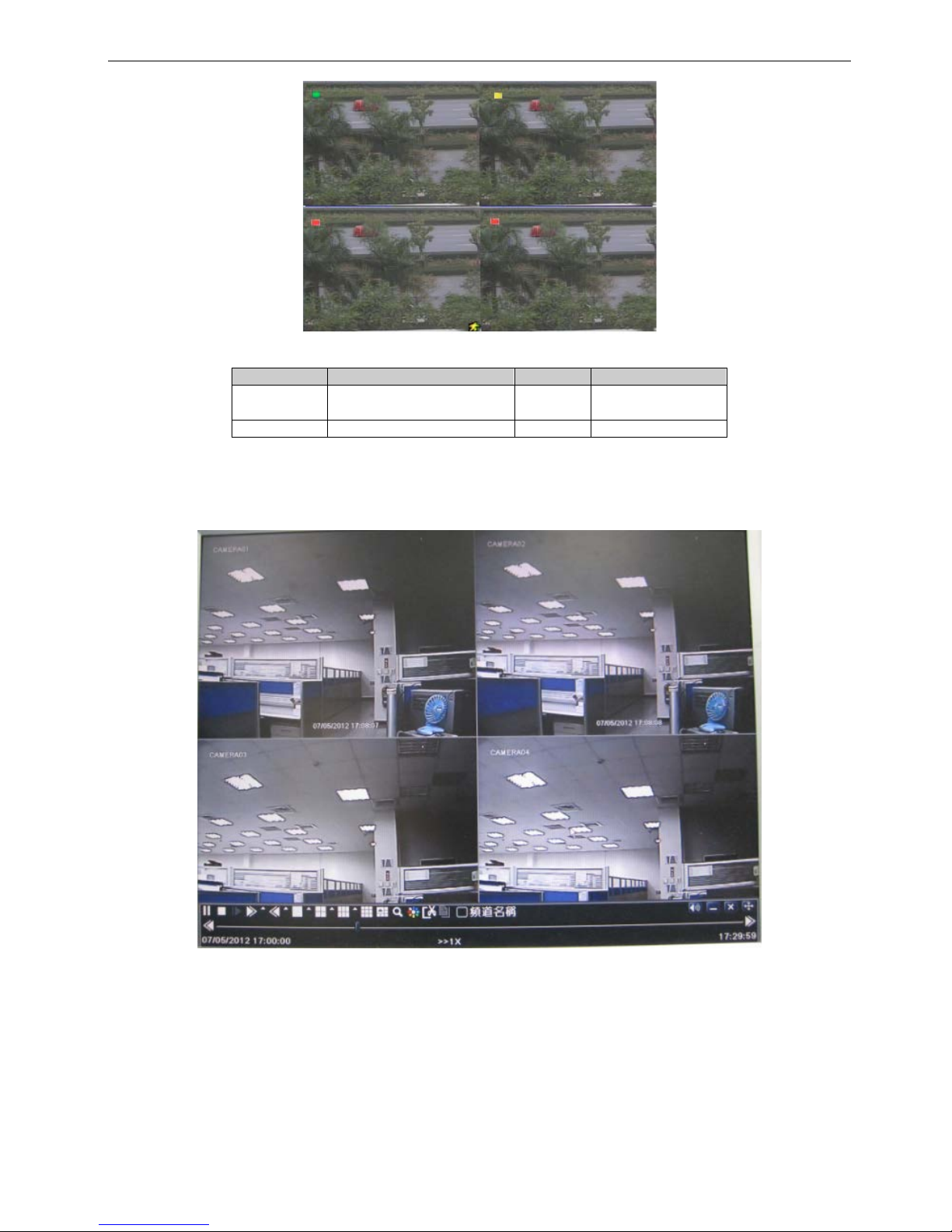
Fig 3-2 live pre view interface
The explanation of symbol in the live preview interface:
symbol
meaning
symbol
meaning
Green Manual record Red
Alarm in trigger
record
Yellow
Motion detection record
Blue
Schedule record
2.3.1 Live playback
Click Play butt on to playback the recorde d video. Refer to Figure3-3. User can do concrete operation by
click the buttons on screen.
11
Fig 3-3 live playback
3 Main menu setup guide
Click right mous e or pr es s E SC button on the fr ont panel, t he control bar will display on the screen, r ef er to
Fig 4-1:
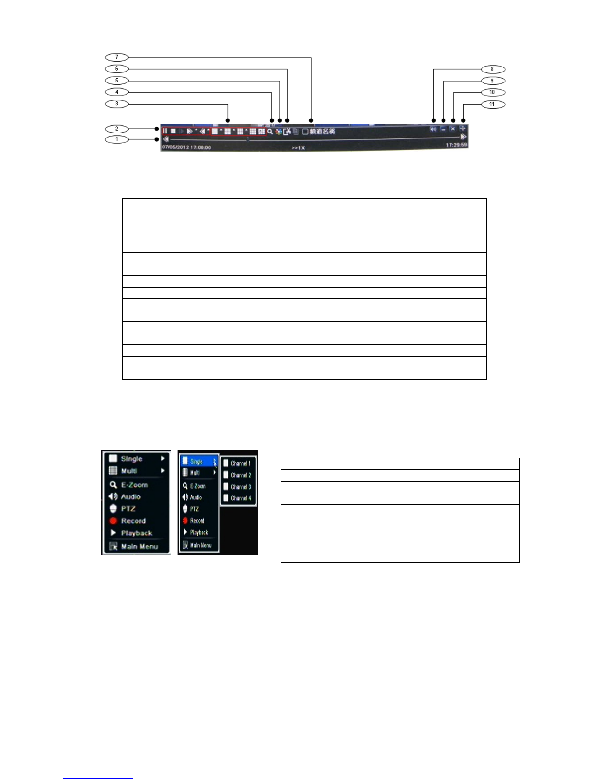
1
Single
Full channel
2
Multi
4ch:1/4, 8ch:1/4/9, 16ch:1/4/9/16
3
E-Zoom
Live/playback digital zoomx2
4
Audio
Audio channel setup and volume
5
PTZ
Into PTZ control mode
6
Record
Manual record
7
Playback
Playback the nearest file
8
Main Menu
Into main OSD
9
Dwell
Channel sequence(only 16CH)
Fig 4-1 main menu toolbar
Item Function Description
1
Playback process bar
Last/next segment of record and time process
2 Playback basic function
Play/ Pause / Stop / frame forward / fast forward
/ fast rewind
3 Display mode
4ch:1/ 4, 8ch:1/ 4/ 6/ 9/ 1+5/ 1+7,
16ch:1/ 4/ 6/ 9/ 16/ 1+5/ 1+7/ 1+12
4
Zoom
Screen digital zoom x2
5
Color
Setup picture color
6 Cut
Enable to select a spec if ic part of the video and
back it up on usb drive
7
Camera name
Enable or disable camera name display
8
Volume
Volume mute on/off
9
Reduce
Hide playback tool bar
10
Exit playback mode
11 Move the playback bar in the screen
Full channel switch, camera 1 ~ 4 or camera 1 ~ 8, camera 1 ~ 16
①
②
③
④
⑤
⑥
⑦
⑧
12
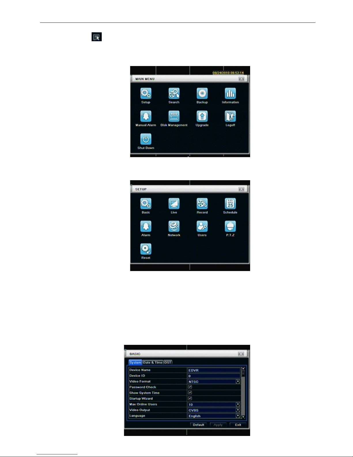
Click Menu button, the interfac e will pop-up as Fig 4-2; pr ess MENU button on the f ront panel or
operate with remote controller also can display the main menu.
Main OSD
Fig 4-2 system setup
3.1 Basic configuration
Basic configuration includes three sub menus: system、date& time and DST.
3.1.1 System
Step1: enter into system configurationbasic configurationsystem; refer to Fig 4-3:
13
Fig 4-3 basic configuration-basic
Step2: in this interface user can setup the d evice name, de vice ID, video f ormat, max networ k users, VGA
resolution and language. The definitions for every parameters display as below:
Device name: the nam e of the devic e. It m a y displa y on t he c lient en d or CMS that help user t o rec ogni ze
the device remotely.
Video format: two modes: PAL and NTSC. User can select the video format according to that of camera.
Password check: enab le this option, user needs to input us er name and passw ord can do corresponding
operations with the relevant right in system configuration.
Show time: display time in live.
Show wizard: tick off this item, there will display an opening wizard with time zone and time setup
information
Max network uses: set the max user amount of network connection
VGA resolution: the resolution of live display interface, range from: VGA800*600、 VGA1024*768、
VGA1280*1024,CVBS and HDMI
Note:When switch between VGA, CVBS and HDMI will change the menu output mode, please
connect to relevant monitor.
Language: setup the menu language.
Note: after changed the language and video output, the device needs to login again.
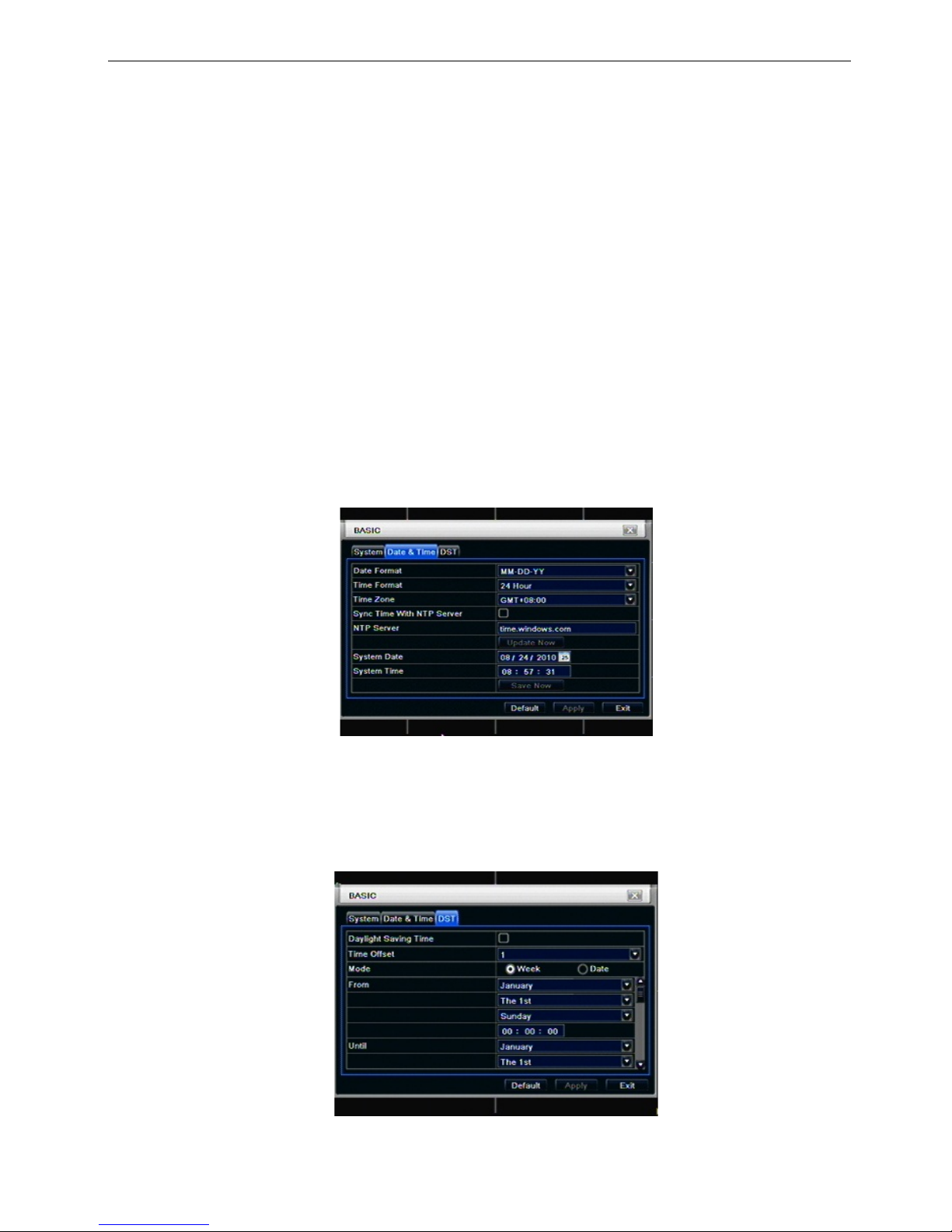
3.1.2 Time & date
Step1: enter into system configurationbasic configurationtime & date; refer to Fig 4-4:
8 CH
Fig 4-4 basic configuration-time & date
Step2: set the da te for mat, ti me format, time zone in this interface; click off “sync time with NTP server” to refresh NTP server date; user
also can adjust system date manually
Step3: click “default” button to resort default setting; click “apply” button to save the setting; click “exit” button to exit current interface.
3.1.3 DST
Step1: enter into system configurationbasic configurationDST; refer to Fig 4-5:
Fig 4-5 basic configuration-DST
Step2: in this interface, enable daylight saving time, time offset, mode, start & end month/week/date, etc.
14
Step3: click “default” button to resort default setting; click “apply” button to save the setting; click “exit” button
to exit current interface.
3.2 Live configuration
Live configuration includes four submenus: live, host monitor, SPOT and mask.
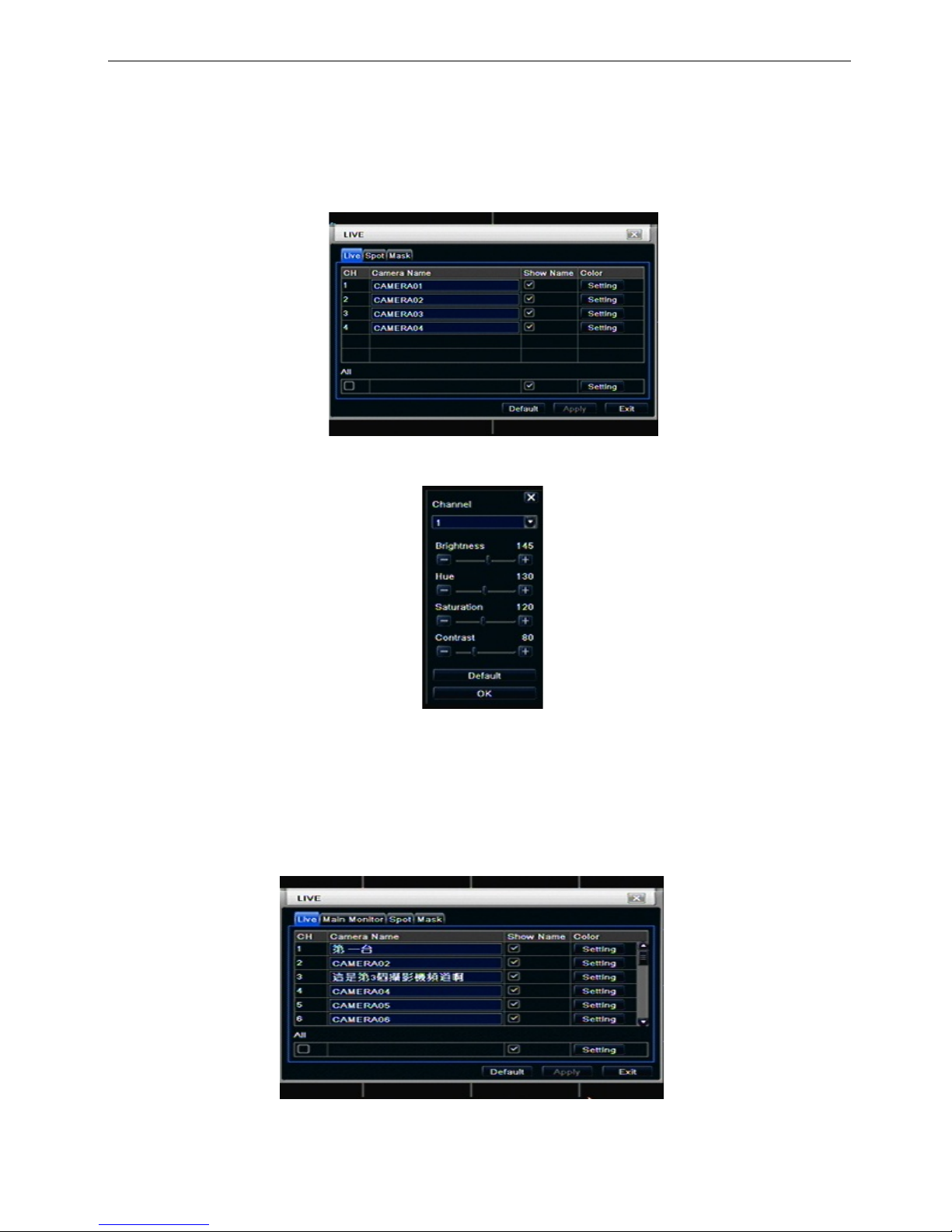
3.2.1 Live
In this interface, user can setup camera name, adjust colors: brightness, hue, saturation and contrast.
Step1: enter into system configurationlive configurationlive; refer to Fig 4-6:
Fig 4-6 live configurationlive
Step2: tick off camera name; click “setting” button , a window will pop-up as Fig 4-7:
Fig 4-7 live-color adjustment
Step3: in this interface, user can adjust brightness, hue, saturation and contrast in live; click “default” button
to resort default setting, click “OK” button to save the setting.
Step4: user can setup all channels with same parameters, tick off “all”, then do relevant setup.
Step5: click “default” button to resort default setting; click “apply” button to save the setting; click “exit” button
to exit current interface.
3.2.2 Main monitor
Step1: enter into system configurationlive configurationhost monitor; refer to Fig 4-8:
Fig 4-8 live configuration-host monitor
15
Step2: select split mode: 1×1、2×2、2×3、3×3、4×4 and channel
Step3: dwell time: the time interval for a certain dwell picture display switching to next dwell picture display
Step4: selected the split mode, then setup current picture group. Click
button to setup the previous
channel groups of dwell picture, click
button to set the latter channel groups of dwell picture.
Step5: click “default” button to resort default setting; click “apply” button to save the setting; click “exit” button
to exit current interface.
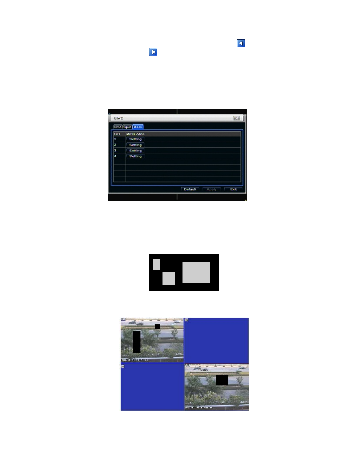
3.2.3 Mask
User can setup private mask area on the live image picture, max threes areas.
Fig 4-10 live configuration-mask
Setup mask area: click Setting butt on, enter into liv e im age to pres s left mouse and dr ag m ouse to set mask
area, refer to below picture. Click Apply button to save the setting.
Delete mask area: select a c er tain m ask ar ea, clic k left mous e to del ete t hat mask area, click Apply button to
save the setting.
Setup mask area
Notice: The mask area will not be recorded on DVR. Please use this function carefully.
Live image mask area
16
3.3 Record configuration
Record configuration includes five sub menus: enable, record bit rate, time, recycle record and stamp.
3.3.1 Enable
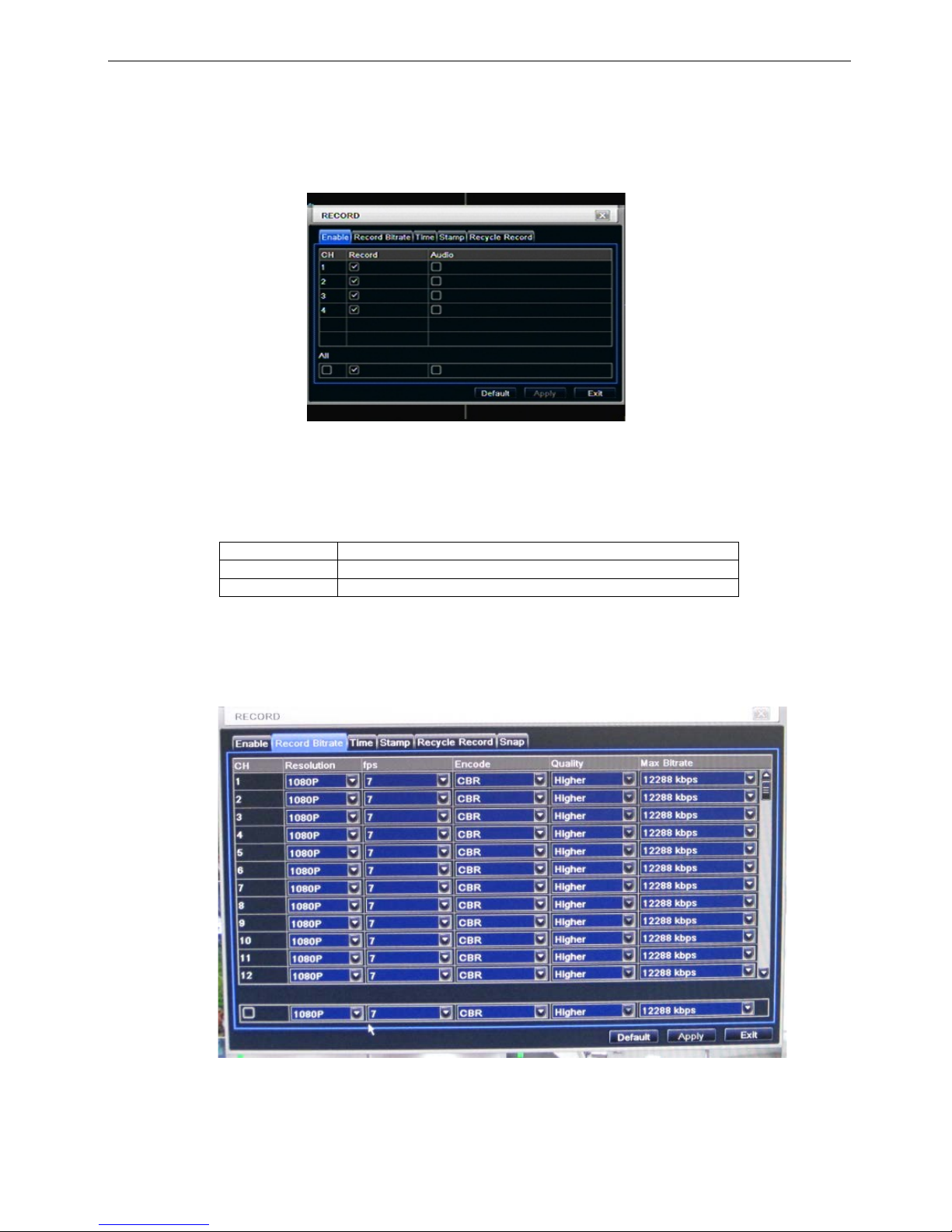
Step1: enter into system configurationrecord configurationenable; refer to Fig 4-11:
Fig 4-11 record configuration-enable
Step2: tick off record, audio and record time
Step3: user can setup all channels with same parameters, tick off “all”, then to do relevant setup.
Step4: click “default” button to resort default setting; click “apply” button to save the setting; click “exit” button
to exit current interface.
Definitions and descriptions of Re cord:
Parameter
Meaning
Record
Record switch of every channels
Audio
Enable live record audio
3.3.2 Record stre am
Step1: enter into system configurationrecord configurationrecord bit rate
Step2: setup rate, resolution, quality, encode and max bit stream
Step3: user can setup all channels with same parameters, tick off “All”, then to do relevant setup.
Step4: click “default” button to resort default setting; click “apply” button to save the setting; click “exit” button
to exit current interface.
17
Note: if the rate value set is over high the maximum resources of the device, the value will be
adjusted automatically.
Definitions and descriptions of Record stream:
Parameter
Meaning
Resolution
Support 1080P,
FPS
4/8/16 CH HD DVR 1080P@30FPS(25FPS)
Quality
The quality of recorded images. The higher the value is, the
clearer the recorded image is. Six options: lowest, lower,
low, medium, higher and highest.
Encode
VBR and CBR
Max bit stream
Range from 1536kbps~12288kbps
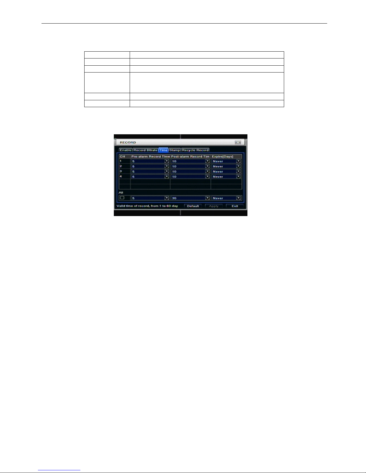
3.3.3 Time
Step1: enter into system configurationrecord configuration time; refer to Fig 4-12:
Fig 4-12 record configuration-time
Pre-alarm record tim e: the record time before event happ en i.e. record time before motion detecti on or
sensor alarm is triggered.
Post-alarm record: set the post recording time after the alarm is finished, five options: 10s、15s、20s、30s
and 60s.
Expire time: the hold time of saved records. If the set date is overdue, the record files will be deleted
automatically.
Step2: user can setup all channels with same parameters, tick off “all”, then to do relevant setup.
Step3: click “default” button to resort default setting; click “apply” button to save the setting; click “exit” button
to exit current interface.
18
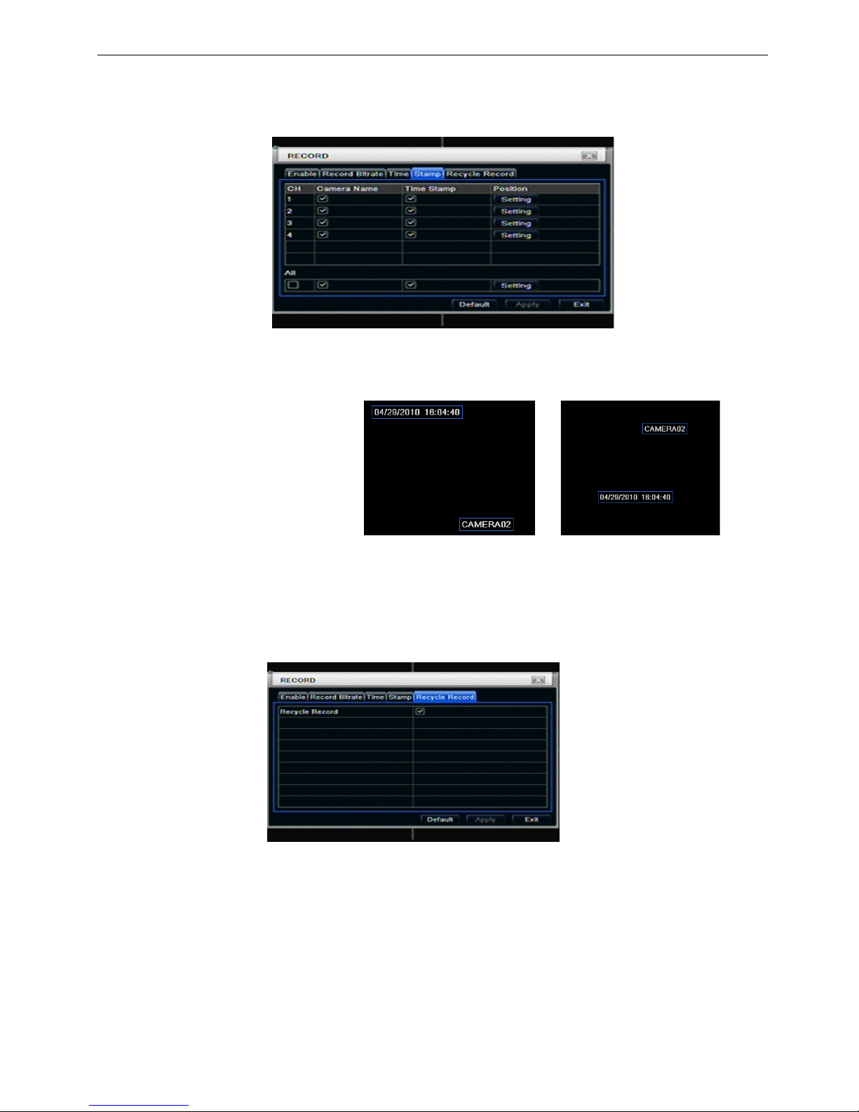
3.3.4 Stamp
Stamp:User can overlap the channel name and time stamp on video.
Step1: enter into system configuration record configuration stamp; refer to Fig 4-13:
Fig 4-13 record configuration-stamp
Step2: tick off camera name, time stamp; click Set button, user can use cursor to drag the camera name and
time stamp in random positions, refer to below Figures:
Before drag after drag
Step3: user can setup all channels with same parameters, tick off “all”, then to do relevant setup.
Step4: click “default” button to resort default setting; click “apply” button to save the setting; click “exit” button
to exit current interface.
3.3.5 Recycle reco rd
Step1: enter into system configurationrecord configurationrecycle record;
Step2: tick off recycle record, the recycle record f unction will enabl e, it will cover the earli er recorded files
and keep recoding when HDD is full; if disenable this function, it will stop recording when HDD is full.
Step3: click “default” button to reset default setting; click “apply” button to save the setting; click “exit” button
to exit current interface.
3.4 Schedule configuration
Schedule configuration includes three sub menus: schedule, motion and alarm.
3.4.1 Schedule
The volume means the seven da ys of a week fr om Monday to Sunday, the row means 24 hours of a day.
Click the grid to do relevant setup. Blue means checked area, gray means unchecked area.
 Loading...