

okidokeys Smart-Lock Installation Manual

Smart-Lock Installation Guide V10.pdf 1 11/4/2014 12:05:48 PM
Insert and tighten the
11
T-10 (Torx) screw in the
bottom of the
Smart-Lock cover.
Note: This screw is not
mandatory, but it
protects against
undesired access to
the inside of the lock.
The installation process is complete.
12
You are now ready to register your
Smart-Lock online.
Create your account at:
13
https://portal.okidokeys.com
Register your Smart-lock according
to the online instructions.
SMART-LOCK
INSTALLATION GUIDE
You can view the OKIDOKEYS Smart-Lock
installation video online at:
www.okidokeys.com/installation,
If you purchased a Smart-reader,
please install it before going through
the registration process.
C
M
Y
CM
MY
CY
CMY
K
Your metal keys.
Your existing metal keys are still working with your new OKIDOKEYS Smart-Lock. To achieve this, your Smart-Lock motor will
operate some cycles after each locking or unlocking, to reach its original position and be ready for next move.
The motor is also programmed to reposition your Smart-Lock to its previous position (locked or unlocked) in case of incomplete
manual operation. In this case, you will hear a sound and the motor moving.
If you need further assistance, let us help.
You can find additional help and information at our OKIDOKEYS support forum at:
support.okidokeys.com
For additional support, returns, or questions, please contact us through any of the following methods (all times are Eastern Time)
Visit our website: www.okidokeys.com
Call: 888-853-2309 | Monday–Friday 8 a.m. to 8 p.m. | Saturday 10 a.m. to 4 p.m.
Email: support@okidokeys.com
or scan the QR code.
1 - Install your Smart-Lock
2 - Create your account on
portal.okidokeys.com and register
your Smart-Lock
3 - Create users and assign them to
your Smart-Lock
4 - Install the OKIDOKEYS App and
synchronize your Smart-Lock
FCC/IC Regulatory notices.
Modification statement:
Practical House has not approved any changes or modifications to this device by the user. Any changes or modifications could void the user’s authority to operate the equipment.
Interference statement:
This device complies with Part 15 of the FCC Rules and Industry Canada licence-exempt RSS standard(s). Operation is subject to the following two conditions: (1) this device may not cause interference, and (2) this
device must accept any interference, including interference that may cause undesired operation of the device.
Wireless notice:
This device complies with FCC/IC radiation exposure limits set forth for an uncontrolled environment and meets the FCC radio frequency (RF) Exposure Guidelines and RSS‐102 of the IC radio frequency (RF) Exposure
rules. This transmitter must not be co-located or operating in conjunction with any other antenna or transmitter.
FCC Class B digital device notice:
This equipment has been tested and found to comply with the limits for a Class B digital device, pursuant to part 15 of the FCC Rules. These limits are designed to provide reasonable protection against harmful
interference in a residential installation. This equipment generates, uses and can radiate radio frequency energy and, if not installed and used in accordance with the instructions, may cause harmful interference to
radio communications. However, there is no guarantee that interference will not occur in a particular installation. If this equipment does cause harmful interference to radio or television reception, which can be
determined by turning the equipment off and on, the user is encouraged to try to correct the interference by one or more of the following measures:
- Reorient or relocate the receiving antenna.
- Increase the separation between the equipment and receiver.
- Connect the equipment into an outlet on a circuit different from that to which the receiver is connected.
- Consult the dealer or an experienced radio/TV technician for help.
CAN ICES-3 (B) / NMB-3 (B):
This Class B digital apparatus complies with Canadian ICES-003.
Keep batteries away from children. • Do not mix old and new batteries or alkaline, standard, or rechargeable batteries. • Replace batteries when any function fails to operate. • Do not dispose of product or batteries in fire.
Do not dispose of in household waste. Batteries contain substances that can be damaging to the environment and health. Contact local authority for recycling or collection information.
© 2014, Practical House. All rights reserved. Under the copyright laws, this document may not be copied, in whole or in part, without the written consent of Practical House. The Practical House and Okidokeys names and Okidokeys logo
are trademarks of Practical House. U.S. Patents 8,565,725 and 8,620,268; other patents pending in the US and in other countries
IMPORTANT:
Before you begin the Smart-Lock installation,
ensure that your existing deadbolt engages
freely into the locked position. You should not
have to push, pull, or force the existing deadbolt
into position. If the deadbolt does not engage
freely into position, make the necessary adjust-
ments according to your existing deadbolt instal-
lation instructions.
Once the existing deadbolt engages freely into
the locked position, you are ready to begin
installing your Smart-Lock system.
Register and Sign In: portal.okidokeys.com
Learn More: www.okidokeys.com
Technical Support: support@okidokeys.com | 888-853-2309
Smart-Lock Installation Guide V10.pdf 2 11/4/2014 12:05:48 PM
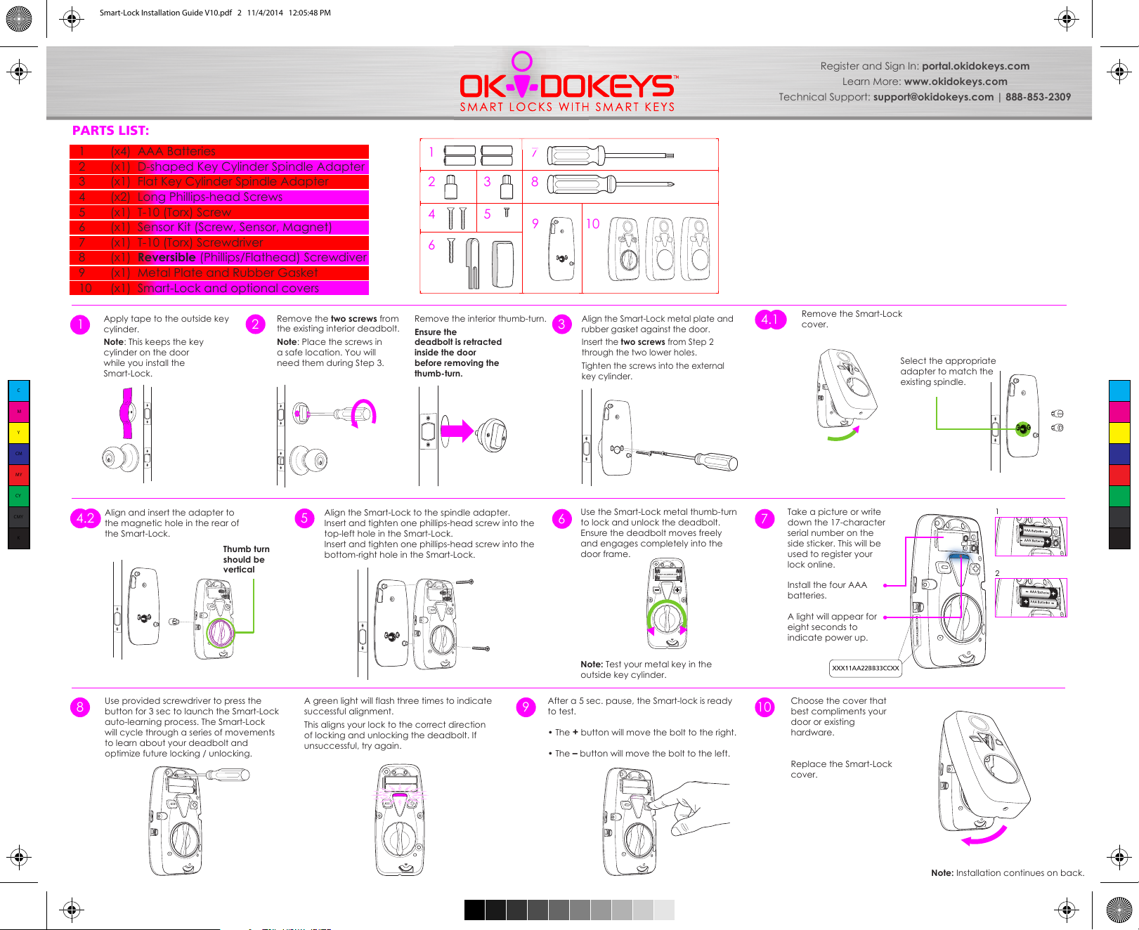
PARTS LIST:
1 (x4) AAA Batteries
2 (x1) D-shaped Key Cylinder Spindle Adapter
3 (x1) Flat Key Cylinder Spindle Adapter
4 (x2) Long Phillips-head Screws
5 (x1) T-10 (Torx) Screw
6 (x1) Sensor Kit (Screw, Sensor, Magnet)
7 (x1) T-10 (Torx) Screwdriver
8 (x1) Reversible (Phillips/Flathead) Screwdiver
9 (x1) Metal Plate and Rubber Gasket
10 (x1) Smart-Lock and optional covers
Register and Sign In: portal.okidokeys.com
Learn More: www.okidokeys.com
Technical Support: support@okidokeys.com | 888-853-2309
1
2
4
5
7
83
109
6
Apply tape to the outside key
1 3
cylinder.
Note: This keeps the key
cylinder on the door
while you install the
Smart-Lock.
C
M
Y
CM
MY
CY
CMY
K
Align and insert the adapter to
4.2
the magnetic hole in the rear of
the Smart-Lock.
Use provided screwdriver to press the
8
button for 3 sec to launch the Smart-Lock
auto-learning process. The Smart-Lock
will cycle through a series of movements
to learn about your deadbolt and
optimize future locking / unlocking.
Thumb turn
should be
vertical
Remove the two screws from
2
the existing interior deadbolt.
Note: Place the screws in
a safe location. You will
need them during Step 3.
Align the Smart-Lock to the spindle adapter.
5
Insert and tighten one phillips-head screw into the
top-left hole in the Smart-Lock.
Insert and tighten one phillips-head screw into the
bottom-right hole in the Smart-Lock.
A green light will flash three times to indicate
successful alignment.
This aligns your lock to the correct direction
of locking and unlocking the deadbolt. If
unsuccessful, try again.
Remove the interior thumb-turn.
Ensure the
deadbolt is retracted
inside the door
before removing the
thumb-turn.
9
Align the Smart-Lock metal plate and
rubber gasket against the door.
Insert the two screws from Step 2
through the two lower holes.
Tighten the screws into the external
key cylinder.
Use the Smart-Lock metal thumb-turn
to lock and unlock the deadbolt.
Ensure the deadbolt moves freely
and engages completely into the
door frame.
Note: Test your metal key in the
outside key cylinder.
After a 5 sec. pause, the Smart-lock is ready
to test.
• The
+ button will move the bolt to the right.
• The – button will move the bolt to the left.
10
Remove the Smart-Lock
4.1
cover.
Take a picture or write
76
down the 17-character
serial number on the
side sticker. This will be
used to register your
lock online.
Install the four AAA
batteries.
A light will appear for
eight seconds to
indicate power up.
Choose the cover that
best compliments your
door or existing
hardware.
Replace the Smart-Lock
cover.
Select the appropriate
adapter to match the
existing spindle.
1
2
Note: Installation continues on back.
 Loading...