

Page 1

MICROLINE 3320/3321
Troubleshooting Manual
with Components Parts List
All specifications are subject to change without notice.
Page 2

HP, LaserJet and PCL5e are trademarks of Hewlett-Packard Co.
Page 3

PREFACE
This manual describes in detail troubleshooting of the component parts for Microline
320/321 TURBO printer and provides a parts list.
Page 4

TROUBLESHOOTING MANUAL
Page 5

CONTENTS
1. OUTLINE ...................................................................................................1
2. TOOLS ......................................................................................................5
3. TROUBLESHOOTING TABLES ...............................................................5
4. TROUBLESHOOTING FLOWCHART ......................................................7
5. CIRCUIT DIAGRAM
6. COMPONENT PARTS LIST
Page 6
1. OUTLINE
This troubleshooting flowchart has been prepared for the repair of each board assembly of the
Microline 320/321 TURBO printer. The repairmen using this manual are assumed to be familiar
with certain techniques.
1.1 Items to Check Before Repair
• Check the inspection items specified in the instruction manual.
• Find out as many details of the trouble as possible from the customer.
• Inspect in the conditions as close as possible to those at the time the trouble occurred.
• Proceed with the repair as follows:
Check the trouble status according to Table 1.1 for the details of the trouble. Then, locate the
trouble position according to the detailed flowchart.
• Carry out a thorough test after the repair to check for correct functioning.
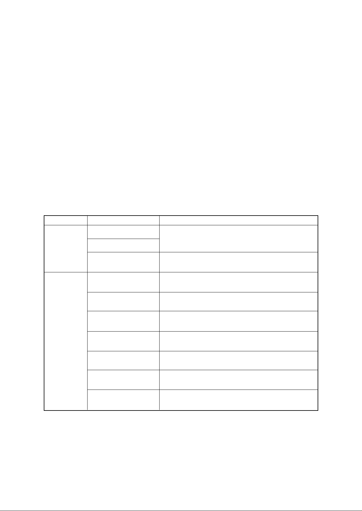
1.2 Troubleshooting
Trouble contents Surmise of troublleStatus
Table 1.1
Trouble upon
power on
Trouble
during
printing
Power is not supplied
No spacing operation
Homing does not end
normally
Paper jam while paper
insertion
Smearing/Missing dots
Faint or dark print
Ribbon feed trouble
Line feed trouble
Malfunction of switch on
operation panel.
Data receiving failure
Transformer, Power & Control Board, Driver Board, Operation Panel.
Space motor, carriage Cable, Print Head.
Space Motor, Carriage Cable, Spacing Mechanism, Driver Board
Pressure roller Mechanism, Support Protector, Pull up roller cover.
Print Head, Power & Control Board, Space Motor, Carriage Cable,
Driver Board
Print Head, Ribbon feed assembly, Power & Control Board, Driver
Board
Ribbon feed assembly, Space motor, Power & Control Board, Driver
Board
LF motor, Platen assy, LF mechanism, Power & Control Board, Driver
Board
Operation Panel, Power & Control Board, Driver Board
Power & Control Board, (I/F/P.C.B), I/F Cable, Menu setting, Driver
Board
Note: Refer to the Maintenance Manual for the troubleshooting flow chart of this table.
- 1 -
Page 7
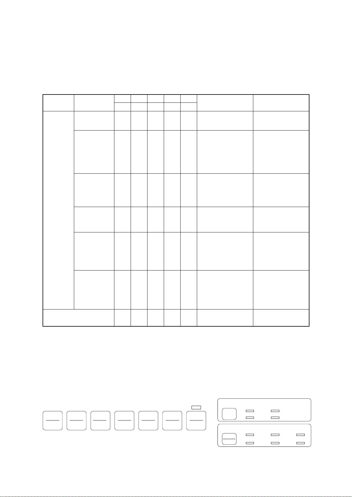
1.3 Lamp Display
(1) Printer mode display
Table 1.2
ALARM
CATEGORY
OPERATOR
ALARM
ALARM CONTENTS TROUBLESHOOTING
Paper end
alarm
Paper
change lever
alarm
ALARM MENU 10 CPI 15 CPISEL
ON
—
ON
OFF
—
—
—
BLINK
1
—
From, cut sheet or
bottom paper end
OFF
Change lever is set to
TOP position while
paper is already inserted
from rear or bottom.
Set New paper.
• Set the lever to
specified position.
• Check rear sensor
lever.
• Replace Power &
Control Board.
Paper jam alarm
Print Head
thermal alarm
ON
OFF
OFF
—
—
BLINK
1
OFF
—
BLINK
• Cut sheet could not be
1
ejected.
• Cut sheet could not be
fed properly.
—
Print head temperature
exceeds 119°C.
• Remove the paper or
check feed
Mechanism.
• Press SEL key.
• Wait until it is cooled.
• Replace P.H. or Power
& Control Board.
Space motor
thermal alarm
OFF
—
BLINK
1
—
—
Temperature of space
motor and driver
exceeds specified value.
• It is recovered
automatically.
• Replace SP motor or
Power &Control
Board.
LF motor
temperature
OFF
—
BLINK
1
alarm
FATAL ALARM
BLINK
OFF
OFF
2
Note: BLINK 1: 400 ms ON, 400 ms OFF
BLINK 2: 200 ms ON, 200 ms OFF
— : LED is kept in Current Condition (no change)
(2) Fault alarm display
When the printer detects any of the various alarm states, the information is displayed as
shown below on the operation panel. The alarm is specified by lamp combination of PRINT
QUALITY and CHARACTER PITCH. (See Table 1.3 for details.)
SEL
SEL
MENU
EXIT
POWERALARM
SHIFT
LF
Micro Feed
Down
GROUP ITEM SET
FF/LOAD
Micro Feed
Up
TEAR PARK QUIET
MENU
—
PRINT
—
Temperature of LF
motor and driver
exceeds specified value.
Hardware Alarm has
occurred.
TOF
• It is recovered
automatically.
• Replace LF motor or
Power & Control
Board.
See Table 1.3.
PRINT QUALITY
CHARACTER PITCH
RESET
HSD UTILITY
NLQ SSD
10
17
12
20
15
PROP
- 2 -
Page 8
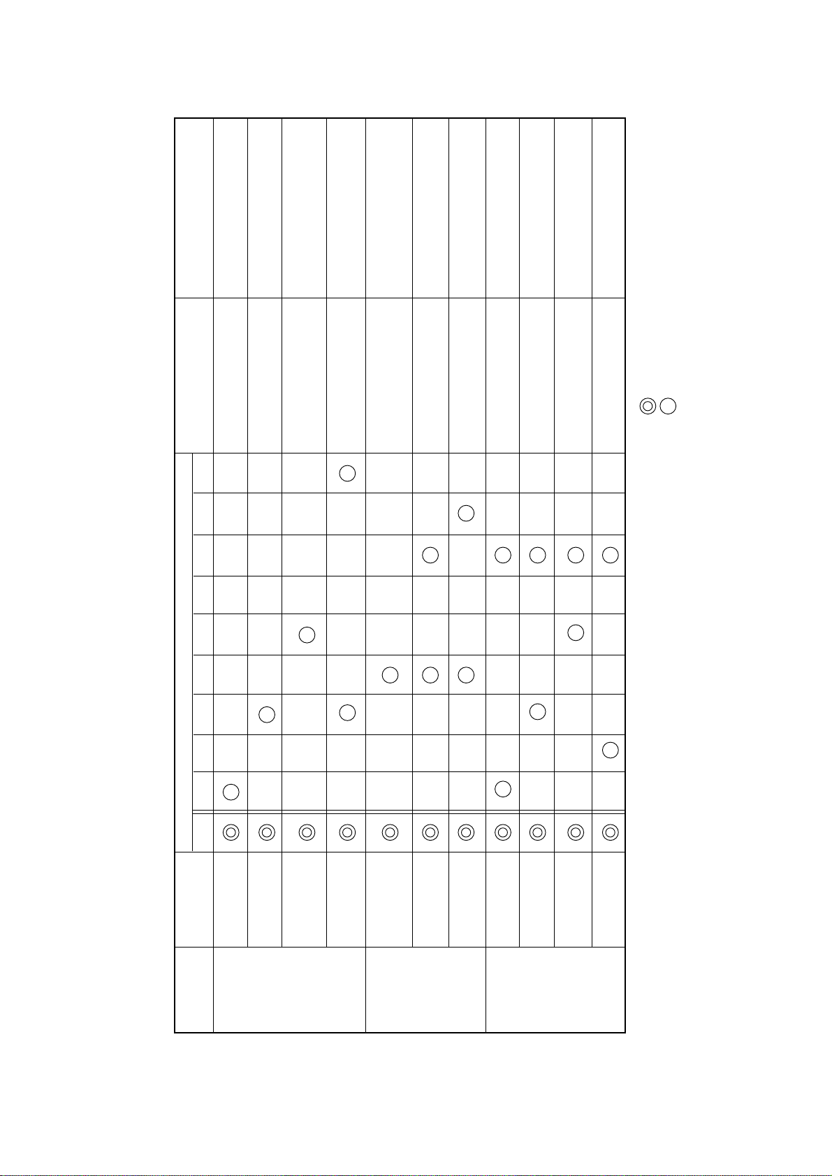
REMARKS TROUBLESHOOTING
Table 1.3 (1/2)
LED DISPLAY
Replace Power & Control Board
Replace ROM or Power & Control
Board
Read/write error
Check sum error
Replace Power & Control Board
Read/write error
Replace Power & Control Board
No reaction when MPU
reads data
Turn the power OFF and ON or
replace Power & Control Board
Replace Power & Control Board
Replace ROM or Power & Control
Board
Replace I/F Board
MPU is locked up and it is
reset after 65 ms.
NMI port of MPU is kept
low level.
FFFF data is detected
due to MPU locked up.
Read/write error
Replace I/F Board
Replace I/F board or Power & Control
Replace ROM on I/F Board or
I/F Board
Read/write error
Check sum error
Board
: LED Blink (200 ms ON, 200ms OFF)
No reaction from serial I/F
Board
: LED Lights up.
(3) Fatal Alarm
ALARM 10 12 15 17 20 PROP HSD UTL NLQ
ALARM
ALARM
CATEGORY
MPU internal
RAM alarm
Program
ROM alarm
RAM on
MAIN
CONTROL
Control Board
alarm
EEPROM
alarm
ALARM
WDT (Watch
Dog Timeout)
alarm
FIRMWARE
DETECTION
- 3 -
NMI signal
alarm
BRK instruction
ALARM
alarm
MPU internal
RAM alarm
ROM alarm
SERIAL
RAM on I/F
board alarm
INTERFACE
ALARM
I/F not
mounted
Page 9
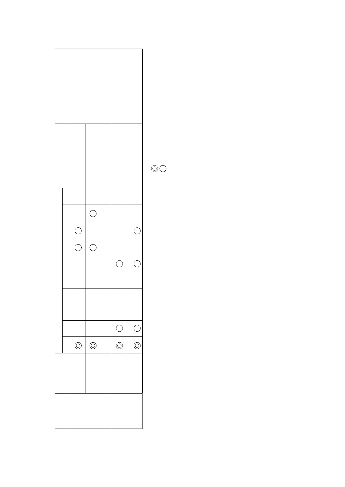
• Replace space motor.
REMARKS TROUBLESHOOTING
Space IPT is not occurred
Table 1.3 (2/2)
LED DISPLAY
• Replace P.H. cable.
• Replace Power & Control Board.
• Replace Driver Board.
• Check the mechanism if
load is too much.
• Check the P.H. connection.
• Replace Print Head.
• Replace P.H. cable.
within in specified timing.
Print head does not reach
to the home position.
Thermister is open, short
with 0V or short with +5V.
• Replace Driver Board.
: LED Blink (200 ms ON, 200ms OFF)
: LED Lights up.
ALARM 10 12 15 17 20 PROP HSD UTL NLQ
ALARM
ALARM
CATEGORY
Spacing alarm
Print Head
mounting alarm
SPACING
ALARM
PRINT HEAD
A/D alarm
Print Head
PRINT HEAD
ALARM
Gap AD alarm
- 4 -
Page 10

2. TOOLS
In addition to the general maintenance tools, the following are necessary:
– Oscilloscope : Approx. 100 MHz or more
– Soldering iron : Standard (A soldering iron with a thin tip is best.)
3. TROUBLESHOOTING TABLES
1 The power source can not be turned on.
2 Only the POWER lamp lights. (The printer does not work.)
3 The printer alarm is displayed.
3-1 Printer Internal RAM Alarm
3-2 S-I/F Internal RAM Error
3-3 S-I/F Connection Alarm
3-4 Program ROM Alarm
3-5 S-I/F ROM Alarm
3-6 EEPROM Alarm
3-7 WDT Alarm, BRK Command Alarm
3-8 NMI Alarm
3-9 Printer External RAM Alarm
3-10 S-I/F External RAM Alarm
3-11 SPACING Alarm, HOMING Alarm
3-12 Head A/D Alarm
3-13 Head Gap A/D Alarm
4 Wrong characters are printed or some characters are not printed.
5 Defective line feed.
6 When pressing the operation switch, it does not work.
6-1 The SEL switch does not work.
6-2 The SHIFT switch does not work.
6-3 The LF switch does not work.
6-4 The FF switch does not work.
6-5 The TEAR switch does not work.
6-6 The PARK switch does not work.
6-7 The QUIET switch does not work.
6-8 The PRINT QUALITY switch does not work.
6-9 The CHARACTER PITCH switch does not work.
- 5 -
Page 11

7 DATA can not be received.
7-1 Parallel interface data can not be received.
7-2 When receiving with the parallel interface, printed data is skipped, or the printer
does not work.
- 6 -
Page 12

4 TROUBLESHOOTING FLOWCHART
1 The power source can not be turned on. (The POWER lamp does not light.)
• Check the connection between Transformer and Power & Control Board and Driver
Board and Operation panel.
• No Be sure the connection.
▼
• Yes Is Fuse (F1) on Filter PCB blown out?
• Yes Replace Fuse (F1).
▼
• No Are the signal level between 1-pin and 8-pin of CN1 on Power & Control Board,
29 Vac, between 3-pin and 6-pin, 8 Vac, and between 4-pin and 5 pin, 10 Vac?
• No Replace Transformer.
▼
• Yes Is the voltage level at VCC (1-pin) of Q6 of the Power & Control Board, +8V?
• No Is fuse (F1) on Power & Control Board blown out?
• Yes Replace Fuse (F1)?
▼
• No Replace D6, D7, D8 and D9 of the Power & Control Board.
▼
• Yes Is the voltage level between one side and the other of C25 of the Power &
Control Board, +5V?
• No Replace Q6 or TR6 of the Power & Control Board.
▼
• Yes Is +5V supplied for CN3 of the Driver board?
+5V (CN3 – 3 pin)
0V (CN3 – 2 pin)
• No Check +5V supplied for the Driver board or replace Driver board?
▼
• Yes Is +5V supplied for CN1 of the operation panel board?
+5V (CN1 – 5 pin)
0V (CN1 – 6 pin)
• No Replace a cable in the operation panel or replace the operation panel.
▼
• Yes Replace D2 or R2 on the operation panel.
- 7 -
Page 13
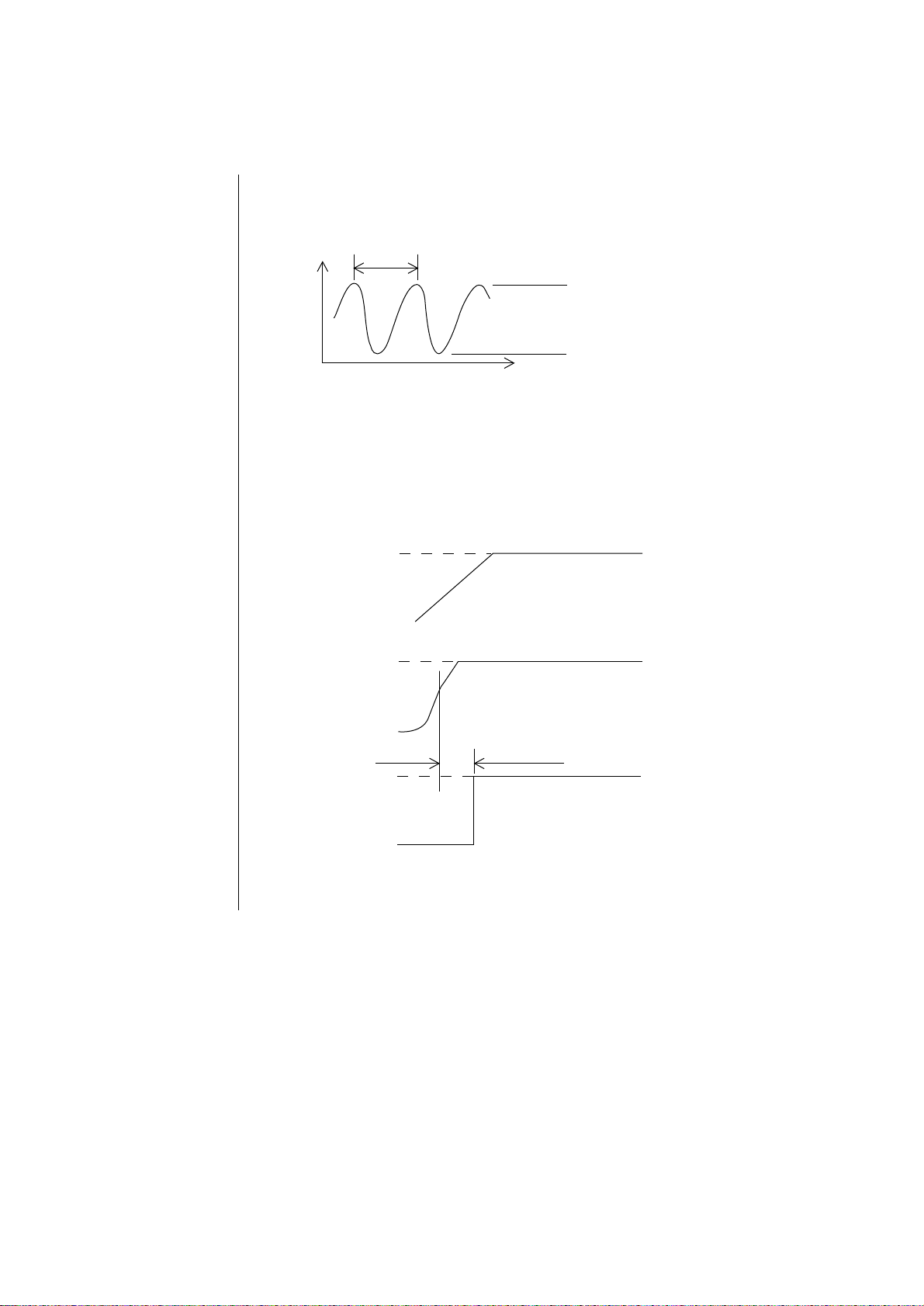
2 Only the POWER lamp lights. (The printer does not work.)
• Does the oscillating waveform from OSC of the Power & Control Board have the form
shown in Figure 1 below?
81.4 ns
V
(V)
T(ns)
+4 V ~ +5 V
0 V ~ 1V
Fig. 1
• No Replace OSC of the Power & Control Board.
▼
• Yes Does the RST-N signal have the waveform shown in Figure 2 below (with
+5 V and +8V signals as reference)?
+8 V
+8 V
0
+5 V
+5 V
0
+5 V
RST-N
0
Fig. 2
▼
• No If RS232C PCB is available, replace the RS232C PCB.
If the RS232C PCB is not available, replace the Power & Control
Board.
- 8 -
Page 14
▼
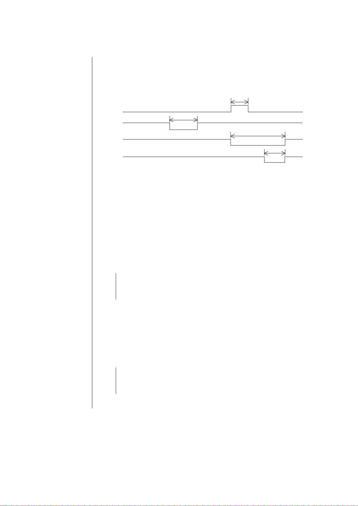
• Yes Do bus line signals of 4C (67 x 640) of the Power & Control Board such as ALEP, PSEN-N, LSICS-N and RDN/WRL-N have waveforms as shown in Fig. 4?
62 ms
ALE-P
102 ms
PSEN-N
203 ms
LSICS-N
76 ms
RD-N/WRL-N
+5V
0V
+5V
0V
+5V
0V
+5V
0V
Fig. 4
At the rising edge of PSEN-N and RD-N/WRL-N, the bus line level is decisively
set to “H” or “L”.
• No Replace Q501 of the Power & Control Board.
▼
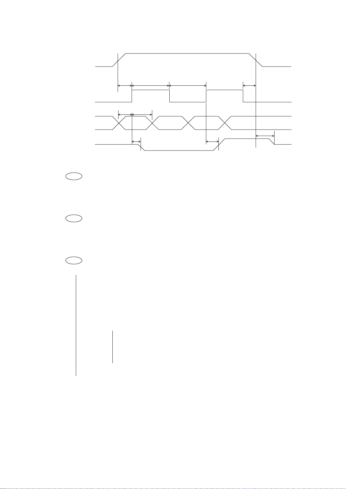
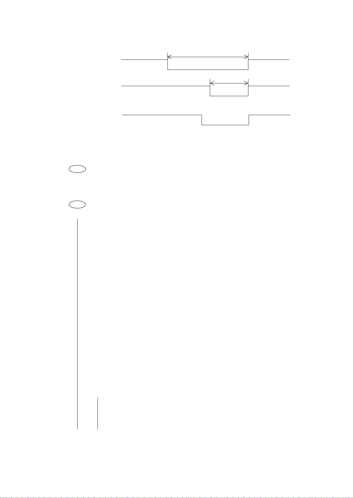
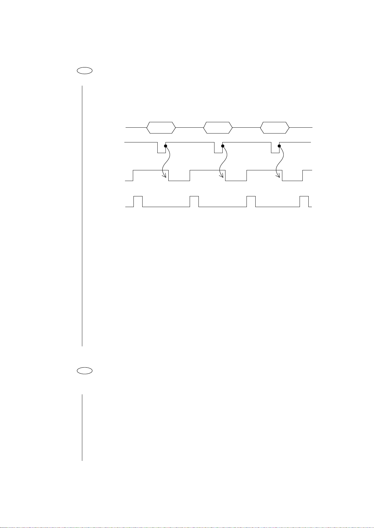
• Yes Does the OPCLK-N/OPTXD signal arrive at CN1 of the operation panel?
See Fig. 5.
OPCLK-N (CN1-3 pin)
OPTXQ (CN1-4 pin)
• No Is the flexible calbe of the operation panel connected without break?
• No Replace the flexible cable.
▼
• Yes Replace CN3 of the Driver Board.
▼
• Yes Does the OPRXD signal arrive at CN1 of the operation panel? See Fig. 5.
OPRXD (CN1-2 pin)
• No Replace IC1 of the operation panel.
▼
• Yes Does the OPRXD signal arrive at CN3 of the Driver Board? See Fig. 5.
• No Is the flexible cable of the operation panel connected without break?
• No Replace the flexible cable
▼
• Yes Replace CN3 of the Driver Board.
▼
• Yes Replace Q501 of the Power & Control Board.
- 9 -
Page 15

OPTXD
DATA
DATA
+5V
0V
OPCLK-N
OPRXD
DATA
Fig. 5
DATA
+5V
0V
+5V
0V
- 10 -
Page 16
3 The printer alarm is displayed.
3-1 Printer internal RAM alarm
• Replace Q501 of the Power & Control Board.
3-2 S-I/F internal RAM alarms.
• Replace Q3 of the LXHI board.
3-3 S-I/F connection alarm.
• Replace the LXHI board.
3-4 Program ROM alarm.
• Replace Q1 of the Power & Control Board (EPROM).
3-5 S-I/F ROM alarm.
• Replace Q3 of the LXHI board.
3-6 EEPROM alarm.
• Is the voltage of Q5-8pin +5V?
• No Check TR5 and TR7 and pattern on the Power & Control Board.
Correct pattern or replace parts.
▼
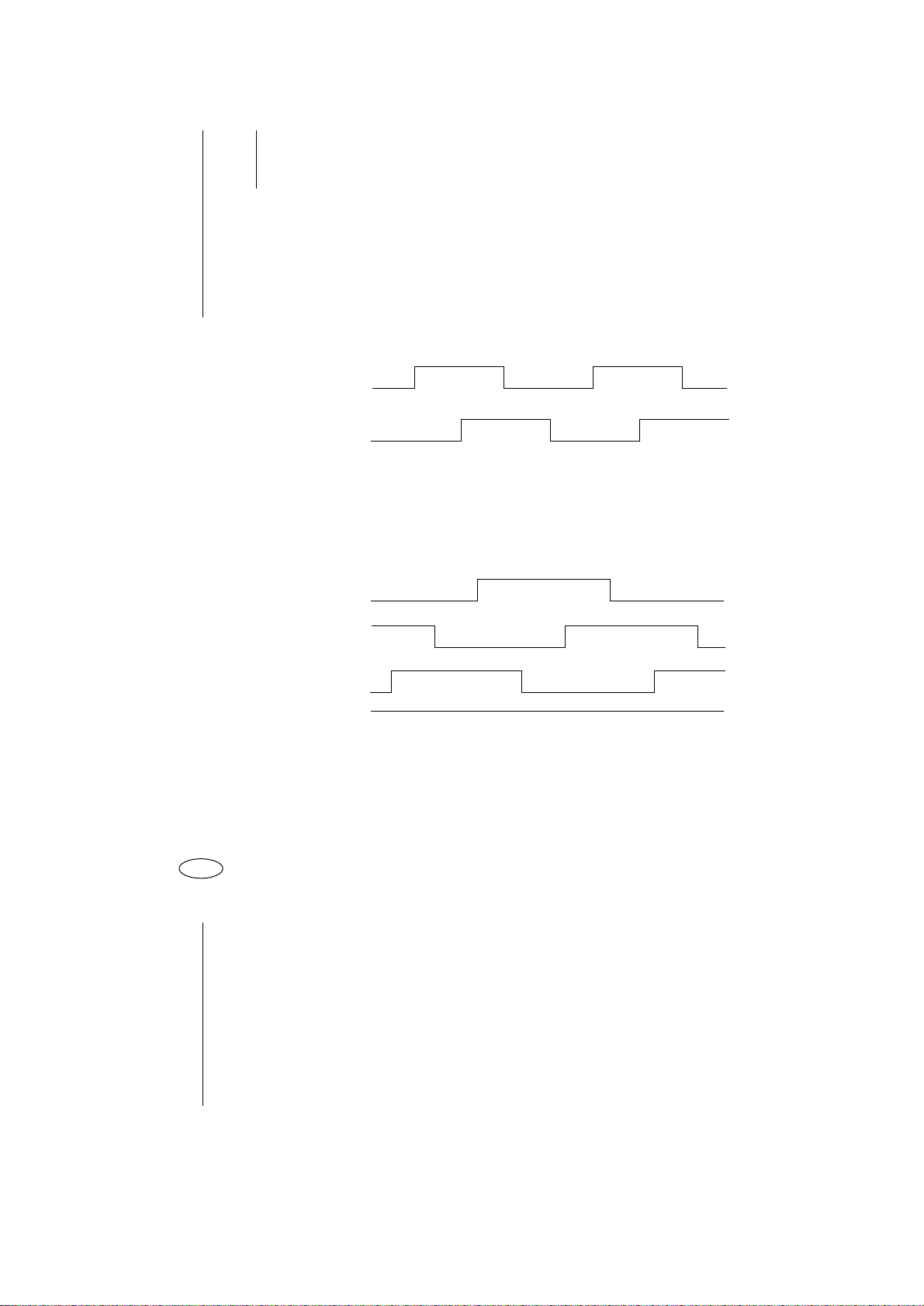
• Yes Do signals of Q501 of the Power & Control Board (67 x 640) such as EECLKP and EEDIN-P and EECS-P have the waveforms shown in Fig. 6?
• No Replace Q501 of the Power & Control Board.
▼
• Yes Do signals of Q5 of the Power & Control Board (EEPROM) such as EEDINP, EECS-P, EECLK-P and EEDOUT-P have the waveforms shown in Fig. 6?
• No Check EEDIN-P, EECS-P and EECLK-P patterns and parts
connected to the pattern. Correct pattern or replace parts.
▼
• Yes Replace Q501 of the Power & Control Board.
- 11 -
Page 17
EECS-P
+5V
0V
EECLK-P
EEDIN-P
EEDOUT-P
MIN
50 ns
MIN
100 ns
MIN
450 ns
MIN
100 ns
MIN
500 ns
Fig. 6
3-7 WDT alarm, BRK command alarm
• Is the alarm canceled by turning on power?
• No Replace ROM, Q1 or the Power & Control Board.
3-8 NMI alarm
• Is the alarm canceled by turning on power?
MIN
450 ns
MIN
500 ns
MIN
0 ns
MIN
100 ns
+5V
0V
+5V
0V
+5V
0V
• No Replae Power & Control Board.
3-9 Printer external RAM alarm.
• Do signal of Q3, Q4 (DRAM) of the Power & Control Board such as RAS-N, CAS-N, OE,
WE have the waveforms shown in Fig. 7?
RAS-N (Q3, Q4-5)
CAS-N (Q3, Q4-16)
RD-N (Q3, Q4-1)
WRL-N (Q3, Q4-4)
• No Is the dumping resistance of each signal broken?
Check Q502 (Power & Control Board)?
• Yes Replace the dumping resistance or Q502
▼
• No
▼
• Yes Replace Q3, Q4.
- 12 -
Page 18
RAS-N
CAS-N
103 ns
41.4 ns
+5V
0V
+5V
0V
RD-N/WRH-N/WRL-N
At the rising edge of OE, WE, the bus line level is decisively set to “H” or “L”.
Fig. 7
3-10 S-I/F external RAM alarm.
• Replace Q9 of the LXHI board.
3-11 SPACING alarm, HOMING alarm
• Is the fuse (F1) on the Driver board blown?
• Yes Replace F1.
▼
• No Is VNF of MTDV (HA13412) short-circuited to U0, V0, or W0?
VNF (MTDV-11 pin)
U0 (MTDV-13 pin)
V0 (MTDV-15 pin)
W0 (MTDV-17 pin)
+5V
0V
• Yes Replace MTDV
▼
• No Do signals of SPU, SPV, SPW and SPD-A of MTDV have the wave forms shown in
Fig. 10?
• No Check patterns SPU, SPV, SPW between Q501 and MTDV. When they are
OK, replace the Driver PCB Q501.
▼
• Yes Do signals of U0, V0, and W0 of the MTDV have the wave forms shown in Fig. 10?
• No Replace the HTDV PCB.
▼
• Yes Do signals of PHASE A and PHASE B have the wave forms shown in Fig. 9?
• No Is the connection between CN5 on the Driver Board, and the CN on the
carriage are OK?
• No Secure the connection.
▼▼
• Yes Is there any disconnection of cable between the Driver Board and the
carriage?
- 13 -
Page 19
• No Replace the Carriage.
▼
• Yes Replace the Cable.
▼
• Yes Do signals of PHASE A, PHASE B of Q501 have the wave forms shown in Fig. 9?
• No Check the parts and pattern between Q501 and CN6. Correct
pattern or replace parts.
▼
• Yes Replace Q501.
PHASE A
PHASE B
When the carriage is manually move.
Fig. 9
SPU
SPV
SPW
SPD-A
When the carriage is manually move.
+5V
0V
+5V
0V
+5V
0V
+5V
0V
+5V
0V
+5V
0V
Fig. 10
3-12 Head A/D alarm
• Is the voltage of the HTEMP-N signal of Q501 of the Power & Control Board (67 X 640) +5V?
HTEMP-N (Q501-62 pin)
• No Replace Q501.
▼
• Yes Is the connection of CN5 of the Driver Board secured?
• No Secure the connection of CN5.
▼
• Yes Replace the head.
- 14 -
Page 20

3-13 Head Gap A/D alarm
• Is the voltage of HDGAP-N Signal of Driver Board CN5 22 pin +5V?
• Yes Replace the Head cable or the carriage.
▼
• No Replace the Power & Control Board.
- 15 -
Page 21

4 Wrong characters are printed or some characters are not printed.
• Do signals of Q501 of the Power & Control Board (67 X 640) such as PSEN-N, LSICS-N,
RD-N, WRL-N, RAS-N and CAS-N have the wave forms shown in Figs. 4 and 7?
• No Replace Q501.
▼
• Yes Replace the head, Q501 of Driver board or the space motor.
- 16 -
Page 22
5 Defective line feed.
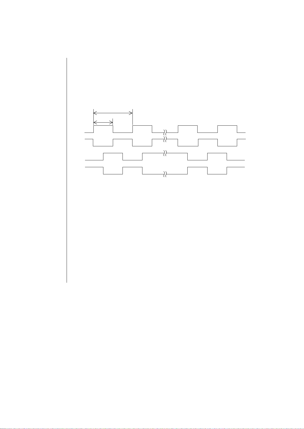
• Do signals of LFDV (Driver board) such as A1, A2, B1 and B2 have the waveforms shown
in Fig. 11?
A1 (LFDV-3 pin)
A2 (LFDV-7 pin)
B1 (LFDV-8 pin)
B2 (LFDV-12 pin)
4.44 ms
2.22 ms
A1
A2
+40V
0V
+40V
0V
B1
B2
Forward Reverse
Fig. 11
• No Replace LFDV.
LFDV (Driver Board)
When it does not work properly, replace Q501 or the Driver Board.
▼
• Yes Is the flexible cable connected without break?
• No Replace the flexible cable.
▼
• Yes Is the CN4 of the Driver Board broken?
• No Replace CN4
▼
• Yes Replace the LF motor.
+40V
0V
+40V
0V
- 17 -
Page 23
6 The printer does not operate though the operation switch is pressed.
• Do the OPCLK-N and OPTXD signals arrive at CN3? See Fig. 5.
• No Replace Q501 of the Driver board.
▼
• Yes Do the OPCLK-N and OPTXD signals arrive at CN1 of the operation panel?
See Fig. 5.
• No Is the flexible cable of the operation panel connected without break?
• No Replace the flexible cable.
• Yes Replace CN3 of the Driver board.
▼
• Yes Does the OPRXD signal arrive at CN1 of the operation panel?
• No Replace IC1 of the operation panel.
▼
• Yes Does the OPRXD signal arrive at CN3 of the Driver board? See Fig. 5.
• No Is the flexible cable of the operation panel connected without break?
• No Replace the flexible cable.
• Yes Replace CN3 of the Driver board.
▼
• Yes Go to steps 6-1 to 6-9 .
6-1 SEL SW does not work.
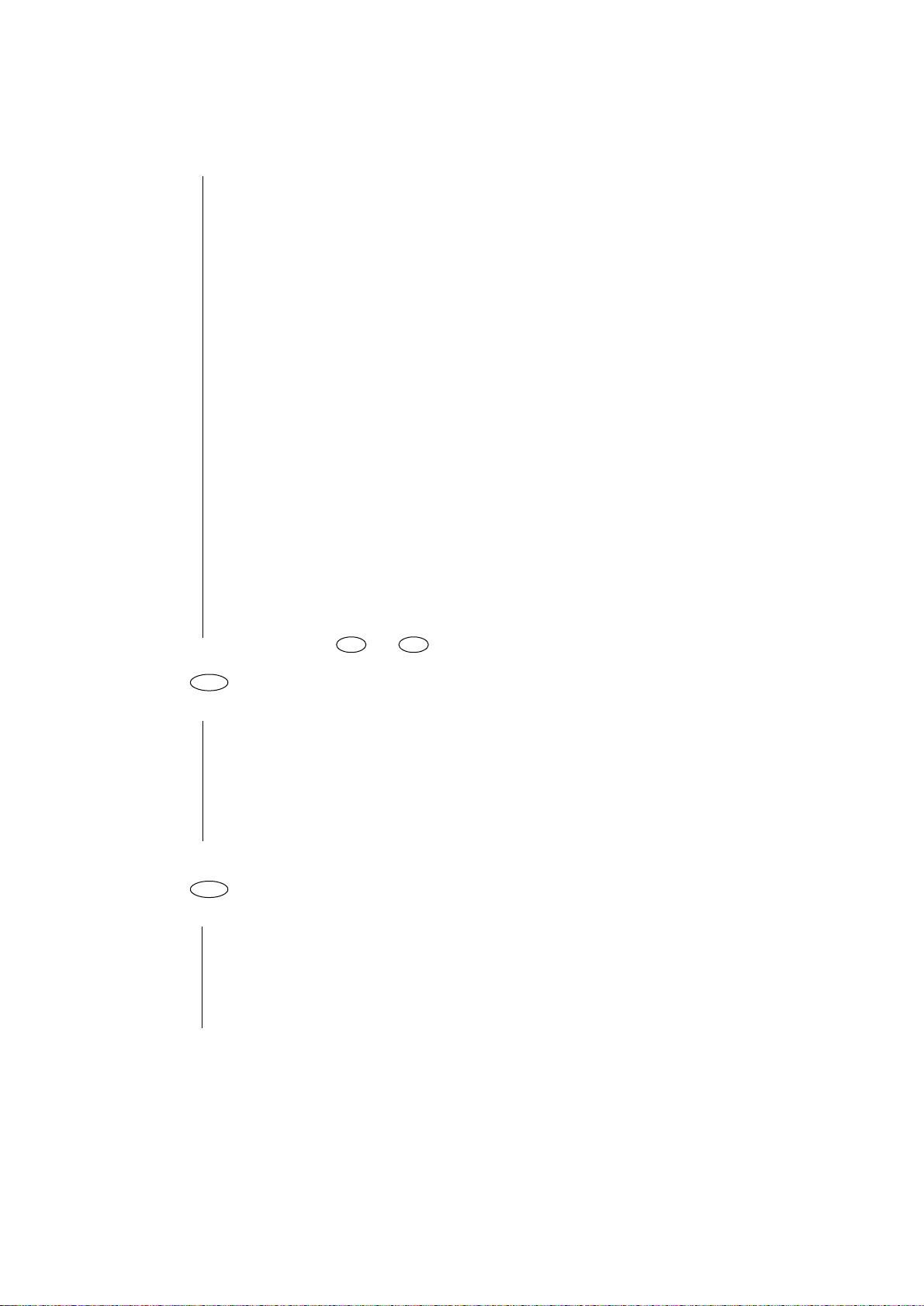
• When SWC2 of IC1 (Bu5148S) is set to “L”, is SWI4 set to “L” by pressing SEL SW?
SWC2 (C1-7 pin)
SWI4 (IC1-3 pin)
• No Replace SEL SW.
▼
• Yes Replace IC1 or Q501 of the Driver board.
6-2 SHIFT SW does not work.
• When SWC2 of IC1 is set to “L”, is SWI3 set to “L” by pressing SHIFT SW?
SWI3 (IC1-10 pin)
• No Replace SHIFT SW.
▼
• Yes Replace IC1 or Q501 of the Driver board.
- 18 -
Page 24

6.3 LF SW does not work.
• When SWC2 of IC1 is set to “L”, is SW1 set to “L” by pressing LF SW?
(IC1-18 pin)
SWI4 (ICI-3 pin)
• No Replace LF SW.
▼
• Yes Does LF SW recover IC1 or Q501 of the Driver board replaced?
• No Go to step 5.
6-4 FF SW does not work.
• When SWC2 of IC1 is set to “L”, is SWI2 set to “L” by pressing FF SW?
SWI2 (IC1-23 pin)
• No Replace FF SW.
▼
• Yes Does FF SW recover with IC1 or Q501 of the Driver board replaced?
• No Go to step 5.
6-5 TEAR SW does not work.
• When SWC1 of IC1 is set to “L”, is SWI4 set to “L” by pressing TEAR SW?
SWC1 (IC1-31 pin)
• No Replace TEAR SW.
▼
• Yes Does TEAR SW recover with IC1 or Q501 of the Driver board replaced?
• No Go to step 5.
6-6 PARK SW does not work.
• When SWC1 of IC1 is set to “L”, is SW2 set to “L” by pressing PARK SW?
• No Replace PARK SW.
▼
• Yes Does PARK SW recover with IC1 or Q501 of the Driver board replaced?
• No Go to step 5.
6-7 QUIET SW does not work.
• When SWC1 of IC1 is set to “L”, is SWI1 set to “L” by pressing QUIET SW?
• No Replace QUIET SW.
▼
• Yes Replace IC1 or Q501 of the Driver board.
- 19 -
Page 25

6.8 PRINT QUALITY SW does not work.
• When SWC3 of IC1 is set to “L”, is SWI1 set to “L” by pressing PRINT QUALITY SW?
• No Replace PRINT QUALITY SW.
▼
• Yes Replace IC1 or Q501 of the Driver board?
6-9 CHARACTER PITCH SW does not work.
• When SWC1 of IC1 is set to “L”, is SWI3 set to “L” by pressing CHARACTER PITCH SW?
• No Replace CHARACTER PITCH SW.
▼
• Yes Replace IC1 or Q501 of the Driver board.
- 20 -
Page 26
7 Data can not be received.
7-1 Parallel interface data can not be received.
• Do the IFDATA 1 to 8 signals of Q501 of the Driver board have the waveform shown in Figure
12 below?
IFD1 ~ 8
STB-N
BUSY-N
ACK
Valid Valid Valid
Fig. 12
• No Replace either relative electric component to the DATA 1 to 8 signals, or
replace CN6 of the Driver board.
▼
• Yes Does the STB-N signal of Q501 have the waveform shown in Fig. 12?
• No Replace either resistor or capacitor of the STB-N signal.
▼
• Yes Do the BUSY-N and ACK signals have the waveforms shown in Fig. 12?
H
L
H
L
H
L
H
L
• No Replace Q501.
BUSY-N (Q501-64 pin)
ACK (Q501-63 pin)
▼
• Yes Replace Q3.
7-2 When receiving with the parallel interface, printed data is skipped, or the printer
does not work.
• Gap in the self-test?
• Yes To step 4.
▼
• No Does the signal of BUSY-N or ACK of Q501 of the Driver board have the waveform
shown in Figure 12?
• No Replace Q501.
▼
• Yes Replace either relative electric component to ACK or BUSY-N signal, or replace Q3
of the Driver board.
- 21 -
Page 27

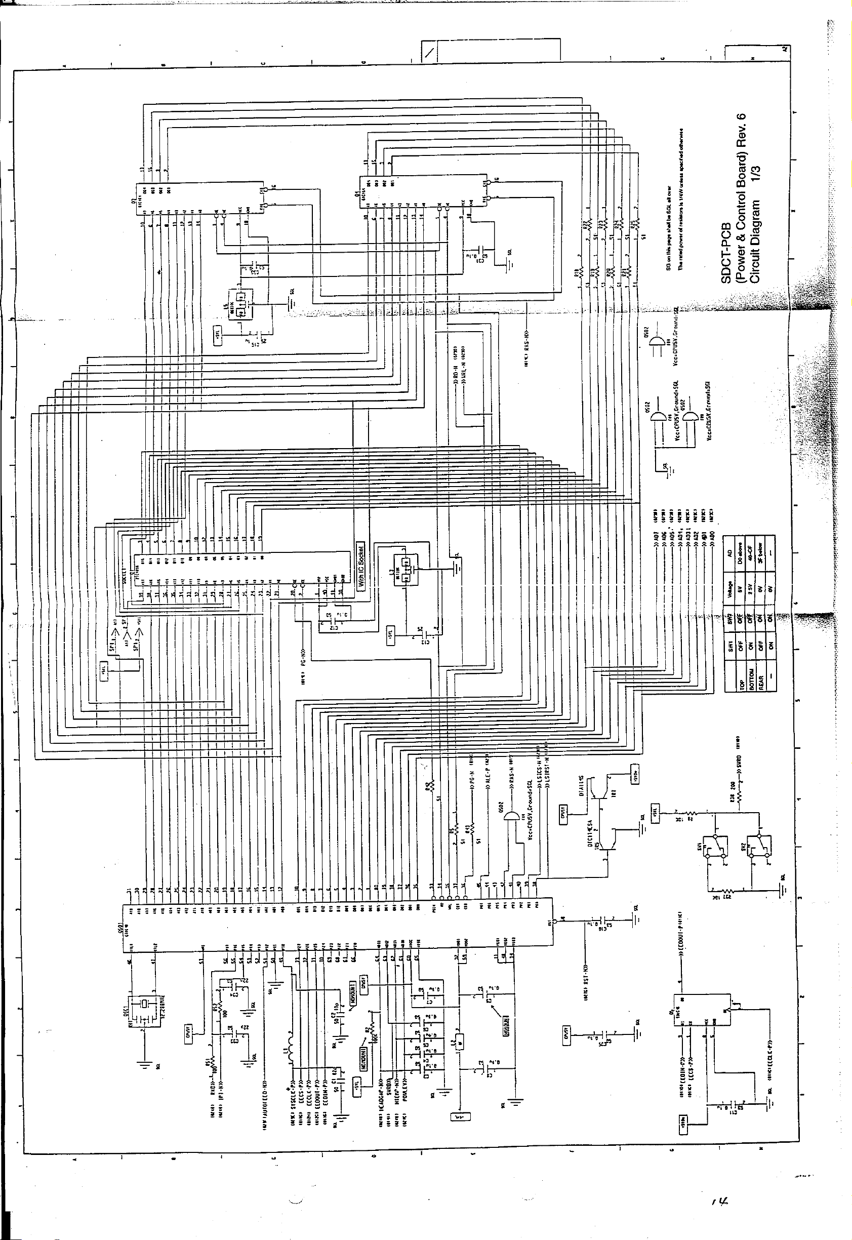
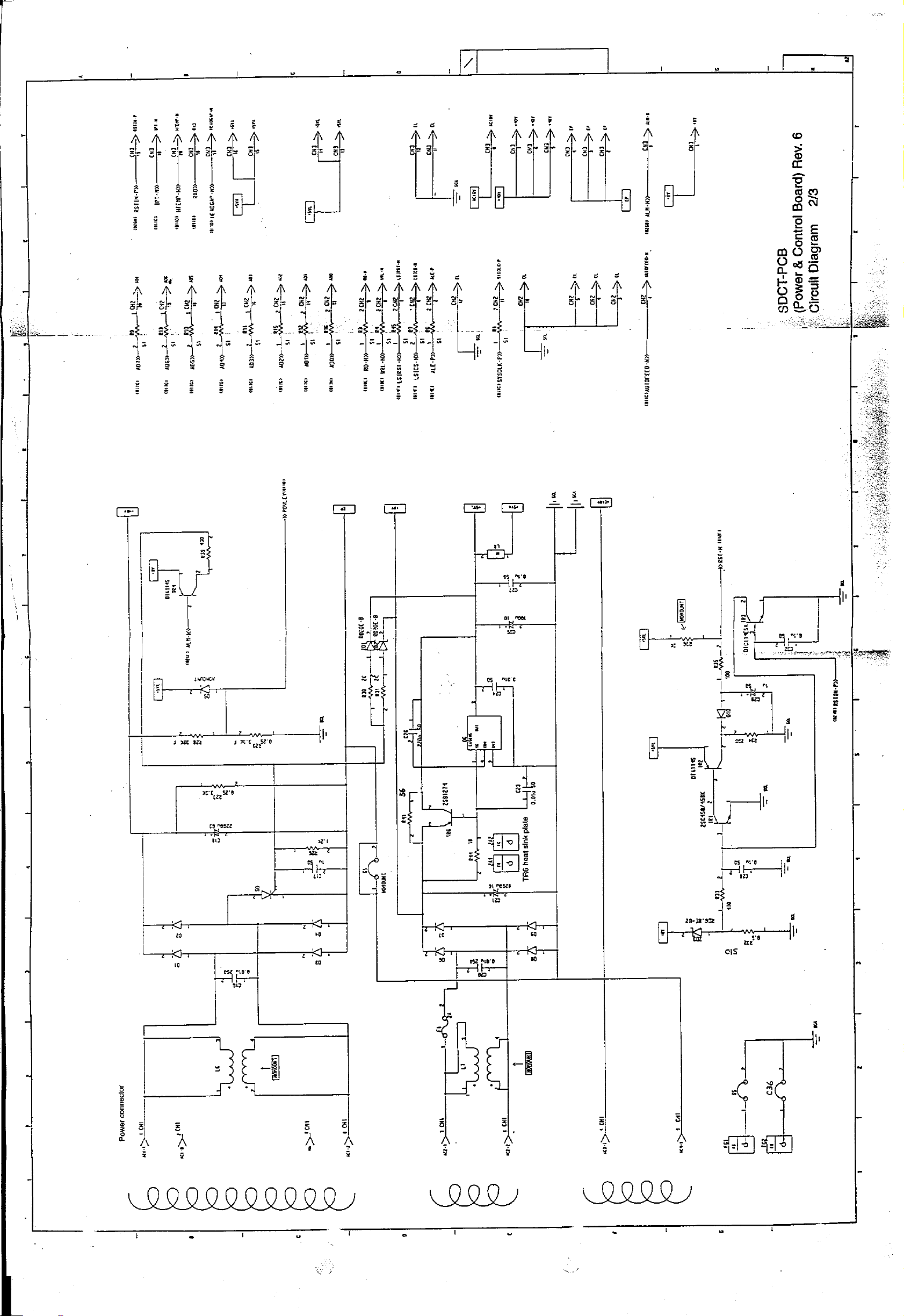
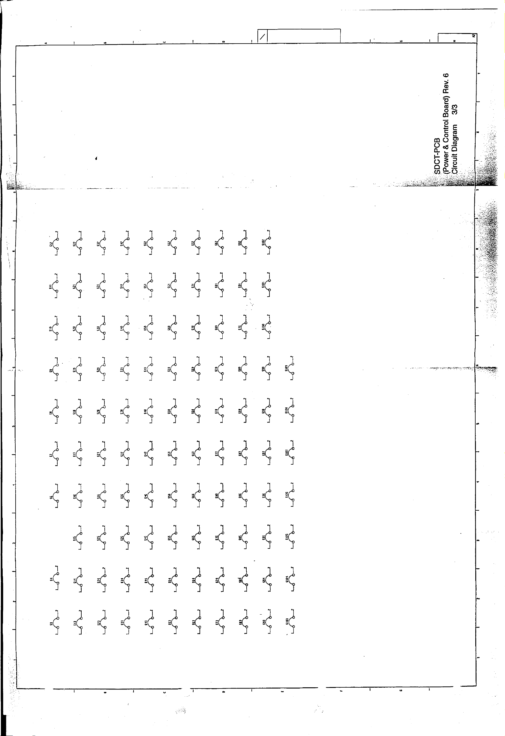
5. CIRCUIT DIAGRAM
SDCT-PCB (Power & Control Board) Rev. 6
SDDV-PCB (Driver Board) Rev. 4
LEOP-3 PCB (Operation Panel) Rev. 5 & 6
LXHI-PCB (Serial I/F Board) Rev. 7
Rev. 7
Rev. 8
Rev. 5
Rev. 6
Rev. 7
Page 28
Page 29
Page 30
Page 31

Page 32

Page 33

Page 34

Page 35

Page 36

Page 37

Page 38

Page 39

Page 40

Page 41

Page 42

Page 43

Page 44

Page 45

Page 46

Page 47

Page 48

Page 49

Page 50

Page 51

Page 52

Page 53

Page 54

Page 55

Page 56

Page 57

Page 58

Page 59

Page 60

Page 61

Page 62

Page 63

COMPONENT PARTS LIST
Page 64

6. COMPONENT PARTS LIST
SDCT-PCB (Power & Control Board) Rev. 6 4YA4042-1543 Gxxx
SDDV-PCB (Driver Board) Rev. 4 4YA4042-1549 G001
LEOP-3 PCB (Operation Panel) Rev. 5 & 6 4YA4042-1516 G003
LXHI-PCB (Serial I/F Board) Rev. 7 4YA4021-1050 G001
Drawing List
Rev. 7 (ODA, OEL, OKI-INT)
Rev. 8
Rev. 5
Rev. 6
Rev. 7
Page 65

Page 66

SDCT-PCB (Power & Control Board) Rev. 6
(4YA4042-1543Gxxx -2/6)
REF.
NO.
1
2
3
4
5
6
7
SYMBOL TYPE/NAME PART NO. Q'TY REMARKS
D6-D9
D1-D4
D10
D5
ZD3
ZD1, ZD2
R26
EM01Z/SM1XN02/DSM1D2
Rectifier DI
DSA3A2
Rectifier DI
1SR004-40
Rectifier DI
1S953/1S2075K/1S2473
Signal DI
RD6.8E-B2
Zener DI
RD20E-B
Zener-DI
RD14DX2E-1.2KΩJ
RD Resistor
610A0003M0001
610A0021L0092A
610A0303M0004
611A0003L0001
613A1231L0142B
613A1231L0252
321A1023J0122
4
4
1
1
1
2
1
8
R35, R51, R52, R5
9
R8, R37
10
R34, R38
11
R30, R31
12
R36
13
R39
14
R33
15
R1, R3, R4, R5, R7,
R9-R16, R18-R25,
R42, R43, R45
R44
16
RD14DX2E-100ΩJ
RD Resistor
RD14DX2E-10KΩJ
RD Resistor
RD14DX2E-200ΩJ
RD Resistor
RD14DX2E-2KΩJ
RD Resistor
RD14DX2E-27KΩJ
RD Resistor
RD14DX2E-430ΩJ
RD Resistor
RD14DX2E-470ΩJ
RD Resistor
RD14DX2E-51ΩJ
RD Resistor
RD14DX2E-18ΩJ
RD Resistor
321A1023J0101
321A1023J0103
321A1023J0201
321A1023J0202
321A1023J0273
321A1023J0431
321A1023J0471
321A1023J0510
321A1023J0180
4
2
2
2
1
1
1
24
1
- 2 -
Page 67

SDCT-PCB (Power & Control Board) Rev. 6
(4YA4042-1543Gxxx -3/6)
REF.
NO.
17
R32
18
R29
19
R28
20
R27
21
R41
22
S50
23
C16, C20
24
C3-C8, C10, C12, C17,
C27, C28, C30-C32,
C35
SYMBOL TYPE/NAME PART NO. Q'TY REMARKS
RD1/2Y110ΩJ
RD Resistor
RNM1/4C2-3.3KΩJ
RD Resistor
RNM1/4C2-39KΩJ
RD Resistor
MOR2B3.3KΩJ
RS Resistor
MOR2B56ΩJ
RS Resistor
RD1/4Y100ΩJ
RD Resistor
TCK45F2E103ZYA 250V
CK Capacitor 10000PF
CK92F1H104ZY 50V
CKCapacitor 0.1UF
321A1431J0111
323A4024F0332
323A4024F0393
324A1121J0332
324A1121J0560
321A1421J0101
302A4027Z5103
303A0420Z3104
1
1
1
1
1
1
4
15
25
C1
C13, C15
26
27
C23, C24
C33, C34, C38, C39
28
29
C26
30
C25
C21
31
32
C29
C18
33
FK16C0G1H820J 50V
CC Capacitor 82PF
CK92F1E105ZS 25V
CK Capacitor 1UP
CK92C1H103MS 50V
CK Capacitor 0.01UF
CC122CH1H220K 50V
CC Capacitor 22PF
FK16C0G1H221J 50V
CC Capacitor 220PF
SME10VB-100-OA 10V
CE Capacitor 100UP
16VBSN-8200 (M) 16V
CE Capacitor 8200UF
50MS5-1M 50V
CE Capacitor 1UF
UVX1J222MRAY-1CA 63V
CE Capacitor 2200UF
303A1014C3820
303A4117Z2105
303A4115M3103
303A1006C9220
303A1014C3221
304A1123A1101
304A1037C9822
304A1046H1109
304A1086J1222
1
2
2
4
1
1
1
1
1
- 3 -
Page 68

SDCT-PCB (Power & Control Board) Rev. 6
(4YA4042-1543Gxxx -4/6)
REF.
NO.
34
35
36
37
38
39
40
SYMBOL TYPE/NAME PART NO. Q'TY REMARKS
C11
Q6
Q3, Q4
Q5
Q501
Q502
Q1
CK92C1H102MS 50V
CK Capacitor 0.001UF
LA5005
BIP Linear IC
MSM51C464A-80RS
MOS-D-RAM
93LC46A-NW
MOS-EEPROM
MSM67X640GS-BK
MOS-CPU (FP)
74F08FP
BIP Digital IC (SO)
DICF-40CS-E
IC Socket
303A4115M3102
720A1033M0001
802A0024F8301
816A0303M0000
851A0324N0007
700A9703N0008
245A1221P0400
1
1
2
1
1
1
1
41
L3, L5
42
L1
43
L2, L8
44
S3-S20, C36
45
S21-S33
46
S34-S46
47
S47-S49, S51-S63
48
S64-S75
DST306-55F103Z
EMI Filter
SBT-0210
Noise Filter
ZBF253D-01
Beads Filter
0.65 Tin-plated Annealed Copper
Wire
0.65 Tin-plated Annealed Copper
Wire
0.65 Tin-plated Annealed Copper
Wire
0.65 Tin-plated Annealed Copper
Wire
0.65 Tin-plated Annealed Copper
Wire
342A1004P2103
377A1108P0005
377A1115P1309
TA-0.65
TA-0.65
TA-0.65
TA-0.65
TA-0.65
2
1
2
19
13
13
16
12
- 4 -
Page 69

SDCT-PCB (Power & Control Board) Rev. 6
(4YA4042-1543Gxxx -5/6)
REF.
NO.
49
50
51
52
53
54
55
SYMBOL TYPE/NAME PART NO. Q'TY REMARKS
S77-S90
S76, S90-S109
F1
TR2, TR4, TR7
TR1
TR3, TR5
TR6
0.65 Tin-plated Annealed Copper
Wire
0.65 Tin-plated Annealed Copper
Wire
230002
Glass Tube Fuse
DTA114S
PNP-HF-TR
2SC458/458K
NPN-HF-TR
DTC114ESA
NPN-HF-TR
2SB1274
PNP-LF-TR
TA-0.65
TA-0.65
540A5013T2104
600A1035M0005
602A1003M0003
602A1035M0007
601A1232M0004
14
20
1
3
1
2
1
56
57
58
59
60
61
SO
SW1, SW2
CN1
CN2, CN3
TP1
SP1
CR3CM-8
Gate Thyristor OFF
D2A-1220
Microswitch
00-8263-0812-00-000
PC Connector
20FE-BT-VK-N
PC Connector
IMSA-9206H-GF
PC Connector
IMSA9202B-1-03Z013GF
PC Connector
620A0022M0006E
207A1041P0001
224A3357P0080
224A4134P0200
224A4080P0020
224A4082P0030
1
2
1
2
1
1
- 5 -
Page 70

SDCT-PCB (Power & Control Board) Rev. 6
(4YA4042-1543Gxxx -6/6)
REF.
NO.
6263OSC1
2
SYMBOL TYPE/NAME PART NO. Q'TY REMARKS
CST12.288MTW
Ceramic Oscillator
Heat Sink (GOT-2325-SPL)
381A1045B0017
PB4042-1548P001
1
1
- 6 -
Page 71

Page 72

Page 73

SDCT-PCB (Power & Control Board) Rev. 7 & 8
(4YA4042-1543Gxxx-3/6)
REF.
NO.
1
2
3
4
5
6
7
SYMBOL TYPE/NAME PART NO. Q'TY REMARKS
D6-D9
D1-D4
D5, D10, D11
ZD3
ZD1, ZD2
R26
R35, R51-R53, R5
EM01Z/SM1XN02/DSM1D2
Rectifier DI
DSA3A2
Rectifier DI
1S953/1S2075K/1S2473
Signal DI
RD5.6E-B
Zener DI
RD20E-B
Zener DI
RD14DX2E-1.2KΩJ
RD resistor
RD14DX2E-100ΩJ
RD resistor
610A0003M0001
610A0021L0092A
611A0003L0001
613A1231L0122
613A1231L0252
321A1023J0122
321A1023J0101
4
4
3
1
2
1
5
R8, R37
8
R38
9
R30, R31, R34
10
R36
11
R39
12
R33
13
R1, R3, R4, R6, R7,
14
R9-R16, R18-R25,
R42, R43, R45, S111
R54
15
R44
16
RD14DX2E-10KΩJ
RD resistor
RD14DX2E-200ΩJ
RD resistor
RD14DX2E-2KΩJ
RD resistor
RD14DX2E-27KΩJ
RD resistor
RD14DX2E-430ΩJ
RD resistor
RD14DX2E-4.3KΩJ
RD resistor
RD14DX2E-51ΩJ
RD resistor
RD14DX2E-5.6KΩJ
RD resistor
RD14DX2E-18ΩJ
RD resistor
321A1023J0103
321A1023J0201
321A1023J0202
321A1023J0273
321A1023J0431
321A1023J0432
321A1023J0510
321A1023J0562
321A1023J0180
2
1
3
1
1
1
25
1
1
- 9 -
Page 74

SDCT-PCB (Power & Control Board) Rev. 7 & 8
(4YA4042-1543Gxxx-4/6)
REF.
NO.
17
R32
18
R29
19
R28
20
R27
21
R41
22
C28
24
C16, C20
25
C3-C8, C10-C12, C27,
C30-C32, C35, C40
SYMBOL TYPE/NAME PART NO. Q'TY REMARKS
RD14DX2E-510ΩJ
RD resistor
RNM1/4C2-3.3KΩF
RN resistor
RNMI/4C2-39KΩF
RN resistor
MOR2B3.3KΩJ
RS resistor
MOR2B56ΩJ
RS resistor
SME16VB-10-0A16V
CE capacitor 10µF
TCK45F2E103ZYA 250V
CK capacitor 10000pF
CK92F1H104ZY 50V
CK capacitor 0.1µF
321A1023J0511
323A4024F0332
323A4024F0393
324A1121J0332
324A1121J0560
304A1123C1100
302A4027Z5103
303A0420Z3104
1
1
1
1
1
1
2
15
26
C1
27
C13, C15, C17
28
C23, C24
C33, C34, C38, C39
29
30
C26
31
C25
32
C21
33
C29
C18
34
FK16C0G1H820J 50V
CC capacitor 82pF
CK92F1E105ZS 25V
CK capacitor 1µF
CK92C1H103MS 50V
CK capacitor 0.01µF
CC122CH1H220K 50V
CC capacitor 22pF
FK16C0G1H221J 50V
CC capacitor 220pF
SME10VB-100-0A 10V
CE capacitor 100µF
16VBSN-8200(M) 16V
CE capacitor 8200µF
50MS5-1M 50V
CE capacitor 1µF
UVX1J222MRAY-1CA 63V
CE capacitor 2200µF
303A1014C3820
303A4117Z2105
303A4115M3103
303A1006C9220
303A1014C3221
304A1123A1101
304A1037C9822
304A1046H1109
304A1086J1222
1
3
2
4
1
1
1
1
1
- 10 -
Page 75

SDCT-PCB (Power & Control Board) Rev. 7 & 8
(4YA4042-1543Gxxx-5/6)
REF.
NO.
35
36
37
38
39
40
41
SYMBOL TYPE/NAME PART NO. Q'TY REMARKS
C42
Q6
Q3, Q4
Q5
Q501
Q502
3
CK92C1H102MS 50V
CK capacitor 0.001µF
LA5005
BIP linear IC
MSM51C464A-80RS
MOS-D-RAM
93LC46A-NW
MOS-EEPROM
MSM67X640GS-BK
MOS-CPU (FP)
74F08FP
BIP digital IC (SO)
DICF-40CS-E
IC socket
303A4115M3102
720A1033M0001
802A0024F8301
816A0303M0000
851A0324N0007
700A9703N0008
245A1221P0400
1
1
2
1
1
1
1
42
L3, L5
43
L1
44
L2, L8
45
S3, S4, S6-S19, S110,
C36, C37, S26
46
S21, S25, S27-S33,
S112
S34-S44, S46
47
S47-S49, S51-S63
48
S64-S75, S86
49
S77-S85, S87-S90,
50
S113
S76, S91-S109, S114
51
DST306-55F103Z
EMI filter
SBT-0210
Noise filter
ZBF253D-01
Beads filter
0.65 Tin-plated annealed copper wire
0.65 Tin-plated annealed copper wire
0.65 Tin-plated annealed copper wire
0.65 Tin-plated annealed copper wire
0.65 Tin-plated annealed copper wire
0.65 Tin-plated annealed copper wire
0.65 Tin-plated annealed copper wire
342A1004P2103
377A1108P0005
377A1115P1309
TA-0.65
TA-0.65
TA-0.65
TA-0.65
TA-0.65
TA-0.65
TA-0.65
2
1
2
20
13
12
16
13
14
21
- 11 -
Page 76

SDCT-PCB (Power & Control Board) Rev. 7 & 8
(4YA4042-1543Gxxx-6/6)
REF.
NO.
52
53
54
55
56
57
58
SYMBOL TYPE/NAME PART NO. Q'TY REMARKS
F1
TR4, TR7
TR1, TR2
TR3, TR5
TR6
S0
SW1, SW2
230002
Glass tube fuse
DTA114S
PNP-HF-TR
2SC458/458K
NPN-HF-TR
DTC114ESA
NPN-HF-TR
2SB1274
PNP-LF-TR
CR6CM-8
Gate thyristor OFF
D2A-1220
Microswitch
540A5013T2104
600A1035M0005
602A1003M0003
602A1035M0007
601A1232M0004
620A0022M0007
207A1041P0001
1
2
2
2
1
1
2
59
60
61
62
63
64
CN1
CN2, CN3
TP1
SP1
OSC1
2
00-8263-0812-00-000
PC connector
20FE-BT-VK-N
PC connector
IMSA-9206H-GF
PC connector
IMSA9202B-1-03Z013GF
PC connector
CST12.288MTW
Ceramic oscillator
Heat Sink (GOT-2325-SPL)
224A3357P0080
224A4134P0200
224A4080P0020
224A4082P0030
381A1045B0017
PB4042-1548P001
1
2
1
1
1
1
- 12 -
Page 77

Page 78

SDDV-PCB (Driver Board) Rev. 4
(4YA4042-1549G001 -2/7)
REF.
NO.
1
2
3
4
5
6
7
8
SYMBOL TYPE/NAME PART NO. Q'TY REMARKS
D501-D503
D2
D1
ZD504
ZD502
ZD501
ZD503
ZD4
MA151WK/N202K/2838
Signal DI (CP)
EM01Z/SM1XN02/DSM1D2
Rectifier DI
DFM1E1
Rectifier DI
MA3100/RD10M-B
Zener DI (CP)
MA3300/RD30M-B
Zener DI (CP)
RD2.7M-B1
Zener DI (CP)
MA3300-M
Zener DI (CP)
RD20E-B
Zener DI
611A0003N0003
610A0003M0001
610A0221M0001
613A0103M0182
613A0103M0292
613A0233M0042A
613A0291M0292M
613A1231L0252
3
1
1
1
1
1
1
1
9
ZD1, ZD2
10
ZD3
11
DA2, DA3
12
R545
13
R512
14
R502
15
R551, R565, R567
16
R544, R546, R547,
R552, R561
RD39E-B7
Zener DI
RD110E-B
Zener DI
D1CA20
Diode Ary
RM73B2A101J
RN Resistor (CP)
RM73B2A201J
RN Resistor (CP)
RM73B2A471J
RN Resistor (CP)
RM73B2A511J
RN Resistor (CP)
RM73B2A102J
RN Resistor (CP)
613A1231L0322G
613A1231L0432
761A2232M0401
32A5003J0101
323A5330J0201
323A5003J0471
323A5003J0511
323A5003J0102
2
1
2
1
1
1
3
4
- 14 -
Page 79

SDDV-PCB (Driver Board) Rev. 4
(4YA4042-1549G001 -3/7)
REF.
NO.
17
R518
18
R522, R532, R533,
R559, R560
19
R516, R519
20
R517, R531
21
R501, R503, R504
22
R527, R554
R530
23
24
R514, R523, R564
SYMBOL TYPE/NAME PART NO. Q'TY REMARKS
RM73B2A122J
RN Resistor (CP)
M73B2A152J
RN Resistor (CP)
RM73B2A202J
RN Resistor (CP)
RM73B2A222J
RN Resistor (CP)
RM73B2A272J
RN Resistor (CP)
RM73B2A302J
RN Resistor (CP)
RM73B2A332J
RN Resistor (CP)
RM73B2A512J
RN Resistor (CP)
323A5003J0122
323A5003J0152
323A5003J0202
323A5003J0222
323A5003J0272
323A5003J0302
323A5003J0332
323A5003J0512
1
5
2
2
4
2
1
3
R534, R535, R553,
25
R557, R558, R562,
R563
R513, R515, R521,
26
R524, R536-R543,
R548-R550
R529
27
R555, R556
28
R520
29
R528
30
R525, R526
31
R505-R508
32
R511
33
RM73B2A562J
RN Resistor (CP)
RM73B2A103J
RN Resistor (CP)
RM73B2A223J
RN Resistor (CP)
RM73B2A513J
RN Resistor (CP)
RM73B2A104J
RN Resistor (CP)
RM73B2A224J
RN Resistor (CP)
RM73B2A242F
RN Resistor (CP)
RM73B2A243F
RN Resistor (CP)
RM73B2A563F
RN Resistor (CP)
323A5003J0562
323A5003J0103
323A5003J0223
323A5003J0513
323A5003J0104
323A5003J0224
323A5003F0242
323A5003F0243
323A5003F0563
7
15
1
2
1
1
2
4
1
- 15 -
Page 80

SDDV-PCB (Driver Board) Rev. 4
(4YA4042-1549G001 -4/7)
REF.
NO.
34
35
36
37
38
39
40
SYMBOL TYPE/NAME PART NO. Q'TY REMARKS
R509, R510
R6
R4, R5
R1-R3
RM2, RM3
RM1
C521
RM73B2A204F
RN Resistor (CP)
RD1/2Y2KΩJ
RD Resistor
RD1/2Y1.3KΩJ
RD Resistor
MSF1/2B0.51ΩJ
RS Resistor
MRM-8-332JA
Block Resistor
MRM-8-104JA
Block Resistor
CC2012CH1H100D 50V
CC Capacitor (CP)
323A5003F0204
321A1431J0202
321A1431J0132
324A1001J0518
334A3268J0332
334A3268J0104
303A3007C0100
2
1
2
3
2
1
1
41
C505-C509
42
C510, C511
43
C524
44
C517, C526, C533,
C534
45
C522
C514
46
47
C515, C516, C520,
C504
48
C501-C503, C512,
C513, C518, C519,
C527-C529, C532,
C535
C5, C6
49
CC2012CH1H220J 50V
CC Capacitor (CP)
CC2012CH1H101J 50V
CC Capacitor (CP)
CC2012SL1H561J 50V
CC Capacitor (CP)
CC2012SL1H102J 50V
CC Capacitor (CP)
CK2012B1H102K 50V
CK Capacitor (CP)
CK2012B1H152K 50V
CK Capacitor (CP)
CK2012B1H103K 50V
CK Capacitor (CP)
CK2012F1E104Z 25V
CK Capacitor (CP)
TCK45F2E103ZYA 250V
CK Capacitor 10000PF
303A3007C0220
303A3007C0101
303A3007K0561
303A3007K0102
303A6008K3102
303A6008K3152
303A6008K3103
303A6008Z2104
302A4027Z5103
5
2
1
4
1
1
4
12
3
- 16 -
Page 81

SDDV-PCB (Driver Board) Rev. 4
(4YA4042-1549G001 -5/7)
REF.
NO.
50
51
52
53
54
55
56
SYMBOL TYPE/NAME PART NO. Q'TY REMARKS
C8
C3
C2
C7
C4, C12
Q501
Q3
CK92F1E105ZS 25V
CK Capacitor 1UF
SXE50VB-100 50V
CE Capacitor 100UF
SME100VB-3R3BP-OA
CE Capacitor 2.2UF
SME25VB-10-OA 25V
CE Capacitor 10UF
KMG63VB-22M 63V
CE Capacitor 22UF
MSM10S0110-080GS-BK
MOS Digital IC (FP)
74LS06P
BIP Digital IC
303A4117Z2105
304A1034H1101
304A1122A2339
304A1123E1100
304A1164J1220
702A4524N1082
700A0503M0006
1
1
1
1
2
1
1
57
Q1, Q2
58
LFDV
59
MTDV
60
L3
61
L7
62
L1, L2, L4-L6, L9
63
S1-S17
LB1731-H
BIP-INF-IC
MTD2005F
BIP Linear IC (SO)
HA13412
BIP Linear IC
DST306-55F103Z
EMI Filter
RSL1513N102K/OL1614
H Coil
ZBF253D-01
Beads Filter
JPW02
Short Wire
710A2031M0002
720A1816N0001
720A4021E0004
342A1004P2103
353A3040K0102
377A1115P1309
321A1520P0001
2
1
1
1
1
6
17
- 17 -
Page 82

SDDV-PCB (Driver Board) Rev. 4
(4YA4042-1549G001 -6/7)
REF.
NO.
64
65
66
67
68
69
70
SYMBOL TYPE/NAME PART NO. Q'TY REMARKS
F1, F2
TR501, TR503
TR504
TR505
TR502
TR506
TR507
251-002
Fuse
A1344/UN2111/DTA114K
PNP-HF-TR (CP)
2SA1163
PNP-HF-TR (CP)
2SC3361/2SC2412KVL
NPN-HF-TR (CP)
2SC2713
NPN-HF-TR (CP)
DTC114EKA
NPN-HF-TR (CP)
2SD1472
NPN-LF-TR (CP)
540A2208S1202
600A1003N0003
600A1025N0033
602A1003N0002
602A1025N0050
602A1035N0005
603A1121N0007
2
2
1
1
1
1
1
71
72
73
74
75
76
77
TR4
TR1
TR3
PE
CN6
CN8
CN7
2SB740
PNP-LF-TR
2SB1225/2SB1351
PNP-LF-TR
2SB1274
PNP-LF-TR
SG-206
Photo Coupler
57RE-40360-730B-D29A
Square-shaped Connector
TCS7588-01-201
Round-shaped Connector
MCR69-30D-2.54DS
PC Connector
601A1121M0004
601A1203M0003
601A1232M0004
652A0114M0003
220A1783P0360
221A1525P0080
224A1052P0300
1
1
1
1
1
1
1
- 18 -
Page 83

SDDV-PCB (Driver Board) Rev. 4
(4YA4042-1549G001 -7/7)
REF.
NO.
78
79
80
81
82
83
84
SYMBOL TYPE/NAME PART NO. Q'TY REMARKS
CN4
CN3
CN5
CN1, CN2
3
2
C11
00-8263-0412-00-000
PC Connector
07FE-ST-M
PC Connector
23FE-BT-VK-N
PC Connector
00-5062-301-020-000
PC Connector
TW-VFM-20-100-B
Fuji Card
TW-VFM-20-130-B
Fuji Card
Short wire (U-shape) 0.65 P=5.0
224A3357P0040
224A4135P0070
224A4134P0230
224A5114P0200
238A1122P0001
238A1122P0002
KH-31036-50
1
1
1
2
1
1
1
85
86
87
6
5
4
Wire (green)
Acetate cloth tape (white)
RD14DX2E-100ΩJ
RD Resistor
LY-6507
YC4061-1004P001
321A1023J0101
1
1
1
- 19 -
Page 84

Page 85

SDDV-PCB (Driver Board) Rev. 5 & 6
(4YA4042-1549G001 -2/7)
REF.
NO.
1
2
3
4
5
6
7
8
SYMBOL TYPE/NAME PART NO. Q'TY REMARKS
D501-D503
D2
D1
ZD504
ZD502
ZD501
ZD503
ZD4
MA151WK/N202K/2838
Signal DI (CP)
EM01Z/SM1XN02/DSM1D2
Rectifier DI
DFM1E1
Rectifier DI
MA3100/RD10M-B
Zener-DI (CP)
MA3300/RD30M-B
Zener DI (CP)
RD2.7M-B1
Zener DI (CP)
MA3300-M
Zener DI (CP)
RD20E-B
Zener DI
611A0003N0003
610A0003M0001
610A0221M0001
613A0103M0182
613A0103M0292
613A0233M0042A
613A0291M0292M
613A1231L0252
3
1
1
1
1
1
1
1
9
ZD1, ZD2
10
ZD3
11
DA2, DA3
12
R545
13
R512
14
R502
15
R551, R565, R567
16
R544, R546, R547,
R552, R561
RD39E-B7
Zener DI
RD110E-B
Zener DI
D1CA20
Diode array
RM73B2A101J
RN resistor (CP)
RM73B2A201J
RN resistor (CP)
RM73B2A471J
RN resistor (CP)
RM73B2A511J
RN resistor (CP)
RM73B2A102J
RN resistor (CP)
613A1231L0322G
613A1231L0432
761A2232M0401
323A5003J0101
323A5003J0201
323A5003J0471
323A5003J0511
323A5003J0102
2
1
2
1
1
1
3
5
- 21 -
Page 86

SDDV-PCB (Driver Board) Rev. 5 & 6
(4YA4042-1549G001 -3/7)
REF.
NO.
17
R518
18
R522, R532, R533,
R559, R560
19
R516, R519
20
R517, R531
21
R501, R503, R504
22
R527, R554
R530
23
24
R514, R523, R564
SYMBOL TYPE/NAME PART NO. Q'TY REMARKS
RM73B2A122J
RN resistor (CP)
RM73B2A152J
RN resistor (CP)
RM73B2A202J
RN resistor (CP)
RM73B2A222J
RN resistor (CP)
RM73B2A272J
RN resistor (CP)
RM73B2A302J
RN resistor (CP)
RM73B2A332J
RN resistor (CP)
RM73B2A512J
RN resistor (CP)
323A5003J0122
323A5003J0152
323A5003J0202
323A5003J0222
323A5003J0272
323A5003J0302
323A5003J0332
323A5003J0512
1
5
2
2
3
2
1
3
R534, R535, R553,
25
R557, R558, R562,
R563
R513, R515, R521,
26
R524, R536-R543,
R548-R550
R529
27
R555, R556
28
R520
29
R528
30
R525, R526
31
R505-R508
32
R511
33
RM73B2A562J
RN resistor (CP)
RM73B2A103J
RN resistor (CP)
RM73B2A223J
RN resistor (CP)
RM73B2A513J
RN resistor (CP)
RM73B2A104J
RN resistor (CP)
RM73B2A224J
RN resistor (CP)
RM73B2A242F
RN resistor (CP)
RM73B2A243F
RN resistor (CP)
RM73B2A563F
RN resistor (CP)
323A5003J0562
323A5003J0103
323A5003J0223
323A5003J0513
323A5003J0104
323A5003J0224
323A5003F0242
323A5003F0243
323A5003F0563
7
15
1
2
1
1
2
4
1
- 22 -
Page 87

SDDV-PCB (Driver Board) Rev. 5 & 6
(4YA4042-1549G001 -4/7)
REF.
NO.
34
35
36
37
38
39
40
41
SYMBOL TYPE/NAME PART NO. Q'TY REMARKS
R509, R510
R6
R4, R5
R1-R3
RM2, RM3
RM1
C521
C505-C509
RM73B2A204F
RN resistor (CP)
RD1/2Y2KΩJ
RD resistor
RD1/2Y1.3KΩJ
RD resistor
MSF1/2B0.51ΩJ
RS resistor
MRM-8-332JA
Block resistor
MRM-8-104JA
Block resistor
CC2012CH1H100D 50V
CC capacitor (CP)
CC2012CH1H220J 50V
CC capacitor (CP)
323A5003F0204
321A1431J0202
321A1431J0132
3234A1001J0518
334A3268J0332
334A3268J0104
303A3007C0100
303A3007C0220
2
1
2
3
2
1
1
5
42
C510, C511
43
C524
44
C517, C526, C533,
C534
C522
45
46
C514
47
C515, C516, C520,
C504
C501-C503, C512,
48
C513, C518, C519,
C527-C529, C532,
C535
C5, C6
49
CC2012CH1H101J 50V
CC capacitor (CP)
CC2012SL1H561J 50V
CC capacitor (CP)
CC2012SL1H102J 50V
CC capacitor (CP)
CK2012B1H102K 50V
CK capacitor (CP)
CK2012B1H152K 50V
CK capacitor (CP)
CK2012B1H103K 50V
CK capacitor (CP)
CK2012F1E104Z 25V
CK capacitor (CP)
TCK45F2E103ZYA 250V
CK capacitor 10000pF
303A3007C0101
303A3007K0561
303A3007K0102
303A6008K3102
303A6008K3152
303A6008K3103
303A6008Z2104
302A4027Z5103
2
1
4
1
1
4
12
2
- 23 -
Page 88

SDDV-PCB (Driver Board) Rev. 5 & 6
(4YA4042-1549G001 -5/7)
REF.
NO.
50
51
52
53
54
55
56
57
SYMBOL TYPE/NAME PART NO. Q'TY REMARKS
C8
C3
C2
C7
C4, C12
Q501
Q3
Q1, Q2
CK92F1E105ZS 25V
CK capacitor 1µF
SXE50VB-100 50V
CE capacitor 100µF
SME100VB-3R3BP-0A
CE capacitor 3.3µF
SME25VB-10-0A 25V
CE capacitor 10µF
KMG63VB-22M 63V
CE capacitor 22µF
MSM10S0110-080GS-BK
MOS digital IC (FP)
74LS06P
BIP digital IC
LB1731-H
BIP-INF-IC
303A4117Z2105
304A1034H1101
304A1122A2339
304A1123E1100
304A1164J1220
702A4524N1082
700A0503M0006
710A2031M0002
1
1
1
1
2
1
1
2
58
59
60
61
62
63
64
65
66
LFDV
MTDV
L3
L7
L1,L2, L4-L6, L9
S501, R570
S1-S17
C11
F1, F2
MTD2005F
BIP linear IC (SO)
HA13412
BIP linear IC
DST306-55F103Z
EMI filter
RSL1513N102K/OL1614
H Coil
ZBF253D-01
Beads filter
2125JPW
Chip jumper (CP)
JPW02
Jumper wire
Short wire (U-shape) 0.65
P=5.0
251-002
Fuse
720A1816N0001
720A4021E0004
342A1004P2103
353A3040K0102
377A1115P1309
323A5003P0001
321A1520P0001
KH-31036-50
540A2208S1202
1
1
1
1
6
2
17
1
2
Rev. 5: R570
NOT MOUNTED
- 24 -
Page 89

SDDV-PCB (Driver Board) Rev. 5 & 6
(4YA4042-1549G001 -6/7)
REF.
NO.
67
68
69
70
71
72
73
74
SYMBOL TYPE/NAME PART NO. Q'TY REMARKS
TR501, TR503
TR504
TR505
TR502
TR506
TR507
TR4
TR1
A1344/UN2111/DTA114K
PNP-HF-TR (CP)
2SA1163
PNP-HF-TR (CP)
2SC3361/2SC2412KVL
NPN-HF-TR (CP)
2SC2713
NPN-HF-TR (CP)
DTC114EKA
NPN-HF-TR (CP)
2SD1472
NPN-LF-TR (CP)
2SB740
PNP-LF-TR
2SB1225/2SB1351
PNP-LF-TR
600A1003N0003
600A1025N0033
602A1003N0002
602A1025N0050
602A1035N0005
603A1121N0007
601A1121M0004
601A1203M0003
2
1
1
1
1
1
1
1
75
76
77
78
79
80
81
82
83
TR3
PE
CN6
CN8
CN7
CN4
CN3
CN5
CN1, CN2
2SB1274
PNP-LF-TR
SG-206
Photo coupler
57RE-40360-730B-D29A
Square-shaped connector
TCS7588-01-201
Round-shaped connector
MCR69-30D-2.54DS
PC connector
00-8263-0412-00-000
PC connector
07FE-ST-M
PC connector
23FE-BT-VK-N
PC connector
00-5062-301-020-000
PC connector
601A1232M0004
652A0114M0003
220A1783P0360
221A1525P0080
224A1052P0300
224A3357P0040
224A4135P0070
224A4134P0230
224A5114P0200
1
1
1
1
1
1
1
1
2
- 25 -
Page 90

SDDV-PCB (Driver Board) Rev. 5 & 6
(4YA4042-1549G001 -7/7)
REF.
NO.
84853
SYMBOL TYPE/NAME PART NO. Q'TY REMARKS
TW-VFM-20-100-B
Fuji card
2
TW-VFM-20-130-B
Fuji card
238A1122P0001
238A1122P0002
1
1
- 26 -
Page 91

Page 92

SDDV-PCB (Driver Board) Rev. 7
(4YA4042-1549G001 -2/7)
REF.
NO.
1
2
3
4
5
6
7
8
SYMBOL TYPE/NAME PART NO. Q'TY REMARKS
D501-D503
D2
D1
ZD504
ZD502
ZD501
ZD503
ZD4
MA151WK/N202K/2838
Signal DI (CP)
EM01Z/SM1XN02/DSM1D2
Rectifier DI
DFM1E1
Rectifier DI
MA3100/RD10M-B
Zener DI (CP)
MA3300/RD30M-B
Zener DI (CP)
RD2.7M-B1
Zener DI (CP)
MA3300-M
Zener DI (CP)
RD20E-B
Zener DI
611A0003N0003
610A0003M0001
610A0221M0001
613A0103M0182
613A0103M0292
613A0233M0042A
613A0291M0292M
613A1231L0252
3
1
1
1
1
1
1
1
9
ZD1, ZD2
10
ZD3
11
DA2, DA3
12
R545
13
R512
14
R502
15
R551, R565, R567
16
R544, R546, R547,
R552, R561
RD39E-B7
Zener DI
RD110E-B
Zener DI
D1CA20
Diode array
RM73B2A101J
RN resistor (CP)
RM73B2A201J
RN resistor (CP)
RM73B2A471J
RN resistor (CP)
RM73B2A511J
RN resistor (CP)
RM73B2A102J
RN resistor (CP)
613A1231L0322G
613A1231L0432
761A2232M0401
323A5003J0101
323A5003J0201
323A5003J0471
323A5003J0511
323A5003J0102
2
1
2
1
1
1
3
5
- 28 -
Page 93

SDDV-PCB (Driver Board) Rev. 7
(4YA4042-1549G001 -3/7)
REF.
NO.
17
R518
18
R522, R532, R533,
R559, R560
19
R516, R519
20
R517, R531
21
R501, R503, R504
R527, R554
22
23
R530
24
R514, R523, R564
SYMBOL TYPE/NAME PART NO. Q'TY REMARKS
RM73B2A122J
RN resistor (CP)
RM73B2A152J
RN resistor (CP)
RM73B2A202J
RN resistor (CP)
RM73B2A222J
RN resistor (CP)
RM73B2A272J
RN resistor (CP)
RM73B2A302J
RN resistor (CP)
RM73B2A332J
RN resistor (CP)
RM73B2A512J
RN resistor (CP)
323A5003J0122
323A5003J0152
323A5003J0202
323A5003J0222
323A5003J0272
323A5003J0302
323A5003J0332
323A5003J0512
1
5
2
2
3
2
1
3
25
R534, R535, R553,
R557, R558, R562,
R563
26
R513, R515, R521,
R524, R536-R543,
R548-R550
R529
27
R555, R556
28
R520
29
R528
30
R525, R526
31
R505-R508
32
R511
33
RM73B2A562J
RN resistor (CP)
RM73B2A103J
RN resistor (CP)
RM73B2A223J
RN resistor (CP)
RM73B2A513J
RN resistor (CP)
RM73B2A104J
RN resistor (CP)
RM73B2A224J
RN resistor (CP)
RM73B2A242F
RN resistor (CP)
RM73B2A243F
RN resistor (CP)
RM73B2A563F
RN resistor (CP)
323A5003J0562
323A5003J0103
323A5003J0223
323A5003J0513
323A5003J0104
323A5003J0224
323A5003F0242
323A5003F0243
323A5003F0563
7
15
1
2
1
1
2
4
1
- 29 -
Page 94

SDDV-PCB (Driver Board) Rev. 7
(4YA4042-1549G001 -4/7)
REF.
NO.
34
35
36
37
38
39
40
41
SYMBOL TYPE/NAME PART NO. Q'TY REMARKS
R509, R510
R6
R4, R5
R1-R3
RM2, RM3
RM1
C521
C505-C509
RM73B2A204F
RN resistor (CP)
RD1/2Y2KΩJ
RD resistor
RD1/2Y1.3KΩJ
RD resistor
MSF1/2B0.51ΩJ
RS resistor
MRM-8-332JA
Block resistor
MRM-8-104JA
Block resistor
CC2012CH1H100D 50V
CC capacitor (CP)
CC2012CH1H220J 50V
CC capacitor (CP)
323A5003F0204
321A1431J0202
321A1431J0132
324A1001J0518
334A3268J0332
334A3268J0104
303A3007C0100
303A3007C0220
2
1
2
3
2
1
1
5
42
C510, C511
43
C524
44
C517, C526, C533,
C534
C522
45
46
C514
47
C515, C516, C520,
C504
C501-C503, C512,
48
C513, C518, C519,
C527-C529, C532,
C535
C5, C6
49
CC2012CH1H101J 50V
CC capacitor (CP)
CC2012SL1H561J 50V
CC capacitor (CP)
CC2012SL1H102J 50V
CC capacitor (CP)
CK2012B1H102K 50V
CK capacitor (CP)
CK2012B1H152K 50V
CK capacitor (CP)
CK2012B1H103K 50V
CK capacitor (CP)
CK2012F1E104Z 25V
CK capacitor (CP)
TCK45F2E03ZYA 250V
CK capacitor 10000pF
303A3007C0101
303A3007K0561
303A3007K0102
303A6008K3102
303A6008K3152
303A6008K3103
303A6008Z2104
302A4027Z5103
2
1
4
1
1
4
12
2
- 30 -
Page 95

SDDV-PCB (Driver Board) Rev. 7
(4YA4042-1549G001 -5/7)
REF.
NO.
50
51
52
53
54
55
56
57
SYMBOL TYPE/NAME PART NO. Q'TY REMARKS
C8
C3
C2
C7
C4, C12
Q501
Q3
Q1, Q2
CK92F1E105ZS 25V
CK capacitor 1µF
SXE50VB-100 50V
CE capacitor 100µF
SME100VB-3R3BP-0A
CE capacitor 3.3µF
SME25VB-10-0A 25V
CE capacitor 10µF
KMG63VB-22M 63V
CE capacitor 22µF
MSM10S0110-080GS-BK
MOS digital IC (FP)
74LS06P
BIP digital IC
LB1731-H
BIP-INF-IC
303A4117Z2105
304A1034H1101
304A1122A2339
304A1123E1100
304A1164J1220
702A4524N1082
700A0503M0006
710A2031M0002
1
1
1
1
2
1
1
2
58
59
60
61
62
63
64
65
66
LFDV
MTDV
L3
L7
L1,L2, L4-L6, L9
S501, R570
S1-S17
C11
F1, F2
MTD2005F
BIP linear IC (SO)
HA13412
BIP linear IC
DST306-55F103Z
EMI filter
RSL1513N102K/OL1614
H Coil
ZBF253D-01
Beads filter
2125JPW
Chip jumper (CP)
J1/4Z
Jumper wire
Short wire (U-shape) 0.65
P=5.0
251-002
Fuse
720A1816N0001
720A4021E0004
342A1004P2103
353A3040K0102
377A1115P1309
323A5003P0001
3211520P0001
KH-31036-50
540A2208S1202
1
1
1
1
6
2
17
1
2
- 31 -
Page 96

SDDV-PCB (Driver Board) Rev. 7
(4YA4042-1549G001 -6/7)
REF.
NO.
67
68
69
70
71
72
73
74
SYMBOL TYPE/NAME PART NO. Q'TY REMARKS
TR501, TR503
TR504
TR505
TR502
TR506
TR507
TR4
TR1
A1344/UN2111/DTA114K
PNP-HF-TR (CP)
2SA1163
PNP-HF-TR (CP)
2SC3361/2SC2412KVL
NPN-HF-TR (CP)
2SC2713
NPN-HF-TR (CP)
DTC114EKA
NPN-HF-TR (CP)
2SD1472
NPN-LF-TR (CP)
2SB740
PNP-LF-TR
2SB1225/2SB1351
PNP-LF-TR
600A1003N0003
600A1025N0033
602A1003N0002
602A1025N0050
602A1035N0005
603A1121N0007
601A1121M0004
601A1203M0003
2
1
1
1
1
1
1
1
75
76
77
78
79
80
81
82
TR3
PE
CN6
CN8
CN7
CN4
CN3
CN5
2SB1274
PNP-LF-TR
SG-206
Photo coupler
57RE-40360-730B-D29A
Square-shaped connector
TCS7588-01-201
Round-shaped connector
MCR69-30D-2.54DS
PC connector
00-8263-0412-00-000
PC connector
07FE-ST-M
PC connector
23FE-BT-VK-N
PC connector
601A1232M0004
652A0114M0003
220A1783P0360
221A1525P0080
224A1052P0300
224A3357P0040
224A4135P0070
224A4134P0230
1
1
1
1
1
1
1
1
- 32 -
Page 97

SDDV-PCB (Driver Board) Rev. 7
(4YA4042-1549G001 -7/7)
REF.
NO.
83
84
85
SYMBOL TYPE/NAME PART NO. Q'TY REMARKS
CN1, CN2
3
2
00-5062-301-020-000
PC connector
TW-VFM-20-100-B
Fuji card
TW-VFM-20-130-B
Fuji card
224A5114P0200
238A1122P0001
238A1122P0002
2
1
1
- 33 -
Page 98

Page 99

LEOP-3PCB (Operation panel) Rev. 5 & Rev. 6
(4YA4042-1516G003 -2/2)
REF.
NO.
1
R2, 3, 4-15, 17
2
R20
3
R19
4
SEL, SHIFT, LF, FF,
TEAR, PARK, QUIET,
PQ, CP
5
C1
6
D1, D2, D3-D13, D16,
D17
SYMBOL TYPE/NAME PART NO. Q'TY REMARKS
RD1/4Y150ΩJ
RD Resistor
RD1/4Y130ΩJ
RD Resistor
RD1/4Y560ΩJ
RD Resistor
SOA-113HS
Push-button Switch
TCK45F2E103ZYA 250V
CK Capacitor 10000PF
SEL3913KYZ/GL3HY47BC
LED
321A1421J0151
321A1421J0131
321A1421J0561
205A1162P1001
302A4027Z5103
650A0203M0001
14
1
1
9
1
14
10
11
7
D3
IC1
8
S1-S24
9
CN1
2
SEL3213C/GL3HD47/LED
BU5148S
MOS Digital IC
0.65 Tin-plated annealed Copper
Wire
00-5062-301-007-000
PC Connector
TW-VF-7-70-B-R
Toku-Juji Card
650A0103M0001
702A4733M0001
TA-0.65
224A5114P0070
238A1120P0001
1
1
24
1
1
- 35 -
Page 100

 Loading...