

Page 1
OPERATING MANUAL
Before attempting to connect or operate this product, please read these
nstructions completely i
Hyper Dynamic Range
WDS-HDR1527DN
Day & Night OLPF Removable
WDS-HDR1520
DIGITAL COLOR VIDEO CAMERA
ON-SCREEN-DISPLAY, HIGH RESOLUTION, AC24V / 12VDC
WAR N I N G :
TO REDUCETHE RISK OF FIRE OR ELECTRONIC SHOCK,
DO NOT EXPOSE THIS APPLIANCE TO RAIN OR MOISTURE
AND DO NOT REMOVE COVER OR BACK.
CAUTION:
1. CONNECT 24VAC UL LISTED CLASS 2 POWER SUPPLY.
2. INSTALL CAMERA UNDER UNSTABLE LIGHT SOURCE MAY
CAUSE ABNORMAL FUNCTION.
3. ONLY USE CAMERA UNDER CONDITIONS WHERE
TWMPERATURES ARE BETWEEN
FIELS INSTALLATION MARKING:
-10°C to 50°C.
INSTALLATION SHOULD BE MADE BY A QUALIFIED
SERVICE PERSON AND SHOULD CONFORM TO ALL LOCAL
CODES
1 -
-
Page 2

1. General
This a color CCD video camera employs a 1/3 inch charge coupled device solid-state
imaging device with 470/410 k or 310/270 k picture elements, This unit is equipped with
a newly developed DSP (Digital Signal Processor) for processing the video signal.
This camera has dynamic range 400: 1, surveillance under various critical
backlighting environments are always possible, The camera uses Sony new double
speed CCD. It’s dynamic range allows processing over 52dB.
2. Features
z 1/3” SONY Wide Dynamic Double Speed CCD , Super HAD with 470K / 410K (PAL / NTSC)
pixels, 10bit A/D Digital Signal Process (DSP)
z Hyper Dynamic Range 400:1
z Highest Dynamic Range up to 52dB and real time video output 30 fps
z 6 Preset modes and 1 Customized mode setting are available for various environments.
z For subject requiring special protection due to privacy concerns, 8 masks can be show on the
screen by using OSD Control
z Electronic Frame Integration from 2x ~ 160x sense up
z Advanced On Screen Display (OSD) control
z Versatile exposure system WD mode, Flick-less, Normal auto iris
z Outstanding signal to noise ratio better than 50dB
▲ IR accuracy: Vivid color performance in the day time and sharp B&W image with
no focus shift in the nighttime.
▲ Smart Optical Low Pass Filter (O.L.P.F.) switching mechanism allows changing
between color and monochrome.
▲ Enhanced (O.L.P.F.) control system (4 modes)
■ Automatic
■ Manual
■ Schedule
■ External 1/O
▲ Integration GPIO (day/ night, IR projector control)
▲ On Screen Display control (OSD)
z Remote control by RS232C
z Internal or Line-lock external Sync
z
Isolated switching power DC12V /AC24V, AC85 ~ 265 V
● Applicable for WDS-HDR1527DN & WDS-HDR1520
▲ Only Applicable for WDS-HDR1527DN
-2 -
Page 3
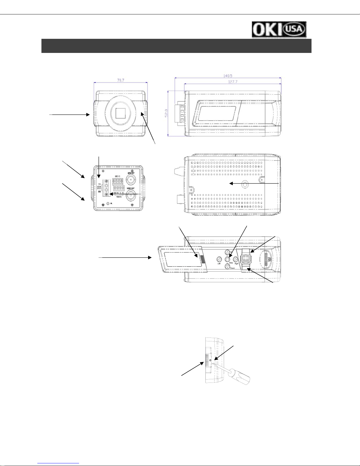
3. Name of Parts and Functions
A
K
J
I
DC12V/AC24 MODEL
H
L
B
F
G
E
C
A. C (CS) mount adapter if a CS mount lens is to be used, remove the C mount ring
B. Holder screw hole
Standard photographic pan-head screw size (1/4” – 20) Flange focal lock screw
C. Flange focal lock screw
D. Flange focal distance adjuster—adjust this ring when back focus adjustment is needed.
● Applicable for WDS-HDR1527DN & WDS-HDR1520
▲ Only Applicable for WDS-HDR1527DN
-3 -
D
Thumbwheel locking screw
and provided screwdriver
Back focus
thumbwheel
Page 4
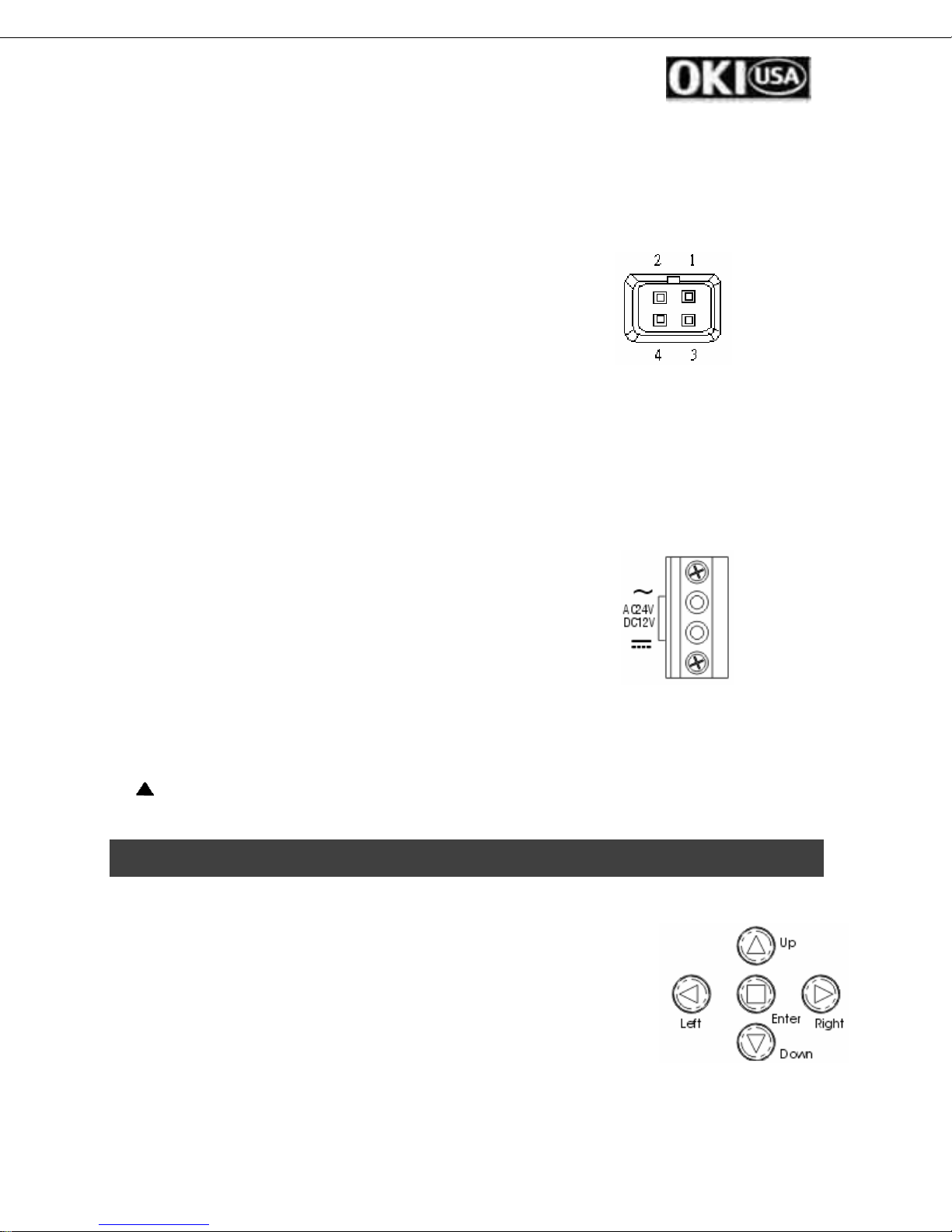
E. Auto iris lens connector (MINI JACK)
Use with accompanying auto iris lens control connector plug.
Auto iris lens has built-in EE amp. (VIDEO Type)
Set the lens selector to ”VD” position.
Connector cable leads
1.Red --- power 3.White --- video
2.NC 4.Black --- shielded
Auto iris lens without EE amp. (DC Type)
Set the lens selector to “DD” position.
Connector cable leads
1. Damping coil (-) 3. Driving coil (+)
2. Damping coil (+) 4. Driving coil (-)
F. Video output terminal (BNC)
This connector is used to connect with VIDEO IN connector of monitor.
G. On-Screen Display keypad
H. Slide out for control panel
I. Power pilot LED
J. DC12V / AC 24V Block Terminal
This terminal accepts DC 12V (Non-polarity) or AC 24V.
The other model: AC 85 ~ 265V.
K. OSD Remote control connector (MINI JACK)
L. The Device for sensing brightness level (for D/N function).
L. Only
Applicavle for WDS-HDR 1527DN
DC12V/AC24 MODEL
4. USER OSD SETTING
SETTING SWITCHES AND FUNCTIONS
1.UP button-This button is used to move the cursor upwards. Use
this button to select item.
2.LEFT button –This button is used to move the cursor left. Use to
select or adjust the parameters of the selected item.
3.RIGHT button-This button is used to move the cursor to the
right. Use to select or adjust the parameters of the selected item.
4.DOWN button-This button is used to move the cursor downwards. Use this button to
select item.
● Applicable for WDS-HDR1527DN & WDS-HDR1520
▲ Only Applicable for WDS-HDR1527DN
-4 -
Page 5
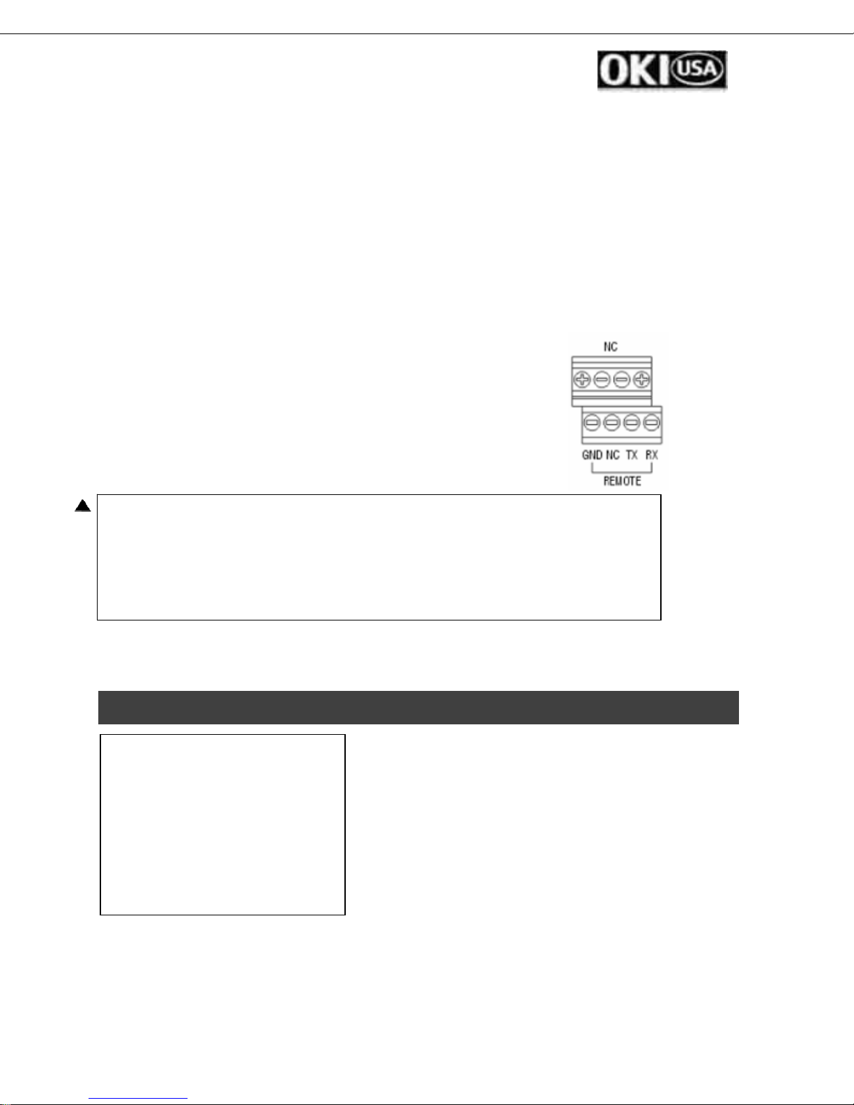
5.ENTER button-Press this button to display the setting menu, if the selected item has its
own menu; press this button to enter sub menu.
PC control
For window 95/98/ME/2000/XP
1. Insert the floppy into diskette drive
2. Execute OSD_CONT.EXE
3. A keypad icon will be displayed on screen
4. Use mouse to point the icon for on-screen-display setting.
RS-232 Connection Please refer to the Setup option
In the program window (com2 default)
1.RX pin----SD (D-sub 9) pin 3 from PC
2.TX pin----RD (D-sub 9) pin 2 from PC
3.NC
4.GND------GND (D-sub9) pin 5
1/O port The port can send or received signal by external device.
Select option mode by OSD D/N function
The camera can switch day or night by external device when it select
External mode.
And other mode can send signal to external device. Day (oV0, Night (+5)
▲ Only applicable for WDS-HDR1527DN
5. SETTING MENU AND FUNCTIONS
SETUP MENU
CAMERA ID OFF
SENSE UP OFF
LIGHT CNTL WD MODE
WHITE BAL ATW
PICTURE VIDEO
FOCUS ADJ
MISC
END INIT ↑ UNLOCK
1. Press the ENTER key to enter main menu.
2. Press UP/DOWN key to select the item for
adjustments.
3. Press ENTER key to enter the sub menu of
selected item.
4. Move cursor to END at the bottom of the screen
and press the ENTER to close the setup menu
and return to normal camera operation mode.
5. Move cursor to INIT and press ENTER to return all parameters to the factory default
settings. (Don’t press INIT unless it is necessary)
6. Move cursor to↑position and press ENTER key for menu position setting.
● Applicable for WDS-HDR1527DN & WDS-HDR1520
▲ Only Applicable for WDS-HDR1527DN
-5 -
Page 6

7. Move the cursor to UNLOCK and press the ENTER to LOCK the setup menu.
Note: If no button is pressed for 2 minutes while any setting menu displayed, all modified
UNLOCK PASSWORD
Press UP, DOWN, DOWN, RIGHT then ENTER key to unlock the menu.
data will be stored and camera will return to the normal camera picture mode.
6. Setting Procedure
6.1 Camera Identification Setting (CAMERA ID)
Move cursor to CAMERA ID then press ENTER key to enter ID sub menu
Blinking
CAMERA ID
0 1 2 3 4 5 6 7 8 9 :
A B C D E F G H I J K
L M N O P Q R S T U V
W X Y Z a b c d e f g
h i j k l m n o p q r
s t u v w x y z , .
□□□□□□□□□□□□
RET POSI ← →
Character Area
Editing Data Area
Command area
Move cursor to the character you wish to enter or modify by pressing UP, DOWN, RIGHT,
LEFT key. After selecting the character, by press ENTER key, selected character will
display on editing data area.
Repeat the step above until all characters are inputted or edited.
Move cursor to ← → to edit a specific character in editing data area.
Move the cursor to BLANK (between “z” and “,”) character position then press enter to
erase the character previously entered.
Move cursor to POSI, then press ENTER, the camera
ID will be displayed on screen.
Camera ID can be moved to desired position by
pressing UP, DOWN, RIGHT, LEFT key, then press ENTER
↑
← CAM 001 →
↓
to fix the ID position and return to previous menu.
● Applicable for WDS-HDR1527DN & WDS-HDR1520
▲ Only Applicable for WDS-HDR1527DN
-6 -
Page 7

6.2 Sense UPMove cursor to SENSE UP , Press LEFT T or RIGH key to select item,
SETUP MENU
CAMERA ID OFF
SENSE UP OFF
LIGHT CNTL WD MODE
WHITE BAL ATW
PICTURE VIDEO
MISC
END INIT ↑ UNLOCK
This function will start up and control electronic frame integration automatically.
6.3 Light Control
Move cursor to LIGHT CNTL then press ENTER key to enter sub menu
Mode sequence:
OFF 2X 4X 8X 16X
160 80X 40X 20X
The maximum sense up function for low bright,
It controls and offers the optimal brightness level by
increasing the number of stored fields of the CCD
in response to the brightness level.
SETUP MENU
CAMERA ID OFF
SENSE UP OFF
LIGHT CNTL WD MODE
WHITE BAL ATW
PICTURE VIDEO
MISC
END INIT ↑ UNLOCK
Press
ENTER to
sub menu
MODE INDOOR1
FLICKERLESS OFF
RETURN
WD MENU
Press RIGHT or LEFT key to select item, then press ENTER to enter Item sub menu
Mode sequence:
WD MODE NORMAL
6.3.1.1 WD mode setting
Press LEFT or RIGHT key to select item
Mode sequence:
INDOOR1 INDOOR2 INDOOR3 INDOOR4
ENGINEER OUTDOOR2 OUTDOOR1
The WD mode has 6 options:
• INDOOR1: Lobby or similar environments
• INDOOR2: Hallway or similar environments
• INDOOR3~4: Environments with large contrast
• OUTDOOR1: Camera near to the door surveillance for outside or similar
environments
● Applicable for WDS-HDR1527DN & WDS-HDR1520
▲ Only Applicable for WDS-HDR1527DN
-7 -
Page 8

• OUTDOOR2: Camera under strong light condition shooting to weak light
environments
• ENGINEER: This function is open for Engineer only.
6.3.1.2 FLICKERLESS (NTSC system only, PAL system off):
When the function is set to “ON”, the shutter speed 1/60 sec will become 1/100
sec to Flickerless. (NTSC system)
6.3.2. NORMAL mode setting
Move cursor to LIGHT CNTL and choose NORMAL then
press ENTER key to enter NORNAL mode sub menu.
6.3.2.1 NORMAL mode sub menu
• TYPE
Move cursor to TYPE and press LEFT or RIGHT to
change Auto Exposure TYPE
Mode sequence:
AES AUTO IRIS ME
Shutter speed of each mode:
AES mode: 1/50(1/60) to 1/100,000 sec.
AUTO IRIS mode: 1/50(1/60) sec
ME mode: 1/50(1/60) to 1/100,00 sec.
6.3.2.1.1 AUTO IRIS mode sub menu
Press ENTER key , AUTO IRIS menu will be displayed on
screen. Move cursor by UP/DOWN key to select
adjustment item.
SETUP MENU
CAMERA ID OFF
SENSE UP OFF
LIGHT CNTL NORMAL
WHITE BAL ATW
PICTURE VIDEO
MISC
END INIT ↑ UNLOCK
NORMAL MENU
TYPE AES
BLC OFF
AGC 00
E-ZOOM
RETURN
AUTO IRIS MENU
IRIS LEVEL 05
FLICKLESS OFF
RETURN
IRIS LEVEL: Press LEFT or RIGHT to adjust the level for auto-iris
Lens (for DC type). Ranging from 0 to 10.
FLICKERLESS (NTSC system only, PAL system off):
When function is set to “ON”, the shutter
speed 1/60 sec will become 1/100 sec to
Flickerless. (NTSC system)
● Applicable for WDS-HDR1527DN & WDS-HDR1520
▲ Only Applicable for WDS-HDR1527DN
-8 -
ME MENU
SHUTSPEED 1/50SEC
GAIN 01
RETURN
Page 9

6.3.2.1.2 ME mode sub menu
Press ENTER key to NORMAL menu, MANUAL
EXPOSURE menu will be displayed on screen.
PUSH TO LOCK MENU
PTL PUSH
RETURN
Move cursor by UP/DOWN key to select
adjustment item.
SHUTTER SPEED: 1/60(1/50), 1/120(1/100), 1/250, 1/500, 1/1,000,
1/2,000, 1/5,000, 1/10,000 sec.
Gain: You can increase or decrease the bright level.
• BLC:
Press LEFT or RIGHT key to turn Back Light
Compensation function ON/OFF
• AGC:
You can increase or decrease the bright level low light
NORMAL MENU
TYPE AES
BLC OFF
AGC 00
FLICKERSS OFF
E-ZOOM
RETURN
condition.
• E-ZOOM
Press ENTER key to display E-ZOOM sub menu.
6.3.2.1.2 E-ZOOM sub menu
Press LEFT or RIGHT key to change 3 type
E-ZOOM, press ENTER key back to previous
menu.
6.4 WHITE BALANCE
Move cursor to WHITE BAL then press ENTER key to enter
sub menu
Item sequence:
ATW→ PRESET → MANUAL → PTL Push To Lock →AT W
E-ZOOM 01 ← →
SETUP MENU
CAMERA ID OFF
SENSE UP OFF
LIGHT CNTL NORMAL
WHITE BAL ATW
PICTURE VIDEO
MISC
END INIT ↑ UNLOCK
● Applicable for WDS-HDR1527DN & WDS-HDR1520
▲ Only Applicable for WDS-HDR1527DN
-9 -
PRESET MENU
WB FIX INDOOR
3200K
RETURN
Page 10

1. ATW—Auto tracking white balance
2. Preset—fixed color temperature for Indoor →Outdoor→ Fluorescent→Indoor
3. PTL—Push to lock white balance
Press ENTER key the camera will process white balance. Character “PTL PUSH” will
then change to “PTL SETTING”, during the process. Please wait until the Character
change back to “PTL PUSH” to exit this menu.
MENU WHITE BAL MENU
R GAIN 15
B GAIN 12
RETURN
4. Manual—manual white balance
Change the value of R or B gain, to adjust desired white balance
6.5 PICTURE CONTROL
Menu item: VIDEO → GAMMA → APERTURE→ VIDEO
VIDEO MENU
1. Brightness level setting
Move cursor to BRIGHT position, while observing the color
RETURN
VIDEO MENU
BRIGHT 07
PEDESTAL 1.0 IRE
video monitor or waveform monitor / oscilloscope, press LEFT
or RIGHT key to adjust the brightness level.
2. Pedestal level setting
Move cursor to PESESTAL position, while observing the color video monitor or waveform
monitor / oscilloscope , press LEFT or RIGHT key to adjust the pedestal level.
APERTURE MENU
Press LEFT or RIGHT key to adjust aperture correction.
GAMMA MENU
APERTURE MENU
APERTURE 01
RETURN
1.There are 7-gamma curves, press LEFT or RIGHT key to
adjust gamma correction.
GAMMA MENU
Y GAMMA 02
RETURN
● Applicable for WDS-HDR1527DN & WDS-HDR1520
▲ Only Applicable for WDS-HDR1527DN
-10 -
Page 11

6.6 Day /Night Control ▲ only applicable for WDS-HDR1527DN
Move Cursor to D/N CNTL then press ENTER key to enter D/N MENU
SETUP MENU
CAMERA OFF
SENSE UP OFF
LIGHT CNTL NORMAL
WHITE BAL ATW
PICTURE VIDEO
D/N CNTL
FOCUS ADJ
MISC
END INIT ↑ UNLOCK
ENTER
D/N MENU
D/N TYPE LUX/DELAY
D Æ N Mode Normal
RETURN
Press RIGHT to LEFT key to select item, then Press the ENTER to enter
Item sub menu
Lux/Delay Æ SCHEDULE Æ EXTERNAL Æ DAY MODE Æ NIGHT
MODEÆ ENGINEER
▲6.6.1 D/N Type
1. LUX/ DELAY MENU
LUX/ DELAY MUNE
Press RIGHT or LEFT key to set the item.
LUX LEVEL LOW
LUX LEVEL- Sets the color to mono-
DELAY TIME 10 SEC
Chrome switching level. You can select
RETURN
LOW LVL, MID LVL, HI LVL.
DELAY TIME- Sets the detecting time. The color/ monochrome mode switches
If the brightness level change specified.
You can select 10 sec, 30sec or 60sec
2. SCHEDULE (D.N SWITCH TIME)
This function can set the time to change
the Day/ Night mode.
CHOICE D/N TYPE: Press ENTER key to Switch D
or N mode to conform to your setting Time.
LUX/ DELAY MUNE
LUX LEVEL LOW
DELAY TIME 10 SEC
RETURN
¤ If NÆ D time same with other camera will plus 1 minute by itself.
3. EXTERNAL
This function allow use external device to
Control camera switch to Night mode by
HI(+5V) potential or LOW (0V) potential.
¤ Function 1~3 will action when back to first menu
EXTERNAL D Æ N MENU
INPUT SIGNAL HI
RETURE
(SETUP MENU)
● Applicable for WDS-HDR1527DN & WDS-HDR1520
▲ Only Applicable for WDS-HDR1527DN
-11 -
Page 12

4. DAY MODE 4. DAY MODE
Switch to DAY mode. Switch to DAY mode.
5. NIGHT MODE 5. NIGHT MODE
Switch to NIGHT mode. Switch to NIGHT mode.
6. ENGINEER MODE 6. ENGINEER MODE
This mode for engineer only. This mode for engineer only.
▲ 6.62 DÆN MODE ▲ 6.62 DÆN MODE
This item will switch to WD mode or Normal Mode when Night Mode. This item will switch to WD mode or Normal Mode when Night Mode.
▲ Only applicable for WDS-HDR1527 DN ▲ Only applicable for WDS-HDR1527 DN
6.7 FOCUS ADJ 6.7 FOCUS ADJ
Move cursor to FOCUS ADJ then press ENTER key to enter FOCUS ADJ MENU Move cursor to FOCUS ADJ then press ENTER key to enter FOCUS ADJ MENU
CAMERA ID OFF
SENSE UP OFF
END INIT ↑ UNLOCK
SETUP MENU
LIGHT CNTL NORMAL
WHITE BAL ATW
PICTURE VIDEO
D/N CNTL
FOCUS ADJ
MISC
ENTER
Please adj focus Please adj focus
Press ENTER to exit
Press ENTER to exit
This function help user to adjustment suitable position for lens focus. This function help user to adjustment suitable position for lens focus.
When Completed the focus adjust press the ENTER key back to Setup Menu. When Completed the focus adjust press the ENTER key back to Setup Menu.
6.8 MISC 6.8 MISC
This function is to adjust the camera’s synchronization and lens applications. Move cursor to
This function is to adjust the camera’s synchronization and lens applications. Move cursor to
MISC and press Enter.
MISC and press Enter
.
1. EXTSYNC 1. EXTSYNC
Press LEFT or RIGHT key to select the type of
Press LEFT or RIGHT key to select the type of
camera’s synchronization, then press ENTER key to
camera’s synchronization, then press ENTER key to
enter external sync phase adjusting menu.
enter external sync phase adjusting menu.
Align sync phase by press LEFT or RIGHT key. Align sync phase by press LEFT or RIGHT key.
2. AUTO IRIS 2. AUTO IRIS
Press LEFT or RIGHT key to select the type of Press LEFT or RIGHT key to select the type of
Auto-iris lens: DC lens / Video lens. Auto-iris lens: DC lens / Video lens.
3. H/V MIRROR 3. H/V MIRROR
Press LEFT or RIGHT to Left/right reversal (H) or
Press LEFT or RIGHT to Left/right reversal (H) or
Top/bottom reversal (V) or rotates the image 180
Top/bottom reversal (V) or rotates the image 180
degrees (H/V).
degrees (H/V).
▲ Only applicable for WDS-HDR1527DN
MISC MENU
EXT SYNC INT
AUTO IRIS DC LENS
H/V MIRROR OFF
MASK
SYSTEM HOUR: 08
MIN: OO
SYSTEM TIME: DISPLAY
RETURN
● WDS-HDR1520
MISC MENU
EXT SYNC INT
AUTO IRIS DC LENS
H/V MIRROR OFF
MASK
WINKER OFF
RETURN
● Applicable for WDS-HDR1527DN & WDS-HDR1520
▲ Only Applicable for WDS-HDR1527DN
-12 -
Page 13

7. SPECIFICATIONS
Image device 1/3” interline transfer Super HAD CCD
Signal system PAL or NTSC standard
Picture elements PAL: 795(H) x 596(V), NTSC: 811(H) x 508(V)
Scanning system PAL: 625 lines, NTSC: 525 lines, 2:1 interlace
Sync system DC Internal/ AC Line lock sync
Horizontal resolution Color: 520 TV Lines BW: 570 TV-Line ▲ WDS-HDR 1527DN
Color: 520 TV Lines
Minimum illumination: 0.5Lux at F1.2 (30 IRE, AGC 36dB)
Aperture correction V aperture-gain adjustable
Gain AGC 0- 36dB
S/N ratio Better than 50dB
Contrast level 400:1
Wide dynamic range 52dB
Frame integration 2X~160X
Masking 8 areas ON/OFF, color, position, size adjustable.
E-ZOOM 3 types E-ZOOM (Normal mode only)
Mirror Horizontal, Vertical, 180°
Auto exposure system 1. AES mode (auto) : 1/50(1/60) - 1/100,000 sec.
2. Auto iris mode : 1/50(1/60) sec.
Manual exposure system Shutter speed:
1/50(1/60), 1/120, 1/250, 1/500, 1/1000, 1/2000, 1/5000, 1/10000 sec.
Gain: AGC 0~36dB
White balance ATW : Max 2500° K- 9500° K
Push to lock : gain memory
PRESET : Indoor mode 3200°K, Outdoor mode 6300° K,
fluorescent mode 4200°K
Manual mode R gain, B gain adjustable
Day & Night 1, Auto detect: D/N switch illumination level, Delay times
2, D/N by Schedule: Day to Night to day time
3, D/N by External: Hi (DC 5 V) or Low (DC 0V) switch to night mode
4, Day mode
5, Night Mode
▲ Only for 1527 DN
Video output signal Composite (BNC): 1.0 Vp-p at 75Ω loads
Gamma correction Y gamma curve selectable
OSD presentable function
1. Camera ID: up to 12 characters alphanumeric, position
2. Sense UP: 2X ~160X
3. Light control: WD mode: 6 preset setting
NORMAL mode: AES, AUTO IRIS, ME, BLC ON/OFF, AGC 0~15 (36dB),
FLICKERLESS (NTSC only), E-ZOOM
4. White balance: ATW, Preset, Manual, PTL
5. Sync system selection, phase adjustment
6. Picture Brightness, gamma, aperture correction
7. Miscellaneous: Lens selects, IRIS Level, Mirror, Mask, Winker
8. OSD menu lock
● WDS-HDR1520
● Applicable for WDS-HDR1527DN & WDS-HDR1520
▲ Only Applicable for WDS-HDR1527DN
-13 -
Page 14

Auto iris lens Accepts video or DC drive iris lens
Lens mount C & CS mount
Operating temperature -10°C to 50°C
Power source DC 12V
AC 24V /DC 12V
AC 85 ~ 265 V
Power consumption: ▲5.5 W (DC type)
▲5.8 W (AC type) WDS-HDR1527DN
● 4.2(DC type)
● 4.5(AC type) WDS-HDR1520
Dimensions (W x H x D): 71 x 52 x 128 mm
Memorandums
● Applicable for WDS-HDR1527DN & WDS-HDR1520
▲ Only Applicable for WDS-HDR1527DN
-14 -
Page 15

 Loading...