

Page 1

Oki Voice Over IP Telephony Adapter
Installation Guide
Version 1.2
Oki Electric Industry Co., Ltd.
Page 2

Safety Warning!
This document contains information regarding the safe use of the Oki
VoIP-TA unit. Carefully observe and comply with all safety precautions.
Page 3

© 1999-2000, Oki Electric Industry Co., Ltd. All rights reserved.
The VoIP-TA Internet Telephony Adapter and the Maintenance Console
Software are products of Oki Electric Industry Co. Ltd.
The right to reproduce this manual and/or the Maintenance Console Software is
restricted by the Copyright Act.
No part of this document may be copied, reproduced, stored on a retrieval
system, or transmitted in any form or by any means, electronic, mechanical,
photocopying, recording, or otherwise, in whole or in part, without the written
permission of Oki Electric Industry Co. Ltd.
Information in this document is subject to change without notice.
The contents of this document and the Maintenance Console Software have
been prepared with the utmost care. However, if you notice an irregularity,
please contact an authorized sales agent.
Oki Electric Industry Co. Ltd., assumes no responsibility with regard to
consequences resulting from the use of the Maintenance Console Software and/or
the contents and interpretation of the information contained in this manual.
Ethernet is a registered trademark of Xerox Corporation.
MS-DOS and Windows are registered trademarks of Microsoft Corporation.
Other companies and product names mentioned in this manual my be the
trademarks or the registered trademarks of their respective companies. Oki
Electric Industry Co. Ltd., neither endorses or recommends third-party
products mentioned herein nor assumes responsibility with regard to the use
or performance of these products.
ii
Page 4

Contents
Important Safety Instructions v
Introduction vii
I Outline 1
The VoIP-TA 1
Features 1
Front Panel 2
LEDs 2
Back Panel 3
Connectors 3
II Installation 5
Connections 5
Cautions 7
III Placing Calls 8
Via an IP Network 8
General Operation 8
Services 9
Third party incoming call during another call 9
End-to-end service using DTMF signaling 10
Call transfer during a telephone Call 10
Absent Service 12
Details of Services 13
Using both a PSTN line and the IP network 13
Line selection 13
Third party incoming call during another call 13
Identification of incoming call 15
Power failure switching 15
Using the IP network only 16
Third party incoming call during another call 16
Translating IP Address for VoIP 16
Setting IP Address 16
IV Setup 17
Maintenance Console Software Requirements 17
Installing the Maintenance Console Software 17
Maintenance Console Software Compatibility 17
Functions of the Maintenance Console Software 18
Contents
iii
Page 5

Data Setup Procedure 18
Activating and Deactivating the Software’s Functions 19
Changing Modes and Setup Condtions 21
Changing to the setup mode 21
Changing setup conditions 22
Saving all setup conditions in a file 23
Reading information from the file 24
Setup (VoIP-TA setting) Window 25
Basic settings for the PSTN line 25
Select outgoing destination 26
Detailed settings for the PSTN line 29
Network settings 30
Network Address Translation (NAT) 32
Gatekeeper Settings 34
Detailed gatekeeper settings 35
Address Table 36
Sorting the list using each row as a key
Address table display editing 36
Details 38
Voice settings 39
Voice codec setting and bandwidth used 40
FAX setting 41
SLIC setting 42
(Sort with key) 36
V Maintenance 43
Functions of the Maintenance Console Software 43
Verifying the Software Version Information 43
Checking the Operation Status of the VoIP-TA 44
Explanation of the displayed information 45
Updating Unit Programs 46
Changing the Password 47
VI Troubleshooting 48
VII Specifications 49
Important Equipment Information 50
Warranty and Service 51
Oki Service Offices 52
Contents
iv
Page 6

Important Safety Instructions
When handling or using the VoIP-TA unit, the following safety precautions should
be observed to prevent injury and/or damage to the unit. Use of this equipment in
a manner other than that specified in this and other VoIP-TA documents will void
the product warranty and may result in damage, serious injury or death.
WARNING Incorrect use by neglecting the following instructions
may cause fire, electric shock, unit failure, resulting in
damage, serious injury or death.
• Do not connect a commercial power supply circuit, analogue, digital
(ISDN) or PBX digital telephone line to the LAN or PC port.
• Do not use with power supply voltages other than those specified.
• Do not insert or drop metal objects into any of the openings.
• Do not disassemble or modify this product in any way.
• Do not place any vases, cups, cosmetics, chemicals, pots or any other
containers containing liquids or small metal objects, near the product.
Spillages into the product may cause fire, electric shock or unit failure.
• Do not try to connect or disconnect the power plug with wet hands.
• Insert the power plug fully and securely into the power outlet. To avoid
electric shock, do not use a plug that exposes the terminals when
inserted.
• Avoid star connections as fire or overheating may result.
• Do not put heavy objects on the AC adapter cord or expose it to
excessive heat.
• Do not pull the cord or allow it to overheat as it may be damaged and
could cause fire or electric shock.
• If lightning strikes a neighboring area, stop operating the product by
disconnecting the AC plug (by grasping the power plug, not the cord)
from the power supply outlet.
• Always ground the product properly.
Important Safety Instructions
v
Page 7

• Do not use AC adapters other than those specified or supplied.
• If liquid enters the unit, immediately disconnect the power plug (by
grasping the power plug, not the cord) from the power outlet and
contact an authorized sales agent or service provider. Continued use
may result in fire or electric shock.
• If smoke or fumes are emitted from the unit, immediately disconnect
the AC plug (by grasping the power plug, not the cord). When smoke
emissions cease, contact a sales agent or service office for repair.
Continued use may cause fire, electric shock or unit failure.
• Use only authorized sales agents or service offices for internal
inspection or repair.
CAUTION Incorrect use by neglecting the following instructions
may cause fire, electric shock, unit failure resulting in
injury or damage.
• Avoid oily, humid or dusty locations, such as on a kitchen table or near
a humidifier.
• Do not place the unit on unstable or inclined surfaces as the unit may fall.
• Avoid locations exposed to direct sunlight or moisture as internal
overheating may occur causing fire or unit failure.
• Wipe away with a dry cloth any water droplets that may be on the
surface of the unit. Water intrusion may cause fire or unit failure.
• Do not cover up the vent holes of the VoIP-TA. If covered, internal
overheating may result causing fire or unit failure.
• Do not unplug the AC power plug by pulling on the cord. Always grasp
the plug portion when disconnecting the AC power plug.
• Disconnect the AC power cord and other connectors when moving the
VoIP-TA.
• For safety, disconnect the AC plug from the power supply outlet (by
grasping the power plug, not the cord) before starting maintenance.
Important Safety Instructions
vi
Page 8

Introduction
Welcome to the world of Oki Internet telephony…
The Oki voice over IP (Internet Protocol) telephony adapter, VoIP-TA, is a
self-contained H.323 version 2 compliant communications device that
allows organizations to route both voice and facsimile communications
over any TCP/IP network.
The VoIP-TA is designed to provide a service that is virtually
indistinguishable from that of conventional telephone and facsimile
services.
Use this guide to familiarize yourself with the VoIP-TA. Should you need
to handle the equipment, pay special attention to the procedures and
safety precautions contained in this guide.
vii
Introduction
Page 9
I
I
Outline
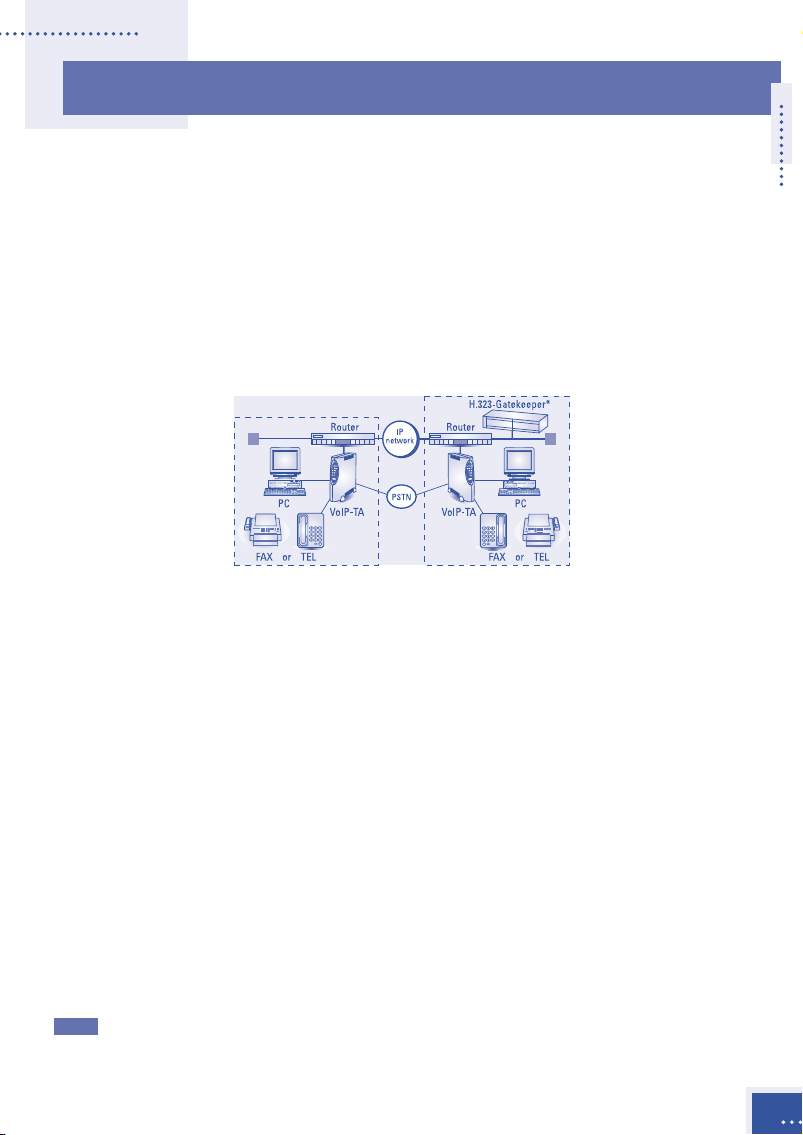
The VoIP-TA
The VoIP-TA is a one-channel Internet telephony adapter that provides
Internet telephony services conforming to industry standard H.323
version 2 specifications. It can be connected to a conventional analogue
telephone or G3 facsimile machine.
Once installed, VoIP-TA units use the Internet Protocol (IP) network to
bridge the distance between units at a fraction of the cost associated with
conventional telephony methods.
* Gatekeeper is necessary when more than 100 IP addresses are to be used.
Features
• Compact size and one-channel Internet telephony adapter.
• Automatic telephone routing by specified telephone numbers.
• A PC connection port is provided however, the VoIP-TA cannot
communicate with a PC connected to the PC port.
• Smooth and natural telephone calls by optimizing the voice buffer.
• Supports Dynamic Host Configuration Protocol (DHCP manual
allocation) for local IP addresses.
• Conforms to the ITU-T recommended H.323 version 2 specifications.
• Supplies real-time Internet facsimile communication that conforms to
the ITU-T recommended T.38.
• Uses high quality voice compression technology.
Conforms to ITU-T G.729A (8 kbps), G.723.1 (5.3/6.3 kbps), and G.711
(µ-law/A-law). [Automatic selection or fixed]
The Public Switched Telephone Network (PSTN) is supported by VoIP-TA version
Note
1.2 and later. The version number is clearly marked on the bottom of the unit.To
avoid incorrect use contact your authorized sales agent or service office if in doubt.
Outline
1
Page 10
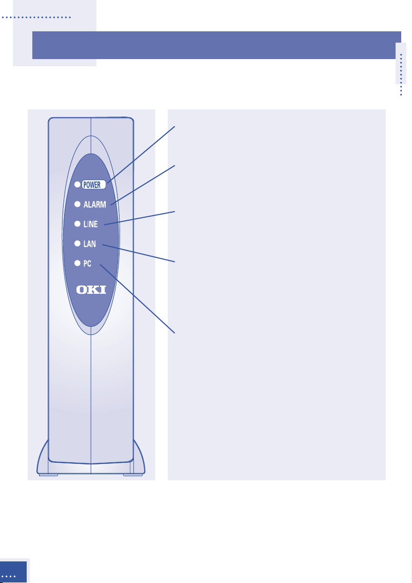
Front Panel
LEDs
POWER Indicates power ON when lit.
Green lamp.
ALARM Indicates alarmed condition
detected in unit when lit.
Red lamp (see table 1 page 4).
LINE Indicates PSTN line is used
during operation when lit.
Green lamp.
LAN Indicates LAN link is
established and operating
normally when lit . When
blinking, data is being sent.
Green lamp.
PC Indicates link is established
and operating normally when
lit. When blinking, data is
being received.
Green lamp.
Outline
2
Page 11
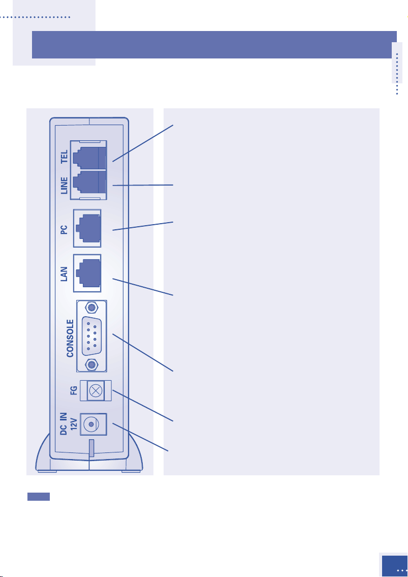
Back Panel
Connectors
TEL Connects a conventional
analogue telephone or G3
facsimile machine. Dial signal:
DTMF signaling only.
LINE Connects to an analogue
public telephone line.
PC* Connects to a PC via a straight
cable (category 3 or higher).
Not for Maintenance Console
Software. Use category 5 for
100BASE-TX.
LAN* Connects to LAN via a cross
cable (category 3 or higher).
Use a straight cable for HUB
connection. Use category 5 for
100BASE-TX.
CONSOLE Connects to a PC (serial port)
for data setup. Use an RS232C
connector cable (straight).
FG Terminal strip for frame
ground.
DC IN 12V Connects an AC adapter.
The communication performances of the LAN and PC ports are always the same and
*
VoIP-TA conforms to the lower of the two. When either the PC or LAN port is 10
BASE-T, both ports are set to 10 BASE-T communication. If a PC is connected to the
PC port during a call, the call may be interrupted for approximately one second.
Please avoid such usage.
Outline
3
Page 12

Table 1
Mode ALARM-LED LINE-LED Status
Initialization Blinks OFF With gatekeeper:
(1 sec. The system will wait for
intervals) LAN link to be established while
gatekeeper registers the VoIP-TA.
Without gatekeeper:
The system will wait for a LAN link to
be established.
Operation OFF OFF Standby
OFF ON The telephone line is busy.
OFF Blinks (1 sec. When using both IP and PSTN:
intervals) The PSTN is on hold during VoIP calls.
When using IP network only:
The absent service is setting up.
Blinks (0.5 sec. The handset is off the hook and the
intervals)
Setup Blinks (0.2 sec. Blinks (0.2 sec. Normal operation is not available in
intervals) intervals) the Setup mode.
OFF howler tone has
already stopped.
Installation Blinks (0.2 sec. Blinks (1 sec. Normal operation is not available in
intervals) intervals) the
Outline
4
Install mode. The LED lamp may
blink irregularly during the program
installation.
Page 13
II
II
II
II
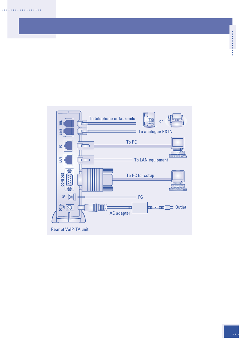
Connections
Installation
Place the main unit in a vertical position as placing it horizontally could
shorten the life of the unit.
The following illustration shows where equipment should be connected
to the ports at the rear of the VoIP-TA unit.
Analogue telephone or G3 facsimile equipment
Connect an analogue telephone or G3 facsimile machine to the TEL
connector of the VoIP-TA unit via a telephone cord.
To make facsimile connections, the other end terminal equipment should
be compliant with the ITU-T T.38 standard.
Analogue PSTN
Connect an analogue PSTN line to the LINE port at the rear of the VoIP-TA
unit via a telephone cord.
Installation
5
Page 14

Personal computer (PC)
Connect a PC connector to the PC port at the back of the VoIP-TA unit
using an unshielded twisted pair (UTP) straight cable
If both a PC and LAN are to use 100BASE-TX communications, use
category 5 [max. 100m].
It is recommended that only one PC is connected to avoid voice deterioration.
Note
(categories 3 to 5).
LAN
Connect the LAN connector to the LAN port at the back of the
VoIP-TA unit via a cross cable (UTP categories 3 to 5). If connecting to a
hub, use a straight cable.
If the LAN is connected by 100BASE-TX and the PC is connected by
100BASE-TX, or if the PC is not connected, use a category 5 cable
[max. 100 m].
CONSOLE (setting up the VoIP-TA with a PC)
Connect the PC for setup on the VoIP-TA by using the serial cable RS232C (9 pin – 9 pin straight) to the CONSOLE port.
FG (grounding)
After connecting the frame ground (FG) cable to the FG port at the back
of the VoIP-TA unit, connect the other end to a ground terminal in the
house or ground it separately.
6
Power source
Connect the supplied AC adapter to the DC IN 12V port at the back of the
VoIP-TA unit. Connect the attached AC adapter to a power outlet.
Installation
Page 15

Cautions
During installation
• All cables used to connect the equipment must be accessories of the
equipment or suitable to fit the equipment.
• Make sure the AC power plug is disconnected from the power outlet
when connecting the FG cable to the unit.
• When an exchange machine, such as PBX or EKTS is connected to the
TEL port of VoIP-TA, the sound quality may deteriorate. Only one
exchange machine should therefore be relayed between the VoIP-TA unit
and telephones.
• Interference noise may occur during telephone calls in areas that receive
strong radio waves, such as near a broadcasting station or CB radio
transmission. If calls are affected in this way, consult your authorized
sales agent or service office.
• Do not install the VoIP-TA unit near equipment that generates
magnetism or radio waves such as TV sets, radios, radio machines,
microwave ovens, or inverter-type fluorescent lamps, as this may cause
the unit to malfunction.
During use
• Do not subject the unit to strong impact, such as dropping the unit.
• Do not force cables to connect or disconnect as this may result in faults.
The connector and port should join with reasonable ease.
• When cleaning the exterior of the VoIP-TA, turn it off and disconnect the
unit (by pulling the power plug, not the cord), wipe it with a water damp
cloth and wipe it dry with a soft dry cloth. Do not use volatile thinner,
alcohol or a silicon cleaner under any circumstances as it may result in
damage, discoloration or deformation.
Installation
7
Page 16

III
III
Placing Calls
Via an IP Network
Placing and receiving calls with the VoIP-TA unit are usually quite simple
and performed in the same way as conventional telephone networks. In
some cases however, the phone numbers to be used, may differ slightly
from the ones you used previously.
General Operation
Outgoing calls
Use a telephone that generates a Dual Tone Multiple Frequency (DTMF)
signal. Pick up the handset and dial a remote party’s telephone number.
Incoming call response
An incoming tone will be emitted from the telephone.
Disconnection
A telephone call can be disconnected by hanging up the handset onto the
telephone receiver.
8
Placing Calls
Page 17
Services
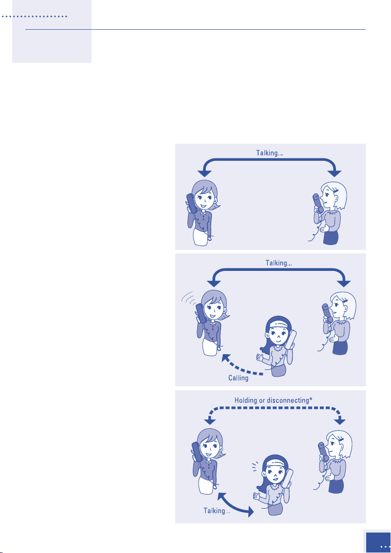
Third party incoming call during another call
You can respond to a third party’s incoming call while you are on
another call.
• A second party
telephone call.
• If a third party calls, a
notification tone is sent
to your telephone.
• You may speak to a
third party by hooking.
* The operation varies
depending on the data
settings. See Details of
Services page 13,
Placing Calls
9
Page 18
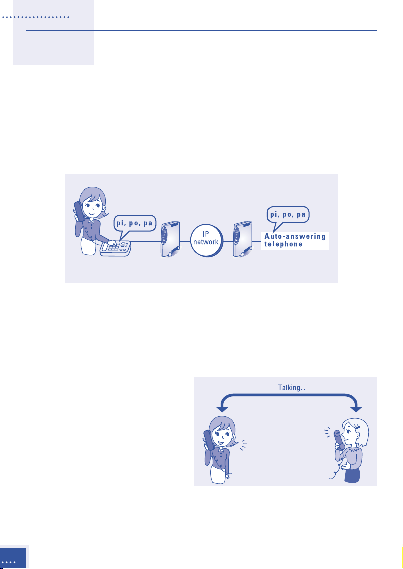
End-to-end service using DTMF signaling
DTMF signaling can be used via the IP network for answering machines,
etc. To use this service,
be turned off.
• Making a telephone call
Facsimile transmission using the VoIP line, must
Call transfer during a telephone call
You can transfer a call during a telephone call. To use this service, Use
PSTN line must be turned off.
10
• During a telephone call
Placing Calls
Page 19

• Put the other party on
hold by hooking, and
dial a transfer
destination number.
• You may then speak to
the party at the
transfer destination.
• When you hang up the
handset again the call
will be automatically
transferred to the
destination.
Placing Calls
11
Page 20

Absent service
If the absent service is registered, an incoming call is transferred to a
registered destination. The transferred call will not be transferred any
further.
To use this service,
Use PSTN line must be turned off.
How to register the absent service
Pick up the handset, dial “***11” and the
“destination number to be transferred” and
hang up the handset. When the service is set,
the LINE-LED lamp will blink.
How to cancel the absent service
Pick up the handset, dial “***12,” and hang up
the handset. When the service is cancelled, the
LINE-LED lamp will go off.
12
Placing Calls
Page 21

Details of Services
There are two ways to use the VoIP-TA unit; using both a PSTN line and
the IP network or using only the IP network. These services are
determined by the data setup.
Using both a PSTN line and the IP network
Line selection
The selection of a PSTN line or IP network is specified by the first digit of
the phone number set by the Maintenance Console Software.
Third party incoming call during another call
For PSTN line receiving services using hookflash (hooking) from regional
telephone service company
• Response to
incoming calls
from a PSTN
line during a
telephone call
using the IP
network.
• Response to an
incoming call
from the IP
network during
a telephone
call using a
PSTN line.
Placing Calls
13
Page 22

• Incoming
operation from
the IP network
during a
telephone call
using the IP
network.
For PSTN line not receiving services using hookflash (hooking)
• Response to an
incoming call
from a PSTN
line during a
telephone call
using the IP
network.
• Response to an
incoming call
from the IP
network during
a telephone
call using a
PSTN line.
14
Placing Calls
Page 23

• Incoming
operation from
the IP network
during a
telephone call
using the IP
network.
Identification of incoming call
An incoming call can be identified by setting a ringing time from IP
network and from a public telephone line separately.
Example
Power failure switching
If a power failure occurs, the telephone is directly connected to a PSTN
line.
CAUTION When supplying power to a telephone set during
power failure, the polarity may be reversed
depending on a line port connection mode.
Placing Calls
15
Page 24

Using the IP network only
Third party incoming call during another call
• Incoming call
during an existing
telephone call.
Translating IP Address for VoIP
Without gatekeeper Uses the built-in address table (max. number of
registered addresses: 100).
With gatekeeper Translates IP address with gatekeeper.
Setting IP Address
The initial value is not set at the shipment time. Set the IP address using
the Maintenance Console Software or obtain it from the DHCP server.
When getting IP addresses from the DHCP server, the IP address should
always be a fixed address and allocated manually.
16
Placing Calls
Page 25

IV
IV
Setup
The VoIP-TA is set up by using the Maintenance Console Software. The
Maintenance Console Software, installed in a PC, is used to communicate
with the VoIP-TA in remote mode via a LAN interface or in local mode via
a RS232C interface. When connecting to the VoIP-TA using the remote
mode via a LAN interface, all network settings such as the assignment of
IP addresses must be already completed.
Maintenance Console Software Requirements
Description Quantity
Maintenance Console Software setup disk (CD-ROM). 1
A PC for installing the Maintenance Console Software.
• An operating system, such as Windows
Windows NT®4.0, must already be installed in the PC.*
• The PC must be equipped with a S-VGA (Super Video Graphics Array). 1
A LAN cable (UTP, category 3 or 5) or a RS232C cable. 1
*Note
Windows®and Windows NT®are registered trademarks of Microsoft
Corporation in the U.S.A. and other countries.
®
98, Windows®95, or
Installing the Maintenance Console Software
Before installing the Maintenance Console Software in a PC, be sure to
close and quit all software and programs running on the PC.
• Insert the CD-ROM into the PC’s CD-ROM drive and execute the Setup
file located on the disk (when reinstalling the software, be sure to
uninstall the previously installed Maintenance Console Software first).
• Follow the prompts appearing on the screen and restart the PC when
the installation has been completed. You may now use the
Maintenance Console Software.
Maintenance Console Software Compatibility
The compatibility relationship between the VoIP-TA unit software and
Maintenance Console Software versions is described in the table below.
VoIP-TA unit Operation software Maintenance Console Software version
V1.1 02.** V1.0
V1.2 04.00 V1.2
Setup
17
Page 26

Functions of the Maintenance Console Software
The functions of the Maintenance Console Software vary according to the
mode in which the VoIP-TA unit has been set.
Mode Function Notes
Operation mode Perform usual operation.
Display the current setup conditions.
Setup mode Change the current setup conditions. For details on how to change the
Change a password. password, see Chapter V, page 48.
Installation mode Update programs of VoIP-TA. See Chapter V, page 47.
Not normally used.
In addition to these functions, the Maintenance Console Software has status
display and version display functions (see Chapter V, page 44).
Data Setup Procedure
• Connect the PC (with the Maintenance Console Software installed) to
the CONSOLE port of the VoIP-TA unit via a RS232C cable.
Examples of connection of the Maintenance Console Software running
on a PC are shown below:
Connection via a RS232C cable Direct connection via a LAN cable
18
Setup
Page 27

Connection via a hub
• Switch the VoIP-TA to Setup mode.
• Change the setup conditions.
• Switch the VoIP-TA to Operation mode.
Activating and Deactivating the Software’s Functions
Start the Maintenance Console Software installed on the PC to set up the
VoIP-TA.
Activating and deactivating operation flow
Setup
19
Page 28

The procedure for activating the Maintenance Console Software for the
VoIP-TA unit is described in step-by-step instructions starting with the
software through to connection with the VoIP-TA unit’s functions.
• Click on Start on the task bar, bring the cursor pointer on Program, and
then click on VoIP-TA console.
• The Initial window will
appear.
• Click on Run (R)on the
menu bar.
• When the pull-down menu appears, select Connect.
• The New connection
window will appear.
• Select a connection
mode.
20
LAN connection:
Remote connection via a LAN interface.
Specify the IP address of the VoIP-TA in the Host entry area.
Serial connection:
Local and direct connection via a RS232C interface.
Specify the COM port for the PC to be connected to the VoIP-TA.
Start connection by clicking on the OK button.
Setup
Page 29

• For the LAN connection, a
password entry prompt will
appear. Enter the password, and
click on the
OK button. The
product has been shipped with
“TA” set as the default password.
• When the connection settings are
completed, the
Main
window is displayed.
When the Data setting and
Status buttons become
active, the connection is
established.
Changing Modes and Setup Conditions
The mode of VoIP-TA can be switched by using the Maintenance Console
Software.
To change the current setup conditions, switch the VoIP-TA to the setup
mode (it is not necessary to switch the VoIP-TA to the setup mode if you
only want to display the setup conditions).
Changing to the Setup mode
• Click on Mode (M) on the
menu bar of the Main window
and select the Change mode
on the pull-down menu.
• The
• Select the
• Changing VoIP-TA to other modes is performed in the same way.
The VoIP-TA mode will change although it may take a little time for the mode to
*
be changed.
Mode change prompt is
displayed.
Setup mode on the
Mode pull-down menu and
click the OK button.
Setup
21
Page 30

Changing setup conditions
• Once the setup mode has
been changed, click the
Data setting button on the
Main window.
• The setup (VoIP-TA
setting)
Click the tabs on the window to display the desired current status.
Change the items displayed on the window, as necessary.
A detailed explanation of each window is provided in Setup (
setting) window (see page 24).
• Once the necessary changes
have been made on the setup
window, they can be set by
clicking the OK button.
The changed items can be saved
*
on the PC as a file by clicking on
the Save button (see page 23).
window will appear.
VoIP-TA
22
The file containing the saved
*
changes of the setup can be
retrieved by clicking on the Read
from file button (see page 23).
• To set the VoIP-TA to the
operation mode, click on Mode (M) on the menu bar of the main
window and select Change mode in the pull-down menu. The Mode
change window will be displayed. Select Operation mode on the pulldown menu and click the OK button. After the mode change the new
setting will become effective.
Setup
Page 31

Saving all setup conditions in a file
The default setting is set to save all setup conditions within a file. This
setting can be changed by clicking on the
window and displaying the Saved-information select window.
• Activate or deactivate the check
mark for Address table or Other set
values as required. If either or
both items are unchecked then no
record of that setting will be saved
in a file.
• To save, click the OK button.
The File saving window will
be displayed. Specify a name
for the file (in which the
setup conditions are to be
saved), by entering it in the
space next to File name.
Save button on the setup
Setup
23
Page 32

Reading information
from the file
• To read information
contained in the saved
file, click on the
Read
from file button in the
setup window. The File
selection window will
be displayed.
• Select the appropriate
file, and click the Open button.
The Read-information select window will be displayed.
The default setting reads all the setup conditions within a file. This
setting can be changed by activating or deactivating the Address table
or Other set values as required.
• When the settings have
been made, click the OK
button.
24
Setup
Page 33

Setup (VoIP-TA setting) Window
Basic settings for the
PSTN line
Item Descriptions Default
Use PSTN line To connect VoIP-TA to a PSTN line, check this item. Not used
Facsimile To use a facsimile, check this item (please note that when Used
transmission a facsimile is in use, the DTMF signaling end-to-end service
using VoIP-TA via VoIP communication is not available.)
Select Available when
outgoing (PSTN or VoIP) can be selected by the outgoing destination
destination number. Clicking this button displays the setup screen (see
Select outgoing destination below).
Hookflash This setting is used only when services using Hookflash None
(hooking) is being provided by a regional telephone company.
Detail setting Sets the telephone line details. The
is displayed when this button is clicked (see Detailed setting
for PSTN line page 29).
Use PSTN line is selected. An outgoing line
PSTN line details window
Default values, set at the time of product shipping, are displayed when
the Restore default button is clicked.
Setup
25
Page 34

Select outgoing destination
• Selecting an outgoing
destination is available only
when Use PSTN line is
selected. If it is not selected,
all outgoing calls are via the
VoIP line, without neglecting
the first digit of the phone
number.
Item Description Default
Select • Select Use PSTN line, Use VoIP line or Unavailable to dial 0 PSTN line
outgoing the first digit of an outgoing destination telephone number. 1 PSTN line
destination • Selection can also be made to Neglect the first digit or not 2 VoIP line
to do so at the same time. 3 VoIP line
• Select Use PSTN line to use the PSTN line for outgoing calls. 4 VoIP line
• Selecting Unavailable to dial will not allow any outgoing calls. 5 VoIP line
• Select Use VoIP line to use the VoIP line for outgoing calls. 6 VoIP line
• When the selection is made to neglect the first digit, the 7 VoIP line
first digit is not recognized as a part of the outgoing 8 VoIP line
destination telephone number. 9 VoIP line
• An asterisk (*) cannot be used as a part of an outgoing # VoIP line
telephone number. Neglect first
digit is not
selected.
26
Default values, set at the time of product shipping, are displayed when
the Restore default button is clicked.
Setup
Page 35

Example
Software settings and resulting VoIP-TA operations for outgoing
destinations are provided below as well as the information of outgoing
destinations and the IP address table of the VoIP-TA:
1st Outgoing Neglect
digit destination 1st digit
0 Use PSTN line —
1 Use PSTN —
2 Use PSTN Selected
3 Use PSTN Selected
4 Unavailable to dial —
5 Unavailable to dial —
6 Unavailable to dial —
7 Use VoIP line —
8 Use VoIP line —
9 Use VoIP line Selected
# Use VoIPline Selected
Dailing IP address
number
789 111.222.333.789
890 111.222.333.890
901 111.222.333.901
012 111.222.333.012
123 111.222.333.123
234 111.222.333.234
345 111.222.333.345
456 111.222.333.456
567 111.222.333.567
678 111.222.333.678
VoIP-TA will operate in the following way when the internal address table is used.
No.
dialed VoIP-TA operation
0123 0 selects a line and all numbers dialed 0123 are sent to the PSTN line.
2345 2 selects a line and all numbers dialed, excluding the first digit, 345 is sent to the PSTN
line (dial 345 for the PSTN line).
4567 4 selects a line, a busy tone will be heard.
6789 6 selects a line, a busy tone will be heard.
7 selects a line. The IP address table is referenced for all numbers dialed, 789 connects
789
the call (IP address 111.222.333.789 is called on the VoIP line).
9 selects a line. The IP address table is referenced for the numbers dialed, excluding the
901
first digit, 01 connects the call. This number does not exist in the IP address table, a
busy tone will be heard.
9901 9 selects a line and the IP address table is referenced for the numbers dialed, excluding
the first digit, 901 connects the call (IP address 111.222.333.901 is called on the VoIP line).
# selects a line, and the IP address table is referenced for the numbers dialed, excluding
#567
the first digit, 567 connects the call (IP address 111.222.333.567 is called on the VoIP line).
#789 # selects a line. The IP address table is referenced for the numbers dialed, excluding the
first digit, 789 connects the call (IP address 111.222.333.789 is called on the VoIP line).
(Please note that this is the same as dialing 789.)
Setup
27
Page 36

When the gatekeeper is in use, the VoIP-TA operates in the following
manner.
Number VoIP-TA operation
dialed
789 7 selects a line, gatekeeper is referenced for the IP address with all numbers
dialed and 789 connects the call.
901
9901
#567 # selects a line, gatekeeper is referenced for the IP address with the numbers
#789
9 selects a line, gatekeeper is referenced for the IP address with the numbers
dialed, excluding the first digit and 01 connects the call.
9 selects a line, gatekeeper is referenced for the IP address with the numbers
dialed, excluding the first digit and 901 connects the call.
dialed, excluding the first digit and 567 connects the call.
# selects a line, gatekeeper is referenced for the IP address with the numbers
dialed, excluding the first digit and 789 connects the call.
( This is the same as dialing 789.)
Note
In the example above, when #789 is dialed, it is the same as dialing
789, which may lead to misdialing in some cases.
In order to totally separate the PSTN and VoIP lines, set the outgoing
line data in the following manner.
• Set # to Use VoIP line with Neglect first digit selected.
28
• Set 0 to Use PSTN line with Neglect first digit selected.
• Set 1 to Use PSTN line without Neglect first digit selected.
• Set all others to Unavailable to dial.
Setup
Page 37

Detailed settings for
the PSTN line
Item Description Default
Hookflash time Used to specify the hookflash time for the PSTN line. 384 ms
Ringing signal Used to specify the detecting time intervals between
interval ringing signals. 3 sec.
Pre-pause timer Used to specify the pause interval before generating a
timer dialing signal. 3 sec.
Default values, set at the time of product shipping, are displayed when
the Restore default button is clicked.
Setup
29
Page 38

Network
settings
30
Setup
Page 39

Item Descriptions Default
Host name Specifies the host name with 16 or fewer alphanumeric VoIP-TA
characters (single-byte). The specified host name is used
as the individual name for VoIP-TA on the network.
Country code No changes are necessary for this product version. Germany (49)
MAC address MAC address is displayed. No changes can be made Specific address
from this window. for each unit.
TCP port No. Specifies the TCP port number for receiving. 1720 is 1720
for receiving normally used.
TCP port No. Specifies the TCP port number for communication. 30000
Entered values must be between 30000 (default) and 30099.
UDP port No. Specifies the UDP port number for communication. 4998
Use DHCP Activate when the IP address is obtained from a DHCP Not used.
server. Use the same IP address unless it has changed.
IP address Specifies the IP address of the VoIP-TA. 255.255.255.255
Default gateway Specifies the default gateway. 255.255.255.255
Subnet mask Specifies the IP address of the subnet mask. 255.255.255.255
Use NAT For using the NAT/IP Masquerade translation function. Not used.
Global address and port number offset are valid and
effective only when this item has been checked.
Global address Specifies the global IP address translated from the local IP 0.0.0.0
address when the NAT/IP Masquerade translation function
is in use.
Port No. offset Used when the port number translation is enabled with
static IP Masquerade.
• Please assign an IP address, default gateway, and subnet mask.
• Default values, set at the time of product shipping, are displayed when
the Restore default button is clicked.
Setup
31
Page 40

Network Address Translation (NAT)
The VoIP-TA can also be used with networks that have the following
three types of NAT (Network Address Translation) functions.
Static NAT
IP addresses are translated one to one, between the global address space
and private address space, where the translation table can be set in a
static manner.
Private address space
PI1
PI2
PI3
Global address space
@@@@@@@@e?
@@@@@@@@e?@@@@@@@@?e@@@@@@@@e?@@@@@@@@?e@@@@@@@@e?
@@@@@@@@
@@@@@@@@e?
@@@@@@@@e?@@@@@@@@?e@@@@@@@@e?@@@@@@@@?e@@@@@@@@e?
@@@@@@@@
@@h?
@@
@@h?
@@
@@h?
@@
@@h?
@@
@@h?
@@
@@h?
@@
@@
@@
@@
@@
@@
@@
@@
@@
@@
@@
@@
@@
@@
@@
@@
@@
@@
@@
@@
@@
@@
@@
@@
@@
@@
@@
@@
@@
@@
@@
@@
@@
@@
@@
@@
@@
@@
@@
@@
@@
@@
@@
@@
@@
@@
@@
@@
@@
GI1
@@
@@
@@
@@
@@
@@
@@
@@
@@
@@
@@
@@
@@
@@
@@
@@
?@@
@@g
?@@
@@g
?@@
@@g
?@@
@@g
?@@
@@g
?@@
@@g
?@@@@@@@@
?@@@@@@@@?e@@@@@@@@e?@@@@@@@@?e@@@@@@@@e?@@@@@@@@
@@@@@@@@
?@@@@@@@@
?@@@@@@@@?e@@@@@@@@e?@@@@@@@@?e@@@@@@@@e?@@@@@@@@
@@@@@@@@
N
@@@@@@@@e?
@@@@@@@@e?@@@@@@@@?e@@@@@@@@e?@@@@@@@@?e@@@@@@@@e?
@@@@@@@@
@@@@@@@@e?
@@@@@@@@e?@@@@@@@@?e@@@@@@@@e?@@@@@@@@?e@@@@@@@@e?
@@@@@@@@
@@h?
@@
@@h?
@@
@@h?
@@
@@h?
@@
@@h?
@@
@@h?
@@
@@
@@
@@
@@
@@
@@
@@
@@
@@
@@
@@
@@
@@
@@
@@
@@
@@
@@
@@
@@
@@
@@
@@
@@
@@
@@
@@
@@
@@
@@
@@
@@
@@
@@
@@
@@
@@
@@
@@
@@
@@
@@
@@
@@
@@
@@
@@
@@
GI2
@@
@@
@@
@@
@@
@@
@@
@@
@@
@@
@@
@@
T
@@
@@
@@g
@@g
@@g
@@g
@@g
@@g
@@@@@@@@
@@@@@@@@
@@@@@@@@e?
@@@@@@@@e?
@@h?
@@h?
@@h?
@@h?
@@h?
@@h?
@@
@@
@@
@@
@@
@@
@@
@@
@@
@@
@@
@@
@@
@@
@@
@@
@@
@@
@@
@@
@@
@@
@@
@@
@@
@@
@@
@@
@@
@@
@@
@@
@@g
@@g
@@g
@@g
@@g
@@g
@@@@@@@@
@@@@@@@@
?@@@@@@@@?e@@@@@@@@e?@@@@@@@@?e@@@@@@@@e?@@@@@@@@
?@@@@@@@@?e@@@@@@@@e?@@@@@@@@?e@@@@@@@@e?@@@@@@@@
@@@@@@@@e?@@@@@@@@?e@@@@@@@@e?@@@@@@@@?e@@@@@@@@e?
@@@@@@@@e?@@@@@@@@?e@@@@@@@@e?@@@@@@@@?e@@@@@@@@e?
GI3
?@@@@@@@@?e@@@@@@@@e?@@@@@@@@?e@@@@@@@@e?@@@@@@@@
?@@@@@@@@?e@@@@@@@@e?@@@@@@@@?e@@@@@@@@e?@@@@@@@@
@@
@@
?@@
?@@
?@@
?@@
?@@
?@@
?@@@@@@@@
?@@@@@@@@
@@@@@@@@
@@@@@@@@
@@
@@
@@
@@
@@
@@
@@
@@
@@
@@
@@
@@
@@
@@
@@
@@
@@
@@
@@
@@
@@
@@
@@
@@
@@
@@
@@
@@
@@
@@
@@
@@
@@
@@
@@
@@
@@
@@
?@@
?@@
?@@
?@@
?@@
?@@
?@@@@@@@@
?@@@@@@@@
A
GI4
GI5
PI: Private IP address. GI: Global IP address. Solid line squares
represent existing terminals, where dotted line squares are
virtual terminals visible only through the NAT function.
Static IP Masquerade (no port number translations)
Multiple private IP addresses are assigned to a global IP address and this
assignment can be set in a static manner. No port number translation is
performed.
Private address space
PI1
PI2
Global address space
@@@@@@@@e?
@@@@@@@@e?@@@@@@@@?e@@@@@@@@e?@@@@@@@@?e
@@@@@@@@
@@@@@@@@e?
@@@@@@@@e?@@@@@@@@?e@@@@@@@@e?@@@@@@@@?e
@@@@@@@@
@@h?
@@
@@h?
@@
@@h?
@@
@@h?
@@
@@h?
@@
@@h?
@@
@@
@@
@@
@@
@@
@@
@@
@@
@@
@@
@@
@@
@@
@@
@@
@@
@@
@@
@@
@@
@@
@@
@@
@@
@@
@@
@@
@@
@@
@@
@@
@@
@@
@@
@@
@@
@@
@@
@@
@@
@@
@@
@@
@@
@@
@@
@@
@@
GI1
@@
@@
@@
@@
@@
@@
@@
@@
@@
@@
@@
@@
@@
@@
@@
@@
?@@
@@g
?@@
@@g
?@@
@@g
?@@
@@g
?@@
@@g
?@@
@@g
?@@@@@@@@
?@@@@@@@@?e@@@@@@@@e?@@@@@@@@?e@@@@@@@@
@@@@@@@@
?@@@@@@@@
?@@@@@@@@?e@@@@@@@@e?@@@@@@@@?e@@@@@@@@
@@@@@@@@
N
A
GI4
T
PI3
GI5
32
Setup
Page 41

Static IP Masquerade (with port number translations)
Multiple private IP addresses are assigned to a global IP address and this
assignment can be set in a static manner.
Port number translations are performed, but the translations are set in a
static manner.
The IP address assignment is the same as the
no port number translations
described on the previous page, but port numbers are translated at the
time the IP addresses are translated .
Private address space
PI1
PI2
Global address space
@@@@@@@@e?
@@@@@@@@e?@@@@@@@@?e@@@@@@@@e?@@@@@@@@?e
@@@@@@@@
@@@@@@@@e?
@@@@@@@@e?@@@@@@@@?e@@@@@@@@e?@@@@@@@@?e
@@@@@@@@
@@h?
@@
@@h?
@@
@@h?
@@
@@h?
@@
@@h?
@@
@@h?
@@
@@
@@
@@
@@
@@
@@
@@
@@
@@
@@
@@
@@
@@
@@
@@
@@
@@
@@
@@
@@
@@
@@
@@
@@
@@
@@
@@
@@
@@
@@
@@
@@
@@
@@
@@
@@
@@
@@
@@
@@
@@
@@
@@
@@
@@
@@
@@
@@
GI1
@@
@@
@@
@@
@@
@@
@@
@@
@@
@@
@@
@@
@@
@@
@@
@@
?@@
@@g
?@@
@@g
?@@
@@g
?@@
@@g
?@@
@@g
?@@
@@g
?@@@@@@@@
?@@@@@@@@?e@@@@@@@@e?@@@@@@@@?e@@@@@@@@
@@@@@@@@
?@@@@@@@@
?@@@@@@@@?e@@@@@@@@e?@@@@@@@@?e@@@@@@@@
@@@@@@@@
N
A
GI4
T
PI3
GI5
Setup
33
Page 42

Gatekeeper settings
Item Description Default
VoIP Specifies the VoIP telephone number of the VoIP-TA. 2000
telephone Use the default number in the gatekeeper when using the
No. gatekeeper.
Validate Activate to use the gatekeeper. OFF
gatekeeper
Gatekeeper Specifies the UDT port number, and must be set when using 1719
port No. a gatekeeper.
Gatekeeper Specifies the IP address for the gatekeeper. This address 255.255.255.255
IP address must be entered when using the gatekeeper without using
the gatekeeper detection function.
Detect To select
gatekeeper gatekeeper is detected.
Detail To make detailed settings for the gatekeeper. Click on this
setting button to display the setup screen
Unicast GRQ or Multicast GRQ when the Multicast
(see page 35).
34
Default values, set at the time of product shipping, are displayed when
the Restore default button is clicked.
Setup
Page 43

Detailed
gatekeeper settings
Item Description Default
RAS Used to specify the gatekeeper’s response time-out value RRQ 5 sec.
message for the messages. This setting does not have to be changed. URQ 3 sec.
Time-out When the network response is often delayed, select a longer ARQ 3 sec.
time interval. BRQ 3 sec.
DRQ 3 sec.
GRQ 3 sec.
RAS Specifies the number of tries the gatekeeper will attempt when RRQ 2
message the time-out occurs for a message response. This setting does URQ 1
Retry times not have to be changed. When the network response is often ARQ 2
delayed, select a longer time interval. BRQ 2
DRQ 2
GRQ 2
Gatekeeper When an identifier is specified, only the gatekeeper with the Not
identifier specified identifier will be used, when detected. specified.
Get VoIP Activate if the telephone number of VoIP-TA is to OFF
tel. No. from be obtained from the gatekeeper. This setting does not
gatekeeper need to be changed.
IRQ Monitors a gatekeeper by monitoring the IRQ from the None
monitored gatekeeper. This setting does not need to be changed.
Time-out Used to specify the time-out value for monitoring IRQ. 1 min.
Default values, set at the time of product shipping, are displayed when
the Restore default button is clicked.
Setup
35
Page 44
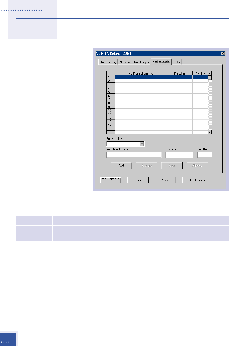
Address table
The address table is
available only when
the gatekeeper is
NOT in use.
Outgoing
destinations using
the VoIP line are set
in this table. The
settings in this table
is used to originate
calls to the outgoing
destinations.
Item Description Default
Address Sets VoIP telephone numbers, IP addresses and up to 100 None
table port numbers*.
36
Sorting the list using each row as a key (Sort with key)
The address table can be sorted by using a VoIP telephone number, IP
address or port number as the key for sorting.
Address table display editing
Use the following methods to edit the contents of the address table. The
changes are saved in the VoIP-TA by clicking on the OK or Save button.
Setup
Page 45

Add: Click on this button to add a VoIP telephone number, IP address or
port number in the address table.
Change: Click on this button to change the contents of the address table.
Click on the line where a change in the VoIP telephone number, IP
address, or port number is to be made, then make the changes in the
selected line.
Clear: Select the line to be cleared, and then click on this button to clear
the entire selected line.
All Clear: Click on this button to clear all information in the address
table.
The VoIP-TA port number is 1720.
*
When specifying another gateway, enter a port number specified for the
call (usually 1720).
Setup
37
Page 46

Details
It is usually not necessary to make any changes in the detailed settings
(Detail). These default settings are changed when the VoIP-TA is not
working properly, which may be due to the particular environment
wherein the unit is being used.
Item Description
Voice setting Used to change the detailed settings related to voice communication. To
display the detailed setup window, click on this button (see example below).
FAX setting Used to change the detailed settings related to facsimile communication. To
display the detailed setup window, click on this button (see pages 41 – 42).
SLIC setting Used to change the detailed settings related to telephone and facsimile units
connected to the VoIP-TA. To display the detailed setup window, click on this
button (see pages 42 –43).
Setup
38
Page 47

Voice settings
Item Description Default
Voice codec Used to specify the packet capability of each voice codec. G.729A 80ms
When Not used is checked off, the VoIP-TA operates G.723.1 60 ms
without using that particular voice codec. The priority G.711 5 ms
sequence of the voice codec used for calls is G.729A,
G.723.1 and G.711 (µ-law/A-law).
Receiving Used to specify the receiving volume, selectable in five Second level
volume level levels. (–16dB, –12dB, –8dB, –4dB, 0dB) from the left.
(–12 dB)
Buffer size Specifies the size of the receive-buffer for voice Second level
for receiving communication (please note that as the receive-buffer from the left.
packet size increases, the voice interruption decreases, but at
the same time, the voice delay increases. Increase the
buffer size if the voice interruption occurs due to
network fluctuations).
RTCP SDES Specifies the send-interval time of RTCP SDES. 5 sec.
send-interval
RTP/RTCP Specifies the time-out value of receiving RTP/RTCP. 30 sec.
receive waiting
Echo Used to turn the echo cancellation ON or OFF, by ON
cancellation activating or deactivating a check mark.
Silent Used to turn the silent suppression ON or OFF, by OFF
suppression activating or deactivating a check mark.
Setup
39
Page 48

Voice codec setting and bandwidth used
G.729A
G.723.1
G.711
Voice codec Data size Voice packet size Usable one-call
setting [ms] [Byte] including header [Byte] bandwidth [kbps]
10 10 50 40.00
20 20 60 24.00
30 30 70 18.67
40 40 80 16.00
50 50 90 14.40
60 60 100 13.33
70 70 110 12.57
80 80 120 12.00
90 90 130 11.56
100 100 140 11.20
110 110 150 10.91
120 120 160 10.67
Voice codec Data size Voice packet size Usable one-call
setting [ms] [Byte] including header [Byte] bandwidth [kbps]
30 24 64 17.07
60 48 88 11.73
90 72 112 9.96
120 96 136 9.07
Voice codec Data size Voice packet size Usable one-call
setting [ms] [Byte] including header [Byte] bandwidth [kbps]
5 40 80 128.00
10 80 120 96.00
20 160 200 80.00
30 240 280 74.67
40 320 360 72.00
50 400 440 70.40
60 480 520 69.33
70 560 600 68.57
80 640 680 68.00
90 720 760 67.56
100 800 840 67.20
110 880 920 66.91
120 960 1000 66.67
40
Default values, set at the time of product shipping, are displayed when
the Restore default button is clicked.
Setup
Page 49

FAX setting
Detailed settings related to facsimile communications via the VoIP line
can be made (it is not necessary to change these settings for facsimile
communications via the PSTN line).
Item Description Default
Control data Specifies the data packet size of facsimile control data. 200 ms
packet size
Image data To specify the image data packet size (for ECM mode, data 100 ms
packet size are divided into packets for each frame, regardless of this setting).
Receive Specifies the receive-buffer for facsimile communications 110 ms
buffer time (please note that as the receive-buffer size becomes larger the
network jitter becomes larger, while the voice delay increases).
TCP/UDP/ To select the protocol used for the facsimile communications TCP
Auto through the IP network.
PAD out Specifies the level of facsimile signal output. -7 dB
Cable length To set the send-equalizer suitable for the length of the cable
for equalizer connected to the facsimile. None
The default values, set at the time of product shipping, are displayed
when the Restore default button is clicked.
Setup
41
Page 50

SLIC setting
Detailed settings can be made for telephone and facsimile units
connected to the VoIP-TA unit.
Item Description Default
Inter digit To set the time-out value of the telephone number entries. 4 sec.
time-out If time-out occurs the system determines that all numbers
have been entered and commences to generate the call.
Ringer frequency Specifies the ringer frequency. 20 Hz
Howler tone Specifies the time for sending the howler tone. 30 sec.
send time
Ringing time Specifies the ringer sounding time intervals for incoming ON1=1000 ms
calls from the VoIP line and PSTN line respectively. OFF1=2000 ms
See the figure below for a graphic explanation. ON2=1000 ms
OFF2=2000 ms
Hookflash To set the minimum and maximum time interval for the Min.=96 ms
detection time Hookflash detection. When an on-hook state exists in the Max.=768 ms
time interval between the specified minimum (
and maximum (Max.), a hooking condition is determined.
Min.)
42
The default values, set at the time of product shipping, are displayed
when the Restore default button is clicked.
Setup
Page 51

V
V
Maintenance
The VoIP-TA is maintained by using the Maintenance Console Software.
The Maintenance Console Software is installed in a PC to communicate
with the VoIP-TA in remote mode via a LAN interface or in local mode via
the RS232C interface. When connecting to the VoIP-TA in remote mode
via a LAN, network settings such as the assignment of IP addresses, must
be already completed first (see Chapter IV, pages 17 – 24, for details on
the Maintenance Console Software).
Functions of the Maintenance Console Software
Item Descriptions Default
Version To display the software version.
Status To display the VoIP-TA operation status.
Update To update unit programs for the VoIP-TA, etc. Available only in
installation mode.
Password To change the password for the connection of the Available only in
change VoIP-TA with the Maintenance Console Software the setup mode.
on a PC in the remote mode, connected via a LAN.
Verifying the Software Version Information
The version of a unit program or the Maintenance Console Software can
be verified.
• Start the Maintenance Console Software and connect the software to
the VoIP-TA (see Chapter IV, page 18, for details on connections).
Maintenance
43
Page 52

• Click the
Help (H) in the menu bar of the main window and select
About VoIP-TA Console Software from the pull-down menu.
• The version
information window
will be displayed
(when the VoIP-TA is
not connected to the
Maintenance Console
Software, only the
Maintenance Console
Software Version is
displayed).
• Click the OK button.
Checking the Operation Status of the VoIP-TA
• Start the Maintenance
Console Software and
establish connection to
the VoIP-TA via the
software (see Chapter IV,
page 18, for details on
connections).
44
• Click on the Status
display button in the
Main window.
• The status of the VoIPTA will be displayed.
Maintenance
Page 53

Explanation of the displayed information
Display Displayed
item
Mode Operation mode Operation mode
Setup mode Setup mode
Installation mode Installation mode
VoIP line Line locked The VoIP line is unusable.
Idle The VoIP line is ready. No communication.
Outgoing Originating via the VoIP line.
Incoming Terminating from the VoIP line.
Telephone call in progress. A call via the VoIP line in progress.
PSTN line Line power is not detected. The PSTN line cannot be detected.
Idle The PSTN line is ready. No communication.
Outgoing Originating via the PSTN line.
Incoming Terminating from the PSTN line.
Telephone call in progress. A call via the PSTN line in progress.
Holding A call via the PSTN line is currently on hold.
LAN Usable The LAN is available.
Unusable The LAN is not available.
VoIP VoIP telephone number Current telephone number of the VoIP-TA.
telephone When a VoIP telephone number is obtained
number from a gatekeeper, the number is displayed on
Call VoIP telephone number VoIP telephone number of the transfer
forwarding destination specified by absent service.
No setting No transfer destination for absent service is set.
contents
Description
the screen. See gatekeeper settings page 34.
Click the Close button.
Maintenance
45
Page 54

Updating Unit Programs
The following unit programs can be updated.
Item Notes
Program 1 (Operation)
Program 2 (G.723.1) DSP program
Program 3 (G.729A) DSP program
Hold tone data µ-law, 8k, 8bit, mono wav file only.
• Start the Maintenance Console Software and connect the VoIP-TA via
the software (
• Switch to the software to the installation mode (see Chapter IV, page
21, for details on the mode change).
• When the VoIP-TA is
switched to the installation
mode, the Update button on
the Main window becomes
active. Click on the
Update button.
• The Update window is
displayed. Select the
program or data type that
needs to be updated.
see Chapter IV, page 18, for details on the connection).
46
If the updated file name and data
*
type are incorrect, the system
cannot perform normal operations.
• Enter the file name of the
data to be updated or click
on the Reference button to
select a file to be installed.
Click on the Update button.
The installation process
will begin.
Maintenance
Page 55

Do not turn off the power of the VoIP-TA during an update process, as it will
*
result in a fault.
If an error occurs in the PC or the power of the VoIP-TA is turned off during an
*
update process, the VoIP-TA cannot perform normal operations. When such
interruptions occur, be sure to update the file again.
• When the update has been completed, click
the OK button.
• Switch the VoIP-TA to the Operation mode
(see Chapter IV, page 21, for details on
mode changes).
Changing the password
The password, used to connect the VoIP-TA to the Maintenance Console
Software, can be changed (be sure to record the new password for later
reference).
Switch the VoIP-TA to the Setup
mode (see Chapter IV, page 21,
for details on mode changes).
• Click on Mode (M) in the
menu bar of the Main window
and select Password change.
• The Password change window
is displayed. Enter the
current password, then the
new password and again the
new password for
confirmation. Click the
OK button.
• Switch the VoIP-TA to the
Operation mode.
The new password will become valid after the VoIP-TA mode change. See
Chapter IV, page 21, for details on mode changes.
Maintenance
47
Page 56

VI
VI
Troubleshooting
If you encounter irregularities with the VoIP-TA, please check the
following list before contacting authorized sales agents or service offices.
Symptom Items to check
Unit does not • Is the power turned on? Check to see if the POWER lamp is lit.
operate. • Is the power plug inserted into the port correctly?
• Is the AC power adapter connected to the power outlet correctly?
ALARM lamp • Is the LAN port link established?
The
continues to blink. • Has gatekeeper started up normally (when in use).
Not operating. • Is the VoIP-TA in Operation mode?
No calls can be • Is the POWER lamp ON and the ALARM lamp OFF?
made. • Is the software set up correctly?
• Is the unit properly connected to the corresponding port?
• Is the LAN port link established? Check to see if the LAN lamp is lit.
• Is the destination telephone number registered correctly?
• Has gatekeeper started up (when in use)?
• Is the information registered in gatekeeper (when in use)?
• Is the setting of the address table correct if gatekeeper is not in use?
• Is the dial signal of the telephone set correctly? (TEL port: DTMF
signal. Telephone lines vary depending upon the contract with the
regional telephone company.)
No calls are • Is the
received. • Is the software set up correctly?
FAX communication • Is the
is not available. • Is the facsimile mode a G3?
The unit cannot be • Is the setting (remote or local) correct?
connected to a PC
for maintenance • Is the VoIP-TA connected to the LAN network?
console. • Is the IP address of the VoIP-TA to be connected correct?
POWER lamp ON and the ALARM lamp OFF?
• Is the unit properly connected to the corresponding port?
• Is the LAN port link established? Check to see if the LAN lamp is lit.
• Is the ringer of the telephone in the ON position?
• Has gatekeeper started up (when in use)?
• Is the information registered in gatekeeper (when in use)?
POWER lamp ON and the ALARM lamp OFF?
In remote mode
• Is the setting of the PC (e.g. network setting) correct?
• Is the PC for the Maintenance Console Software connected to the
PC port of the VoIP-TA?
In local mode
• Is the RS232C cable straight?
• Is the COM port setting of the Maintenance Console Software
correct?
48
Troubleshooting
Page 57

VII
VII
Specifications
Dimensions Approx. 47 (W) x 185 (D) x 155 (H) [mm]
Weight Approx. 0.42 [kg]
Power dissipation 9 [W] or less
Temperature range 0° C to 40° C
TEL port Interface Conventional analogue telephone line
Selection signal DTMF signal
FAX transmission speed 14,400 bps 12,000 bps 9,600 bps
Number of connectable ports One only
LAN port Interface 10BASE-T/100BASE-TX
PC port Interface 10BASE-T/100BASE-TX
LINE port Interface Conventional analogue PSTN
Selection signal DTMF signal
CONSOLE port Interface RS232C (19,200 bps)
Call control Protocol TCP/IP
system Procedure ITU-T recommended H.323 Version 2
Voice real-time Protocol UDP/IP
transfer system Real-time procedure RTP/RTCP
Voice control Voice codec protocol G.711 (µ-law, A-law), G.729A and G.723.1
FAX Protocol TCP/IP, UDP/IP
Real-time procedure T.38
Data setting Interface Local: RS232C Remote: LAN
Number of
Tel. No. digits
Max. 32
7,200 bps 4,800 bps 2,400 bps
Protocol and service port number used with the VoIP-TA.
Note
Usage Protocol TCP/UDP Port number
Voice packet (H.225.0) RTP UDP UDT port No. +6 or +8
Voice packet (H.225.0) RTCP UDP UDT port No. +7 or +9
FAX communication T.38 UDP UDP UDT port No. +31 or +32
Gatekeeper RAS UDP UDP port No. +1
communication (H.225.0)
Gatekeeper detect RAS UDP UDP port No.
Call control (receiving) Q.931 TCP TCP port No. for receiving
Call control (sending) Q.931/H.245/T.38 TCP TCP TCP port No. –TCP port No. +24
FAX communication
Maintenance Oki proprietary TCP 20300
Specifications
49
Page 58

Important Equipment Information
The following information relates to the VoIP-TA compliance with radio
interference requirements of various countries in which this equipment
is sold.
EU Model
VoIP-TA conforms to the following directives:
• Low Voltage Directive: 73/23/EEC
• EMC Directive: 89/336/EEC
• R&TTE Directive: 1999/5/EC (Annex II)
Compliance with these directives implies conformity to the following
European norms:
Safety: EN60950: 1992+A1+A2+A3+A4+A11
EMC: EN55024: 1998
R&TTE: TBR21: 1998
Important Equipment Information
50
EN55022: 1998
EN 61000-3-2: 1995+A1+A2
EN 61000-3-3: 1995
ETSI EG 201 121: v1.1.2
Page 59

Warranty and Service
Our authorized sales agents or service office will respond to your
inquiries and services in a prompt and courteous manner.
Warranty Period
In the event of a problem occurring during the warranty period, all
necessary repairs and replacements will be done free of charge except in
the following circumstances:
• Failure or damage that occurred because the equipment was dropped
or handled roughly.
• Failure or damage due to fire, earthquake, storm or flood, lightning or
other extraordinary natural event.
• Damage due to moisture or salt intrusion, environmental pollution, or
the application of abnormal voltage.
• Failure or damage due to improper operation of the equipment,
maintenance, repair, or modification by unauthorized service staff or
agents.
Following the warranty period
The cost of replacement parts will be charged after expiry of the
warranty period.
Please contact the authorized sales agents or service office for inquiries
regarding service.
Warranty and Service
51
Page 60

Oki Service Offices
Your Local Dealer
Oki Electric Industry Co., Ltd.
Head Office
10-3 Shibaura 4-chome,
Minato-ku, Tokyo 108-8551
JAPAN
Tel: +81-3-5445-6346/6353
Fax: +81-3-5445-6363/6364
URL: http://www.oki.co.jp
London Office
Central House, Balfour Road
Hounslow, Middlesex TW3 1HY
U.K.
Tel: +44-208-219-2110
Fax: +44-208-219-2205
Oki Service Offices
52
Sydney Office
63-85 Victoria Street
Alexandria NSW 2015,
Australia
Tel: +61-2-9310-5711
Fax: +61-2-9310-4611
URL: http://www.oki.com.au
Oki Network Technologies
1101 Cadillac Court
Milpitas, CA 95035
U.S.A.
Tel: +1-408-935-3331
Fax: +1-408-935-3337
URL: http://www.okint.com
 Loading...