

Page 1

Oki Voice Over IP Telephony Adapter
User’s Guide
Version 1.2
Oki Electric Industry Co., Ltd.
Page 2

Page 3

Safety Warning!
This document contains information regarding the safe use of the Oki
VoIP-TA unit. Carefully observe and comply with all safety precautions.
Page 4

© 1999-2000, Oki Electric Industry Co., Ltd. All rights reserved.
The VoIP-TA Internet Telephony Adapter and the Maintenance Console
Software are products of Oki Electric Industry Co. Ltd.
The right to reproduce this manual and/or the Maintenance Console Software is
restricted by the Copyright Act.
No part of this document may be copied, reproduced, stored on a retrieval
system, or transmitted in any form or by any means, electronic, mechanical,
photocopying, recording, or otherwise, in whole or in part, without the written
permission of Oki Electric Industry Co. Ltd.
Information in this document is subject to change without notice.
The contents of this document and the Maintenance Console Software have
been prepared with the utmost care. However, if you notice an irregularity,
please contact an authorized sales agent.
Oki Electric Industry Co. Ltd., assumes no responsibility with regard to
consequences resulting from the use of the Maintenance Console Software and/or
the contents and interpretation of the information contained in this manual.
Ethernet is a registered trademark of Xerox Corporation.
MS-DOS and Windows are registered trademarks of Microsoft Corporation.
Other companies and product names mentioned in this manual my be the
trademarks or the registered trademarks of their respective companies. Oki
Electric Industry Co. Ltd., neither endorses or recommends third-party
products mentioned herein nor assumes responsibility with regard to the use
or performance of these products.
ii
Page 5

Contents
Important Safety Instructions iv
Introduction vi
I Outline 1
The VoIP-TA 1
Features 1
Front panel 2
LEDs 2
Back panel 3
Connectors 3
II Installation 5
Connections 5
Cautions 7
III Placing Calls 8
Via an IP network 8
General operation 8
Services 9
Third party incoming call during another call 9
End-to-end service using DTMF signaling 10
Call transfer during a telephone Call 10
Absent service 12
Details of services 13
Using both a PSTN line and the IP network 13
Using the IP network only 16
IV Troubleshooting 17
V Specifications 18
Important Equipment Information 19
Warranty and Service 20
Contents
iii
Page 6

Important Safety Instructions
When handling or using the VoIP-TA unit, the following safety precautions should
be observed to prevent injury and/or damage to the unit. Use of this equipment in
a manner other than that specified in this and other VoIP-TA documents will void
the product warranty and may result in damage, serious injury or death.
WARNING Incorrect use by neglecting the following instructions
may cause fire, electric shock, unit failure, resulting in
damage, serious injury or death.
• Do not connect a commercial power supply circuit, analogue, digital
(ISDN) or PBX digital telephone line to the LAN or PC port.
• Do not use with power supply voltages other than those specified.
• Do not insert or drop metal objects into any of the openings.
• Do not disassemble or modify this product in any way.
• Do not place any vases, cups, cosmetics, chemicals, pots or any other
containers containing liquids or small metal objects, near the product.
Spillages into the product may cause fire, electric shock or unit failure.
• Do not try to connect or disconnect the power plug with wet hands.
• Insert the power plug fully and securely into the power outlet. To avoid
electric shock, do not use a plug that exposes the terminals when
inserted.
• Avoid star connections as fire or overheating may result.
• Do not put heavy objects on the AC adapter cord or expose it to
excessive heat.
• Do not pull the cord or allow it to overheat as it may be damaged and
could cause fire or electric shock.
• If lightning strikes a neighboring area, stop operating the product by
disconnecting the AC plug (by grasping the power plug, not the cord)
from the power supply outlet.
• Always ground the product properly.
Important Safety Instructions
iv
Page 7

• Do not use AC adapters other than those specified or supplied.
• If liquid enters the unit, immediately disconnect the power plug (by
grasping the power plug, not the cord) from the power outlet and
contact an authorized sales agent or service provider. Continued use
may result in fire or electric shock.
• If smoke or fumes are emitted from the unit, immediately disconnect
the AC plug (by grasping the power plug, not the cord). When smoke
emissions cease, contact a sales agent or service office for repair.
Continued use may cause fire, electric shock or unit failure.
• Use only authorized sales agents or service offices for internal
inspection or repair.
CAUTION Incorrect use by neglecting the following instructions
may cause fire, electric shock, unit failure resulting in
injury or damage.
• Avoid oily, humid or dusty locations, such as on a kitchen table or near
a humidifier.
• Do not place the unit on unstable or inclined surfaces as the unit may fall.
• Avoid locations exposed to direct sunlight or moisture as internal
overheating may occur causing fire or unit failure.
• Wipe away with a dry cloth any water droplets that may be on the
surface of the unit. Water intrusion may cause fire or unit failure.
• Do not cover up the vent holes of the VoIP-TA. If covered, internal
overheating may result causing fire or unit failure.
• Do not unplug the AC power plug by pulling on the cord. Always grasp
the plug portion when disconnecting the AC power plug.
• Disconnect the AC power cord and other connectors when moving the
VoIP-TA.
• For safety, disconnect the AC plug from the power supply outlet (by
grasping the power plug, not the cord) before starting maintenance.
Important Safety Instructions
v
Page 8

Introduction
Welcome to the world of Oki Internet telephony…
The Oki voice over IP (Internet Protocol) telephony adapter, VoIP-TA, is a
self-contained H.323 version 2 compliant communications device that
allows organizations to route both voice and facsimile communications
over any TCP/IP network.
The VoIP-TA is designed to provide a service that is virtually
indistinguishable from that of conventional telephone and facsimile
services.
Use this guide to familiarize yourself with the VoIP-TA. Should you need
to handle the equipment, pay special attention to the procedures and
safety precautions contained in this guide.
vi
Introduction
Page 9

I
I
Outline
The VoIP-TA
The VoIP-TA is a one-channel Internet telephony adapter that provides
Internet telephony services conforming to industry standard H.323
version 2 specifications. It can be connected to a conventional analogue
telephone or G3 facsimile machine.
Once installed, VoIP-TA units use the Internet Protocol (IP) network to
bridge the distance between units at a fraction of the cost associated with
conventional telephony methods.
* Gatekeeper is necessary when more than 100 IP addresses are to
Features
• Compact size and one-channel Internet telephony adapter.
• Automatic telephone routing by specified telephone numbers.
• Smooth and natural telephone calls by optimizing the voice buffer.
• Supports Dynamic Host Configuration Protocol (DHCP manual
• Conforms to the ITU-T recommended H.323 version 2 specifications.
• Supplies real-time Internet facsimile communication.
• Uses high quality voice compression technology.
The Public Switched Telephone Network (PSTN) is supported by VoIP-TA version
Note
1.2 and later. The version number is clearly marked on the bottom of the unit. Please
contact your network manager or authorized sales agent or service office if in doubt,
to avoid incorrect use.
be used.
allocation) for local IP addresses.
Outline
1
Page 10
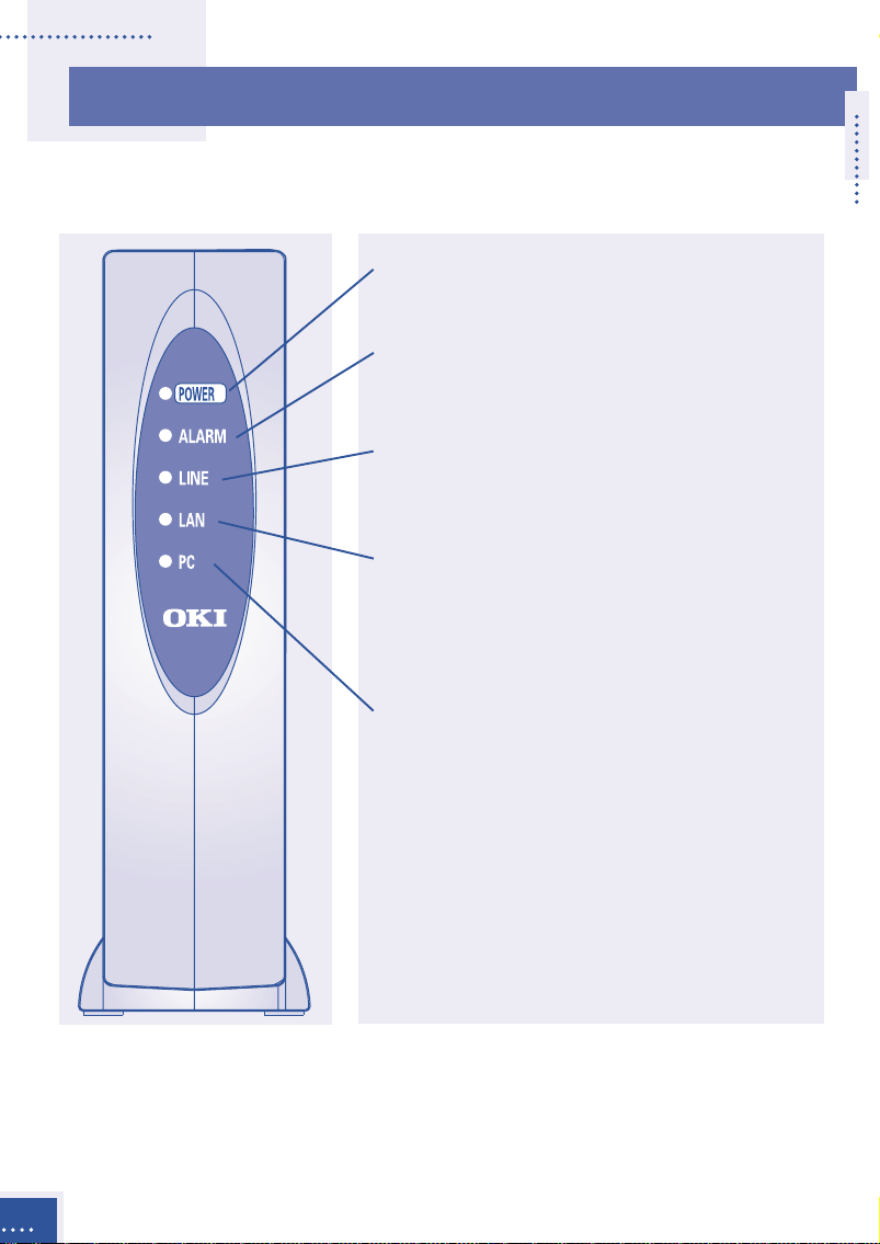
Front panel
LEDs
POWER Indicates power ON when lit.
Green lamp.
ALARM Indicates alarmed condition
detected in unit when lit.
Red lamp. (see table 1 p. 4)
LINE Indicates PSTN line is used
during operation when lit.
Green lamp.
LAN Indicates LAN link is
established and operating
normally when lit . When
blinking, data is being sent.
Green lamp.
PC Indicates link is established
and operating normally when
lit. When blinking, data is
being received.
Green lamp.
Outline
2
Page 11

Back panel
Connectors
TEL Connects a conventional
analogue telephone or G3
facsimile machine. Dial signal:
DTMF signaling only.
LINE Connects to an analogue
public telephone line.
PC* Connects to a PC via a straight
cable (category 3 or higher).
Not for Maintenance Console
Software. Use category 5 for
100BASE-TX.
LAN* Connects to LAN via a cross
cable (category 3 or higher).
Use a straight cable for HUB
connection. Use category 5 for
100BASE-TX.
CONSOLE Connects to a PC (serial port)
for data setup. Use an RS232C
connector cable (straight).
FG Terminal strip for frame
ground.
DC IN 12V Connects an AC adapter.
The communication performances of the LAN and PC ports are always the same and
*
VoIP-TA conforms to the lower of the two. When either the PC or LAN port is 10
BASE-T, both ports are set to 10 BASE-T communication. If a PC is connected to the
PC port during a call, the call may be interrupted for approximately one second.
Please avoid such usage.
Outline
3
Page 12

Table 1
Mode ALARM-LED LINE-LED Status
Initialization Blinks OFF With Gatekeeper:
(1 sec. The system will wait for
intervals) LAN link to be established
while Gatekeeper registers
the VoIP-TA.
Without Gatekeeper:
The system will wait for a
LAN link to be established.
Operation OFF OFF Standby
OFF ON The telephone line is busy.
OFF Blinks When using both IP and
(1 sec. PSTN:
intervals) The PSTN is on hold during
VoIP calls.
When using IP network only:
The absent service is
setting up.
Blinks The handset is off the hook
(0.5 sec. OFF and the howler tone has
intervals) already stopped.
Setup Blinks Blinks Normal operation is not
(0.2 sec. (0.2 sec. available in the Setup
intervals) intervals) mode.
Installation Blinks Blinks Normal operation is not
(0.2 sec. (1 sec. available in the Install
intervals) intervals) mode. The LED lamp may
blink irregularly during the
program installation.
Outline
4
Page 13
II
II
II
II
Connections
Installation
Place the main unit in a vertical position as placing it horizontally could
shorten the life of the unit.
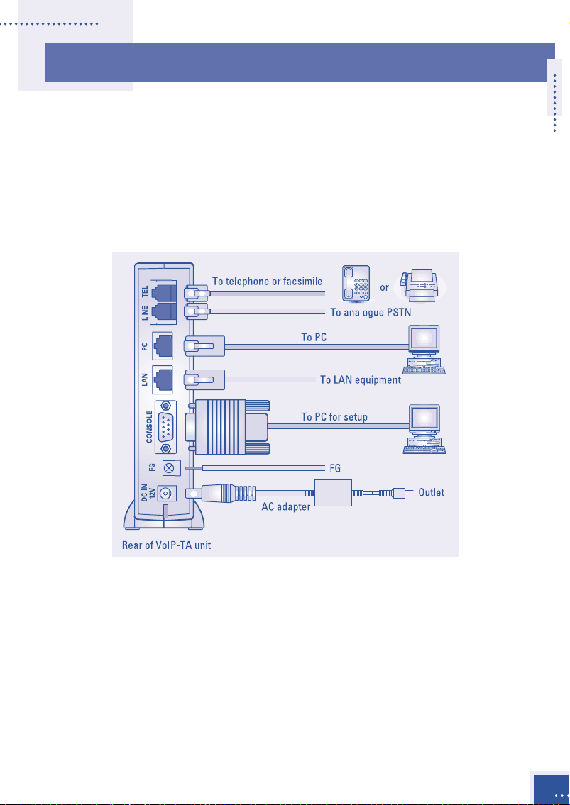
The following illustration shows where equipment should be connected
to the ports at the rear of the VoIP-TA unit.
Analogue telephone or G3 facsimile equipment
Connect an analogue telephone or G3 facsimile machine to the TEL
connector of the VoIP-TA unit via a telephone cord.
To make facsimile connections, the other end terminal equipment should
be compliant with the ITU-T T.38 standard.
Analogue PSTN
Connect an analogue PSTN line to the LINE port at the rear of the VoIP-TA
unit via a telephone cord.
Installation
5
Page 14

Personal computer (PC)
Connect a PC connector to the PC port at the back of the VoIP-TA unit
using an unshielded twisted pair (UTP) straight cable (categories 3 to 5).
If both a PC and LAN are to use 100BASE-TX communications, use
category 5 [max. 100m].
It is recommended that only one PC is connected to avoid voice deterioration.
Note
LAN
Connect the LAN connector to the LAN port at the back of the
VoIP-TA unit via a cross cable (UTP categories 3 to 5). If connecting to a
hub, use a straight cable.
If the LAN is connected by 100BASE-TX and the PC is connected by
100BASE-TX, or if the PC is not connected, use a category 5 cable
[max. 100 m].
CONSOLE (setting up the VoIP-TA with a PC)
Connect the PC for setup on the VoIP-TA by using the serial cable RS232C (9 pin – 9 pin straight) to the CONSOLE port.
FG (grounding)
After connecting the frame ground (FG) cable to the FG port at the back
of the VoIP-TA unit, connect the other end to a ground terminal in the
house or ground it separately.
6
Power source
Connect the supplied AC adapter to the DC IN 12V port at the back of the
VoIP-TA unit. Connect the attached AC adapter to a power outlet.
Installation
Page 15

Cautions
During installation
• All cables used to connect the equipment must be accessories of the
equipment or suitable to fit the equipment.
• Make sure the AC power plug is disconnected from the power outlet
when connecting the FG cable to the unit.
• When an exchange machine, such as PBX or EKTS is connected to the
TEL port of VoIP-TA, the sound quality may deteriorate. Only one
exchange machine should therefore be relayed between the VoIP-TA unit
and telephones.
• Interference noise may occur during telephone calls in areas that receive
strong radio waves, such as near a broadcasting station or CB radio
transmission. If calls are affected in this way, consult your network
manager, an authorized sales agent or service office.
• Do not install the VoIP-TA unit near equipment that generates
magnetism or radio waves such as TV sets, radios, radio machines,
microwave ovens, or inverter-type fluorescent lamps, as this may cause
the unit to malfunction.
During use
• Do not subject the unit to strong impact, such as dropping the unit.
• Do not force cables to connect or disconnect as this may result in faults.
The connector and port should join with reasonable ease.
• When cleaning the exterior of the VoIP-TA, turn it off and disconnect the
unit (by pulling the power plug, not the cord), wipe it with a water damp
cloth and wipe it dry with a soft dry cloth. Do not use volatile thinner,
alcohol or a silicon cleaner under any circumstances as it may result in
damage, discoloration or deformation.
Installation
7
Page 16

III
III
Placing Calls
Via an IP network
Placing and receiving calls with the VoIP-TA unit are usually quite simple
and performed in the same way as conventional telephone networks. In
some cases however, the phone numbers to be used, may differ slightly
from the ones you used previously.
General operation
Outgoing calls
Use a telephone that generates a Dual Tone Multiple Frequency (DTMF)
signal. Pick up the handset and dial a remote party’s telephone number.
Incoming call response
An incoming tone will be emitted from the telephone.
Disconnection
A telephone call can be disconnected by hanging up the handset onto the
telephone receiver.
8
Placing Calls
Page 17

Services
Third party incoming call during another call
You can respond to a third party’s incoming call while you are on
another call.
• A second party
telephone call.
• If a third party calls, a
notification tone is sent
to your telephone.
• You may speak to a
third party by hooking.
* The operation varies
depending on the data
settings. See Details of
Services p. 13
Placing Calls
9
Page 18

End-to-end service using DTMF signaling
DTMF signaling can be used via the IP network for answering machines,
etc. This service is unavailable when the facsimile transmission, via the
VoIP line, is set in the data setup. For details of the data setup, please
contact your network manager.
• Making a telephone call
Call transfer during a telephone call
You can transfer a call during a telephone call. This service is unavailable
when the PSTN is set in the data settings. For details of the data setup,
please contact your network manager.
10
• During a telephone call
Placing Calls
Page 19

• Put the other party on
hold by hooking, and
dial a transfer
destination number.
• You may then speak to
the party at the
transfer destination.
• When you hang up the
handset again the call
will be automatically
transferred to the
destination.
Placing Calls
11
Page 20
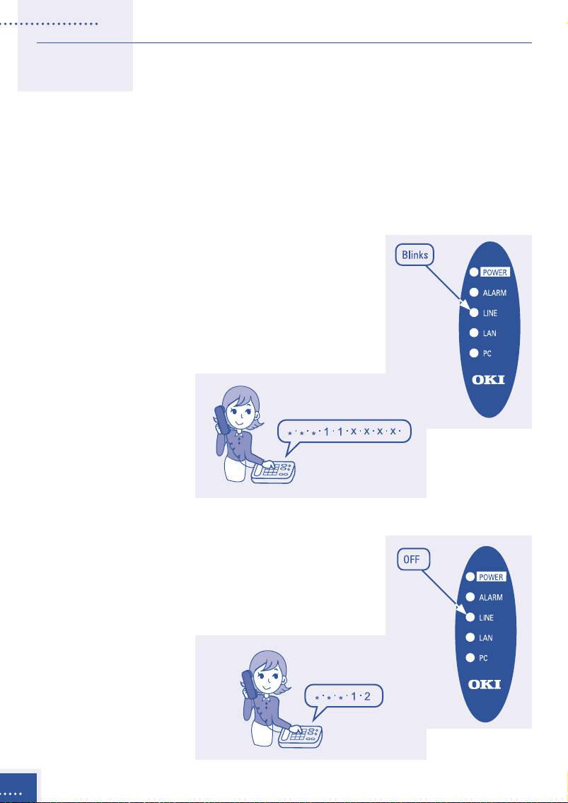
Absent service
If the absent service is registered, an incoming call is transferred to a
registered destination. The transferred call will not be transferred any
further.
This service is inapplicable when a PSTN is set in the data setup. For
details of data setup, please contact your
network manager.
How to register the absent service
Pick up the handset, dial “***11” and the
“destination number to be transferred” and
hang up the handset. When the service is set,
the LINE-LED lamp will blink.
12
How to cancel the absent service
Pick up the handset, dial “***12,” and hang up
the handset. When the service is cancelled, the
LINE-LED lamp will go off.
Placing Calls
Page 21

Details of services
There are two ways to use the VoIP-TA unit; using both a PSTN line and
the IP network or using only the IP network. These services are
determined by the data setup.
Using both a PSTN line and the IP network
Line selection
The selection of a PSTN line or IP network is specified by the first digit of
the phone number set by the Maintenance Console Software. Please follow
the instructions provided by your network manager.
Third party incoming call during another call
For PSTN line receiving services using hookflash (hooking) from
regional telephone service company.
• Response to incoming calls from a PSTN line during a telephone
call using the IP network.
Placing Calls
13
Page 22

• Response to an incoming call from the IP network during a
telephone call using a PSTN line.
• Incoming operation from the IP network during a telephone call
using the IP network.
14
Placing Calls
Page 23

For PSTN line not receiving services using hookflash (hooking).
• Response to an incoming call from a PSTN line during a telephone
call using the IP network.
• Response to an incoming call from the IP network during a
telephone call using a PSTN line.
Placing Calls
15
Page 24

• Incoming operation from the IP network during a telephone call
using the IP network.
Using the IP network only
Incoming call during an existing telephone call.
16
Placing Calls
Page 25

IV
IV
Troubleshooting
If you encounter irregularities with the equipment, please check the
following list before making inquiries to authorized sales agents or
service offices.
Symptom Items to check
Unit does not • Is the power turned on? Check the POWER
operate. lamp to see if it is lit.
• Is the power plug inserted into the port correctly?
• Is the AC power adapter connected to the
power outlet correctly?
The ALARM lamp • Is the LAN port link established?
continues to blink.
The unit does not
operate.
No calls can be • Is the POWER lamp ON and the ALARM lamp
made. OFF?
• Is the unit properly connected to the
corresponding port?
• Is the LAN port link established? Check the LAN
lamp to see if it is lit.
• Is the dial signal of the telephone set correctly?
(TEL port: DTMF signal. Telephone lines vary
depending upon the contract with your regional
telephone company.)
No calls are • Is the POWER lamp ON and the ALARM lamp
received. OFF?
• Are all the connectors properly connected to the
correct ports?
• Is the LAN port link established? Check the LAN
lamp to see if it is lit.
• Is the ringer of the telephone in the ON position?
FAX communication • Is the POWER lamp ON and the ALARM lamp OFF?
is not available. • Is the facsimile mode a G3?
Troubleshooting
17
Page 26

V
V
Specifications
Dimensions Approx. 47 (W) x 185 (D) x 155 (H) [mm]
Weight Approx. 0.42 [kg]
Power dissipation 9 [W] or less
Temperature range 0° C to 40° C
TEL port Interface Conventional analogue telephone line
Selection signal DTMF signal
FAX transmission 14,400 bps 12,000 bps 9,600 bps
speed 7,200 bps 4,800 bps 2,400 bps
Number of Only one
connectable ports
LAN port Interface 10BASE-T/100BASE-TX
PC port Interface 10BASE-T/100BASE-TX
LINE port Interface Conventional analogue PSTN
Selection signal DTMF signal
CONSOLE port Interface RS232C (19,200 bps)
Call control Protocol TCP/IP
system
Voice real-time Protocol UDP/IP
transfer system
Voice control Voice codec protocol G.711 (µ-law, A-law), G.729A and G.723.1
FAX Protocol TCP/IP, UDP/IP
Data setting Interface Local: RS232C Remote: LAN
Number of Max. 32
Tel. No. digits
Specifications
18
Procedure ITU-T recommended H.323 Version 2
Real-time procedure RTP/RTCP
Real-time procedure T.38
Page 27

Important Equipment Information
The following information relates to the VoIP-TA compliance with radio
interference requirements of various countries in which this equipment
is sold.
EU Model
VoIP-TA conforms to the following directives:
• Low Voltage Directive: 73/23/EEC
• EMC Directive: 89/336/EEC
• R&TTE Directive: 1999/5/EC (Annex II)
Compliance with these directives implies conformity to the following
European norms:
Safety: EN60950: 1992+A1+A2+A3+A4+A11
EMC: EN55024: 1998
EN55022: 1998
EN 61000-3-2: 1995+A1+A2
EN 61000-3-3: 1995
R&TTE: TBR21: 1998
ETSI EG 201 121: v1.1.2
Important Equipment Information
19
Page 28

Warranty and Service
Our authorized sales agents or service office will respond to your
inquiries and services in a prompt and courteous manner.
Warranty period
In the event of a problem occurring during the warranty period, all
necessary repairs and replacements will be done free of charge except in
the following circumstances:
• Failure or damage that occurred because the equipment was dropped
or handled roughly.
• Failure or damage due to fire, earthquake, storm or flood, lightning or
other extraordinary natural event.
• Damage due to moisture or salt intrusion, environmental pollution, or
the application of abnormal voltage.
• Failure or damage due to improper operation of the equipment,
maintenance, repair, or modification by unauthorized service staff or
agents.
Following the warranty period
The cost of replacement parts will be charged after expiry of the
warranty period.
Warranty and Service
20
Please contact the authorized sales agents or service offices for inquiries
regarding service.
Page 29

Oki Service Offices
Your Local Dealer
Oki Electric Industry Co., Ltd.
Head Office
10-3 Shibaura 4-chome,
Minato-ku, Tokyo 108-8551
JAPAN
Tel: +81-3-5445-6346/6353
Fax: +81-3-5445-6363/6364
URL: http://www.oki.co.jp
London Office
Central House, Balfour Road
Hounslow, Middlesex TW3 1HY
U.K.
Tel: +44-208-219-2110
Fax: +44-208-219-2205
Sydney Office
63-85 Victoria Street
Alexandria, NSW 2015,
Australia
Tel: +61-2-9310-5711
Fax: +61-2-9310-4611
URL: http://www.oki.com.au
Oki Network Technologies
1101 Cadillac Court
Milpitas, CA 95035
U.S.A.
Tel: +1-408-935-3331
Fax: +1-408-935-3337
URL: http://www.okint.com
Oki Service Offices
21
Page 30

Oki Electric Industry Co., Ltd.
3PP3507-4104P002
 Loading...