

Oki FAX 5650 SERVICE MANUAL
OKIFAX 5650
Facsimile Machine
SERVICE
MANUAL

Table of Contents Page
Service Guide OKIFAX 5650
0 Introduction
Preface 1
1 General Information
1.1 General Performance 2
1.2 General User's Function 3
1.3 General Maintenance Functions 4
1.4 General Appearance 5
1.5 Basic Performance Specifications 6
....Table 1.5.1 (1/8) Basic Performance Specifications 7
....Table 1.5.1 (2/8) Basic Performance Specifications 8
....Table 1.5.1 (3/8) Basic Performance Specifications 9
....Table 1.5.1 (4/8) Basic Performance Specifications 10
....Table 1.5.1 (5/8) Basic Performance Specifications 11
....Table 1.5.1 (6/8) Basic Performance Specifications 12
....Table 1.5.1 (7/8) Basic Performance Specifications 13
....Table 1.5.1 (8/8) Basic Performance Specifications 14
@1.6 Reports and Lists 16
....Call-back Message (Example) 17
....Sender ID Format: (Example) 18
....TSI Printing (Example) 19
....Cancel Report Format: Power Outage Report (Example) 20
....Activity Report (Example) 21
....Message Confirmation Report 22
....Broadcast Entry Report (Example) 23
....Broadcast Confirmation Report (Example) 24
....Confidential Rx Report (Example) 25
....Telephone Directory (Examples 1 through 6) 26
........Telephone Directory P1 26
........Telephone Directory P2 26
........Telephone Directory P3 26
........Telephone Directory P4 26
........Telephone Directory P5 26
........Telephone Directory P6 26
........Telephone Directory P7 26
........Telephone Directory P8 26

Table of Contents Page
1.7 Configuration 27
....Configuration Report P1 27
....Configuration Report P2 27
....Configuration Report P3 27
....Activity Memory Files 27
....Protocol Dump 27
1.8 Self-Diagnosis Report 27
....Transmission (Except Polling TX) 27
....Reception (Except Polling RX) 27
....Polling TX 27
....Polling RX 27
....Function Combinations during Communications 27
....Preparation TX as Dual Access 27
....Use Default Setting (1/2) 27
....Use Default Setting (2/2) 27
....Technical Default Setting (1/2) 27
....Technical Default Setting (2/2) 27
....Default Setting of Dial Parameter 27
....Plug & Play ID 27
....XPARA Bit 27
2 Installation Procedures
2.0 Setup Information 28
....2.1 General 28
....2.1.2 Site Selection 29
....2.1.3 Unpacking 30
....2.1.4 Check of Contents 31
....2.1.5 Installation of Attachments 32
....2.1.6 AC Cord Connection 33
....2.1.7 Telephone and Line Connections 34
....2.1.8 Packing for Shipment 35
2.2 Initial Settings 36
....2.2.1 General Procedure of Key Operation 37
....2.2.2 Technical Functions 38
....2.2.3 Technical Functions Table 39
....2.2.4 (1/2) Technical Default Setting 39
....2.2.5 (2/2) Technical Default Setting 39

Table of Contents Page
....2.2.6 TEL/FAX Automatic Switching 40
....2.2.7 TAD Mode 41
....2.2.8 Technical Functions Example 42
........Technical Functions 01 to 12 43
........Technical Functions 13 to 17 44
........Technical Functions 18 to 23 45
........Technical Functions 24 to 29 46
........Technical Functions 30 to 41 47
........Technical Functions 42 to 43 47
....2.2.9 Table G3 Fallback Object Service Code List 47
....2.2.10 User's Functions 48
........Feature Specifications 49
........Dual Access Combination Table 50
........One-Touch Key Operations 52
........One-Touch Key Program Settings 53
........Function Program 54
........User's Functions Table 56
....2.2.11 User's Functions Example 55
....2.2.12 User's Functions Table 55
........2.2.12.1 Clock Adjustment 57
........2.2.12.2 Dual Access Operation 58
........2.2.12.3 System Data Programming 59
........2.2.12.4 Dial Parameters Settings 60
........2.2.12.5 Dial Parameters Settings Table 61
........2.2.12.6 Off-line Tests 62
........2.2.12.7 On-line Tests 63
2.3 Installation of Optional Units 64
....1. Installation of the Memory Board 65
....2. Installation of CTR (PC interface) board (OF5400 only) 66
....3. Installation of an Optional Telephone Set 67
....4. Second Paper Cassette Unit 68
3 Brief Technical Description
Electric Photographic Process Flow 70
3.1 Fundamentals of the Electro-Photographic Process 69
3.2 Actual Electo-photographic Process 71
3.3 Boards and Units / Block Diagram 72

Table of Contents Page
....Block Diagram 73
3.4 Overall Dimension and Mechanical Structure 74
4 Disassembly
4.1 General 75
....4.1.1 Precautions for Parts Replacement 76
4.2 Tools 77
4.3 How to Disassemble and Reassemble 78
........Disassembly Procedure Flow 4.1 (1of 2) 79
........Disassembly Procedure Flow (Figure 4.1) 2 of 2 80
....4.3.1 LED Print Head 81
....4.3.2 Image Drum, Covers (Rear, NCU, Main) Separation
Plate, Boards (NCU, Modem)
....4.3.3 Control Panel Assembly, Paper Guide (U) Assembly 83
....4.3.4 Sub-roller, ADF Roller Assembly, Pinch Roller, Contact
Image Sensor, Document Detectors (PC1 and PC2)
....4.3.5 Motors (Resist, Drum), Assemblies (Release Guide,
Manual Guide) Stacker Cover, Fusing Unit
....4.3.6 Lower Base, Motor Assembly, Back-up Roller, Transfer
Roller
....4.3.7 Resist Roller, Hopping Roller, Sensor Plates 86
....4.3.8 MCNT Board, Power Supply Unit, Contact Assembly 86
5 Adjustments
5.1 Setting of LED Print Head Drive Time 89
5.2 Confirmation Items 90
5.3 Measurement 91
....Measurement Points on M60 Board 92
6 Cleaning and Maintenance
6.1 Consumables Replacement 93
....Service Technician Replaceable 94
....Replaceable Items Diagram 95
....Others - Reliability 93
6.2 Routine Inspection 97
....Routine Inspection Table 98
....Preventative Maintenance Diagram 99
6.3 Printer Counter Display/Clear (User) 100
6.4 Printer Counter Display/Clear (Service) 101
82
84
85
86

Table of Contents Page
6.5 Self-Diagnosis Test 102
....Self-Diagnosis Report 103
6.6 Sensor Calibration Test 104
6.7 LED Test 105
6.8 Tone Send Test 106
6.9 High-speed Modem Send Test 107
....High-speed Modem Send and Receive Test Diagram 108
6.10 High-speed Modem Receive Test 109
6.11 MF Send Test 110
6.12 Tone (TEL/FAX) 111
6.13 Protocol Data Dump 112
....Protocol Dump 113
....Data Analysis 114
....FCF - Facsimile Control Field Conversion Table 115
6.14 System Reset 116
6.15 Service code 117
....Service Codes Table 118
7 Troubleshooting
7.1 Overview 119
....7.1 Overall Troubleshooting Flow Chart 120
....7.2 No LCD Operation 121
....7.3 Alarm LED On 122
....7.4 Printing Test Failure 123
....7.5 No Local Copy 124
....7.6 Auto Dial Failure 125
....7.7 Transmission Problem 126
....7.8 Auto Reception Failure 127
....7.9 Reception Problem 128
....7.10 Sensor Calibration Test 129
....7.11 LED Test 130
....7.12 Tone Send Test 131
....7.13 High-speed Modem Test 132
....7.14 MF Send Test 133
....7.15 Tone (TEL/FAX) Send Test 134
....7.16 No Acoustic Line Monitor 135
....7.17 Low Power Supply Unit 131

Table of Contents Page
....7.18 High Power Supply Unit 131
....7.19 No Document Feeding 137
....7.20 Multiple Document Feeding 138
....7.21 Document Skew 139
....7.22 Document Jam 140
....7.23 Printer Unit 141
........7.23.1 Precautions 142
........7.23.2 Troubleshooting Flow Charts of Printer Unit 143
............Overall Troubleshooting Flowchart 144
............1: Top Cover is Open 145
............2: Replace Image Drum Message 146
............3: Engine Controller Error 147
............4: Fan Motor Rotation Error 148
............5: Fuser Unit Thermal Error 149
............6: Paper Jams 150
............7: No Paper Tray or No Paper 151
............Action Items (Printer Unit-LCD Message) Table 152
........7.23.3 Image Problems Table 153
............Sample Image Problems 154
............8: Light or Blurred Output 155
............9: Smeared Background on Output 156
............10: Blank Output 157
............11: Vertical Black Stripes on Output 158
............12: Evenly Spaced Marks on Output 159
............13: Missing Print on Output 160
............14: Vertical White Stripes on Output 161
............15: Poor Fusing 162
8 PC Board Description
8.1 Unit Configuration and Block Diagram 164
....Block Diagram 165
....Block Diagram Abbreviations 166
8.2 Function of Each Unit 167
8.3 Signal Flow Explanation 168
....(1) Copy Mode 169
....Copy Picture Signal 170
....(2) G3 Send Mode 171

Table of Contents Page
....G3 Send Pciture Signal 172
....(3) G3 Receive Mode 173
....G3 Receive Picture Signal 174
....(4) PC Print 175
....PC Print Picture Signal 176
....(5) PC Scanner 177
....PC Scanner mode 178
....(6) PC-FAX G3 TX 179
....PC-FAX G3 RX 180
....(7) PC-FAX G3 RX 181
8.4 Main Control Board (M60) Circuit Diagrams 183
....8.4.1 M-60 - Related Signals of CPU 184
....8.4.2 M60 - FLS, MASK and Real Time Clock Circuit
186
Diagram
....8.4.3 CIS - Contact Image Sensor 186
....8.4.4 IEXSEED300 Diagram 192
....8.4.5 M60 - Related Signals of Send Motor 188
....8.4.6 M60 - Related Signals of Drum / Resist Motor 194
....8.4.7 M60 - Related Signals of LED Head & Fan Motor & 2nd
196
Tray
....8.4.8 M60 - Audio Monitor Circuit 200
....8.4.9 M60 - Related Signals of Modem 202
....8.4.10 M60 - Related Signals of PLD 204
....8.4.11 M60 - NCU - P60 Boards 206
....8.4.12 M60 - MEM - CTR (PC Interface) 209
....8.4.13 M60 - Sensors & Switch / Fuser Unit Temp / Voltage
214
Controls
8.5 OPE (P60) Circuit Diagram 219
....Block Diagram of OPE (operation unit) Diagram 220
8.6 EN9 and INU Circuit Diagram 220
....Block Diagram of EN9 220
....Block Diagram of INU 220
8.7 Power Supply Board 220
8.8 High-Voltage Power Supply Circuit (H08) 220
8.9 MEMO (memory) Circuit Diagram (option) 220
8.10 TQSB (Second tray) Circuit Diagram: option

Table of Contents Page
8.11 CTT (PC Interface Unit) Circuit Diagram (option)
8.12 TELU, TEL-W2, TEL-W1, TEL-W2D and TEL-W2F Circuit
Diagram (option)
....8.12.1 Explanation of TEL circuit diagram
....8.12.2 TEL-W2 circuit diagram
....8.12.3 TEL-W1 circuit diagram
....8.12.4 TEL-W2D circuit diagram
....8.12.5 TEL-W2F circuit diagram
8.13 NTIF (NCU and TEL interface) Circuit Diagram (option)
8.14 OKIFAX 5650 Facsimile Transceiver
9 Descriptions of Print Operation
Overview 270
B.1 Mechanical Components 271
....1) Image drum cartridge 272
....2) Resist motor 273
....3) Drum motor 274
....4) LED head 275
....5) Fuser 276
....Layout of Print Station Components 277
B.2 Description of Print Operations 278
....B2.1 Process Operations 279
........1) Hopping and feeding 280
........2) Charging 281
........3) Exposure 282
........4) Developing 283
........5) Transfer 284
........6) Fusing 285
........7) Cleaning 286
........8) Cleaning of rollers 287
....B.3 Errors 288
........B.3.1 Errors List 289
........B.3.2 Major Trouble Errors 290
............B.3.2.1 Fuser Error 291
............B.3.2.2 Fan Error 292
............B.3.2.3 Paper Feed Monitoring 293
............B.3.2.4 2'nd Tray Communication Error (Printer Alarm 2) 294

Table of Contents Page
............B.3.2.5 Cover Open 295
........B3.3.3 Recoverable Errors 296
............B3.3.3.1 Toner Low Detection 297
............Composition 298
............Operation 299
............Operation during toner full state 300
............Operation during toner low state 301
............Low Toner Alarm 302
....B.4 Other Special Cases 303
........B.4.1 Manual Paper Feed 304
........B.4.2 Cleaning 305
A Circuit Diagrams & Block Diagrams
C.1 General Information 306
B Parts List
Assembly 307
1: Cabinet Assembly 308
2: Control Panel Assembly 309
3: Printer Assembly 310
4: Base Assembly 312
5: Scan Unit 314
6: Paper Guide U Assembly 315
7: Cables 316
9A: Second Paper Feed (Option) 318
C Second Paper Tray (option)
1. Outline 325
....1.1 Functions 326
....1.2 External View and Component Names 327
2. Mechanism Description 328
....2.1 General Mechanism 329
....2.2 Hopper Mechanism 330
3. Parts Replacement 331
....3.1 Precautions Concerning Parts Replacement 332
....3.2 Parts Layout 333
....3.3 Parts Replacement Methods 334
........3.3.1 Stepping Motor (Hopping) 335
........3.3.2 TQSB2-PCB 336

Table of Contents Page
........3.3.3 Hopping Roller Shaft Assy and One-way Clutch Gear 337
4. Troubleshooting 338
....4.1 Precautions Prior to the Troubleshooting 339
....4.2 Preparations for the Troubleshooting 340
....4.3 Troubleshooting Method 341
5. Connection Diagram 343
....5.1 Interconnection Diagram 344
....5.2 PCB Layout 345
6. Parts List 346
(Not Categorized)
C Second Paper Tray (option)
........4.3.1 LCD Status Message List 342

Page: 1
Service Guide OKIFAX 5650
Chapter 0 Introduction
Preface
This manual is intended to be used for installing and maintaining OKIFAX5650 facsimile unit.
Maintenance of the OKIFAX 5650 is assumed to be conducted at the following levels:
Assembly-level maintenance for mechanical portionsl
Unit-level maintenance for electrical at portionsl
CAUTION: DANGER OF EXPLOSION IF BATTERY IS INCORRECTLY REPLACED. REPLACE ONLY WITH THE SAME OR EQUIVALENT TYPE RECOMMENDED BY
THE MANUFACTURER. DISCARD USED BATTERIES ACCORDING TO THE MANUFACTURER'S INSTRUCTIONS
and
ATTENTION: IL Y A DANGER D'EXPLOSION S'IL Y A REMPLACEMENT INCORRECT DE LA BATTERIE. REMPLACER UNIQUEMENT AVEC UNE BATTERIE DU
MEME TYPE OU D'UNT TYPE RECOMMANDE PAR LE CONSTRUCTEUR. METTRE AU REBUT LES BATTERIES USA GEES CONFORMEMENT AUX
INSTRUCTIONS DU FABRICANT.
Programming procedures of the following user functions are not described in this maintenance manual.
Please refer to user's guide.
One-touch key programmingl
Two-digit auto dial programmingl
Group settingl
Programming mail box passwordl
Memory operationl
© Copyright 2001 Oki Data Corporation
This manual is subject to alteration without prior notification.
Copyright 2000, Oki Data, Division of OKI America, Inc. All rights reserved. See the Oki Data Business Partner Exchange
(BPX) for any updates to this material. (http://bpx.okidata.com)

Service Guide OKIFAX 5650
1.1 General Performance
(01) Type of appearance
Desktop typel
(02) Applicable lines
Public switched telephone network (PSTN)l
Private branch exchange (PBX)l
(03) Compatibility
ITU-T Group 3 facsimile transceiverl
ITU-T Group 4 facsimile transceiverl
(04) Document width
Max. 216 mm (8.5 inches [North American Letter])l
Min. 208 mm (5.83 inches [ISO A5 size])l
(05) Effective reading width
Max. 215 mm (8.46 inches) (North American Letter)l
Max. 208 (ISO A4 size) l
(06) Scanning length
128 mm to 356 mm (5.06 inches to 14 inches)l
(Length setting: Unlimited (1500 mm) is also available.)
(07) Automatic document feeder (ADF)
30 sheets (Letter/A4-size: 20-1b bond. Oki Data recommended paper)l
15 sheets (Letter/A4-size: 13 to 28-1b bondl
(08) Recording paper or sheet
First cassette: l NA Letter/NA Legal/A4-size plain paper cut
Second cassette (Option): l NA Letter/NA Legal/A4-size plain paper cut
Manual loading feeder:l
(Single Sheet Feeder)
* Oki Data recommended paper
N/A = North America
(09) Printable width
North American Letter: l 211.3 mm (8.32 inches) / 203.2 mm (8 inches) for
North American Legal: l 211.3 mm (8.32 inches) / 203.2 mm (8 inches) for
ISO A4:l 206 mm ( 8.11 inches) / 197.3 mm (7.77 inches) for
Chapter 1 General Information
Page: 2
250 sheets capacity (20-1b bond*)
500 sheets capacity (20-1b bond*)
Transparency for overhead projector, applicable.
Sheet size: NA Letter/NA Legal/A4-size
assured
quality
assured quality
assured quality

(10) Printable length
Letter:l
Legal: l
ISO A4: l
(11) Copy stacker
Max. 100 sheets (20-lb bond, Oki Data recommended paper), face down l
stacking
(12) Scanning resolution
a) Horizontal
300 dots/inchl
b) Vertical
Transmission mode: 3.85 line/mm (STD)
COPY mode: 7.7 line/ mm (FINE) or
Note: 300 dpi x 300 x dpi (Transmission is available)
(13) Scanning method
2592 bits contact image sensorl
(14) Recording resolution
a) Horizontal:
300 dots/inch
b) Vertical
Variable: Automatically adjusted to the paper length.
(15) Recording method
211.3 mm (8.32 inches / 2496 bit) or 216.7 mm (8.53 inches / 2560 bit) LED Headl
(16) Minimum scan line time for reception
When receiving from OKIFAX or ECM:l 0 ms
When receiving from non- OKIFAX and non ECM:l 10 ms at 3.85 line/mm
(17) Print speed
Max. 8 sheets per minutel
273.4 mm (10.76 inches) / 266.7 mm (10.49 inches) for
assured quality
349.6 mm (13.76 inches) / 342.9 mm (13.49 inches) for
assured quality
291 mm (11.46 inches) / 284.3 mm (11.19 inches) for
assured quality
7.7 line/mm (FINE)
15.4 line/mm (EX.FINE) or
300 dot/inch (EX.FINE)
300 dot/inch (EX.FINE)
(300 to 395 dot/inch),
STD mode (3.85 to 5.06 line/mm)
FINE mode (7.7 to 10.13 line/mm)
EX-FINE mode (15.4 to 20.24 line/mm)
Fixed: STD mode: 3.85 line/mm
FINE mode: 7.7 line/mm
EX-FINE mode : 15.4 line/mm
PC-Print: 300 dot/inch
5 ms at 7.7 line/mm

(18) Preheating time
Approx. 20 sec. (Standby to Print)l
(19) Coding scheme
Modified Huffman (MH)l
Modified READ (MR)l
Modified Modified READ (MMR)l
(20) Modem
ITU-T Rec. V.29: 9600 bps for use on point-to-point 4-wire leased telephone type circuitl
ITU-T Rec. V.27 ter: 4800 bps modem for use in PSTN (Public Switched Telephone Network)l
ITU-T Rec. V.21 channel 2: 300 bps duplex modem for PS TNl
ITU-T Rec. V.17: 2-wire modem for fax application up to 14.4 kbpsl
ITU-T Rec. V.34: l
Note: A modem operating at data signaling rates of up to 33,600 bits/s for use on the general switched telephone network and on leased
point-to-print 2-wire telephone-type circuits.
(21) Transmission speed
3 sec. per sheet of ITU-T No. 1 sample document l
Note: The speed denotes the time interval corresponding to phase C (message transmission phase) as referred to ITU-T T.30.
(22) Protocol
ITU-T Rec. T.30l
OKI special protocols: High-speed protocoll
(23) Error correction mode (ECM)
(24) Communication mode
Half duplexl
(25) Memory capacity
Basic modell 2.5 byte
Optional memoryl 2.0/5.0 M byte memory board can be added.
(26) Liquid crystal display (LCD)
Two rows of 20 characters for operation guidance, check and various kinds of informationl
(27) Power source
Nominal input voltage 120 VAC for ODA versionl
Nominal input voltage 230 VAC for INT’L versionl
(28) MFP (Multi- Function Peripheral) function (Option)
By installing the optional board (CTR board), the MFP function can be l
realized:
PC Printer Function
PC Scanner Function
PC Fax Modem Function
Location Programming Function
(29)
Fax2Net: Provider type (option)
The following functions are available:
Fax over IP
Fax to E-mail
Virtual E-mail

Broadcast
Web Retrieval
Prepaid and Registration
Note: For details, see "OKIFAX 5650 Product Specification for Fax2Net".
Note: For details, see "Product Specification for MFP".
Copyright 2000, Oki Data, Division of OKI America, Inc. All rights reserved. See the Oki Data Business Partner Exchange
(BPX) for any updates to this material. (http://bpx.okidata.com)

Service Guide OKIFAX 5650
1.2 General User's Function
(01) Transmit mode
Automatic transmit model
Manual transmit model
(02) Receive mode
Automatic receive model
Manual receive model
TEL/FAX automatic switchover model
TAD model
Memory only receive model
Forwarding model
PC receive mode (This function is the standard for Oki Data).l
(03) Dual access
(04) Voice request
(05) Automatic redial
(06) Last number redial (Manual redial)
(07) Local copy including multiple copies
Max. 99 copies of documentl
(08) Sender identification (Sender ID)
(09) Personal identification (Personal ID)
(10) Polling transmission
Feeder polling transmissionl
Memory polling transmissionl
(11) Polling reception
Bulletin Poll transmission (when Box number is opened).
(12) Selective polling
16 boxesl
(13) Acoustic line monitor
5 level selectablel
(14) Telephone handset (option)
(15) Automatic alternate selecting call
(FAX No. + FAX No. can be registered in one-touch keys).
(16) Delayed transmission
Delayed broadcastl
Delayed transmissionl
- 20 specified times
(17) Relay broadcast initiate
Feeder relay broadcast initiatel
Chapter 1 General Information
Page: 3

Memory relay broadcast initiatel
(18) Subaddress transmission
(19) Confidential message transmission (Hopper 1 station)
(20) Confidential message reception
16 mail boxesl
(21) PHOTO mode
64 scale gradations l
(22) G3 sequential broadcast (Memory)
Broadcast model
200 stations at maximuml
Delayed broadcast model
(23) No paper/no toner reception
(24) Memory-only reception
Memory reception even if paper does not run out
(25) Distinguishing Text from picture
(26) Page re-transmission (Only in case of memory TX mode)
(27) Vertical reduction printing (Reduction rate is from 100% to 75%)
Reduction rate is from 100% to 75% (Legal to Letter)
(28) Horizontal reduction (RX, Copy: Reduction rate is from 93% to 98%)
(29) Smoothing printing (In case of 8 dot/mm x 3.85, 7.7 or 15.4 line/mm ---> 300 dot/inch x 784 line/inch)
Turn off in the PC print model
(30) Programmed key operation ("F" key + "OT" key)
(31) Auto dialing
One-touch dialing: 40 locationsl
Two-digit automatic dialing: 150 locationsl
Keypad dialingl
Chain dialingl
Mixed dialingl
Group dialing: 20 dialing groups (190 locations)l
(32) Real-time dialing
(In case of optional handset is installed or Hook key)
(33) Automatic pause signal insertion
(34) Manual feeder local copy
(35) Telephone directory (Alpha search) dialing
(36) TEL/FAX automatic switching
(37) Time and date printing
(38) Closed users group (Direct mail rejection)
(39) Transmission contrast and resolution control
(40) Key touch tone
(41) Printer counter display (For drum, toner, total print)
(42) Total page counter (Scan)
(43) Quick scanning 3 sec. minimum --> A4 size 3.85 / mm
(44) Time and date setting

(45) PC interface (option)
Standardl
(46) Language selection
2 language (LCD and Reports)l
(47) Fax forwarding
(48) 4 digit indication of YEAR
(49) Memory password programming
(50) Fax network programming
(51) Fax2Net service
(52) Restrict ID programming
(53) Reports
Activity reportl
Protocol report (Service man setting)l
Message confirmation report (Single address or multiple addresses)l
Broadcast entry report (Broadcast)l
Transmission error reportl
Confidential reception reportl
Configuration reportl
Telephone directoryl
Power outage reportl
Log reportl
Copyright 2000, Oki Data, Division of OKI America, Inc. All rights reserved. See the Oki Data Business Partner Exchange
(BPX) for any updates to this material. (http://bpx.okidata.com)

Service Guide OKIFAX 5650
1.3 General Maintenance Functions
1) Local tests
(01) Self-diagnosis
CPU ROM/RAM checkl
FLASH (/MASK) memory check (Program, Language, Default)l
Modem versionl
RAM checkl
RAM check (MEMORY board: option)l
PC-IF board (parallel) checkl
Print testl
(02) Sensor calibration (Adjustment of scanning level)
(03) LED test
(04) Tone send test (When NCU board is installed).
(05) Multi-frequency (MF) send test (When NCU board is installed).
(06) High-speed modem send test (When NCU board is installed).
(07) High-speed modem receive test (When NCU board is installed).
(08) Tone (TEL/FAX) test (When NCU board is installed).
2) Technical function
Chapter 1 General Information
Page: 4
3) System reset
All data clearl
Location data clearl
Configuration data clearl
4) Default type set
5) PC loading
Copyright 2000, Oki Data, Division of OKI America, Inc. All rights reserved. See the Oki Data Business Partner Exchange
(BPX) for any updates to this material. (http://bpx.okidata.com)
Service Guide OKIFAX 5650
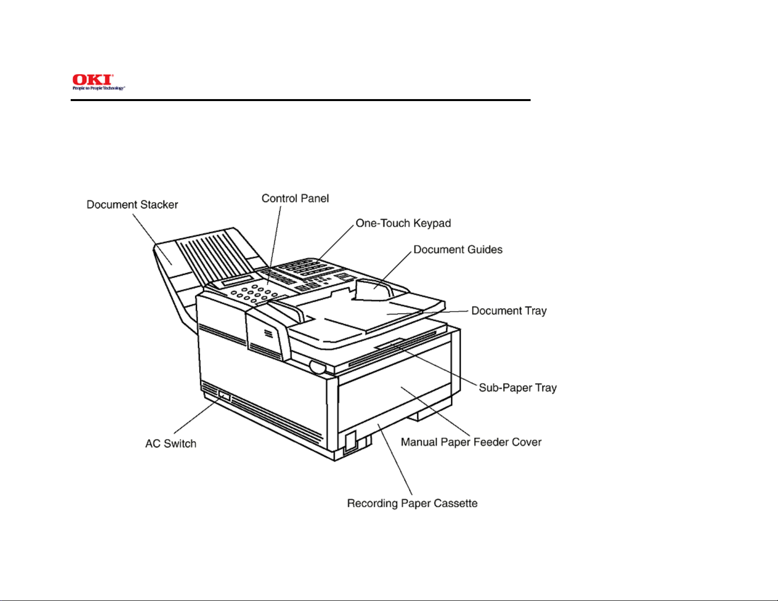
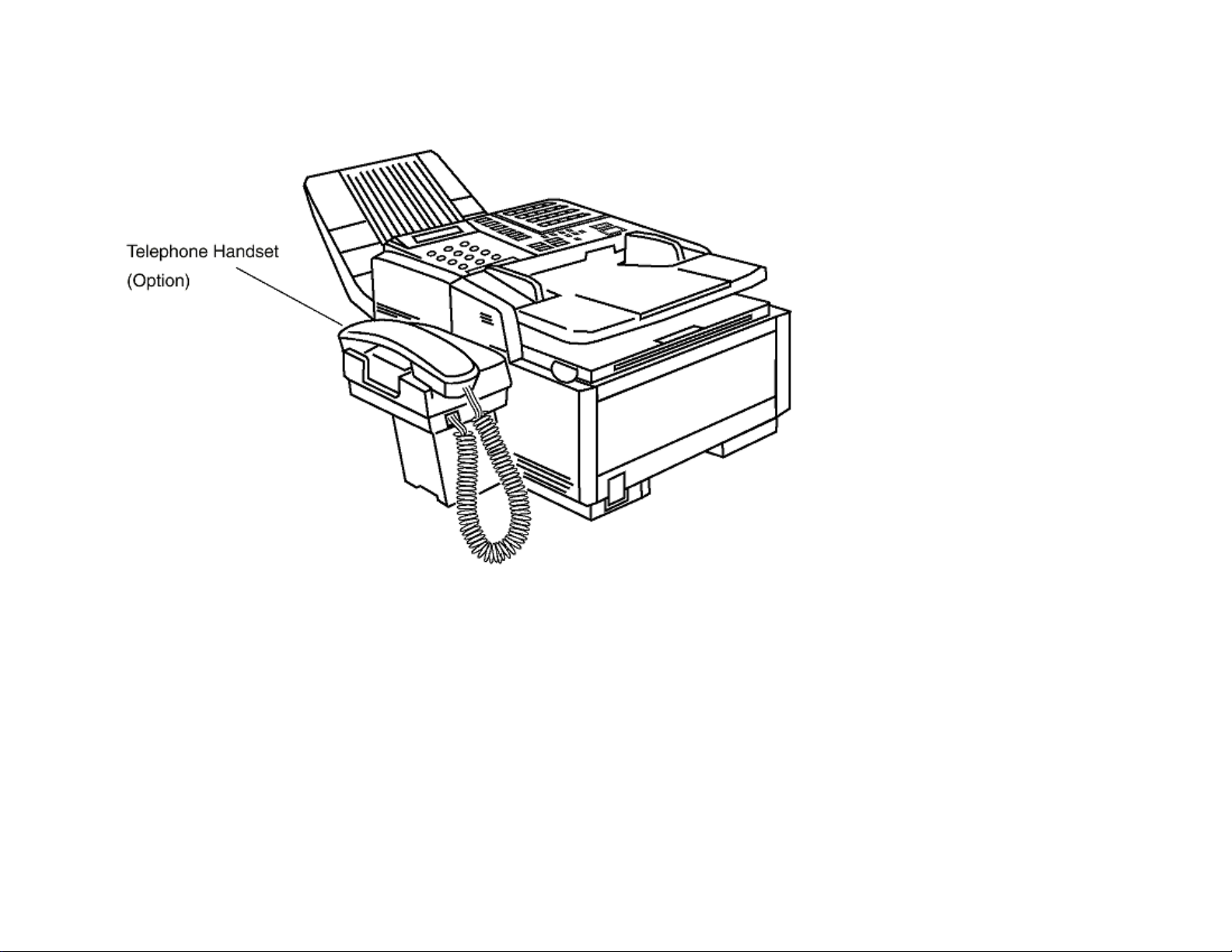
1.4 General Appearance
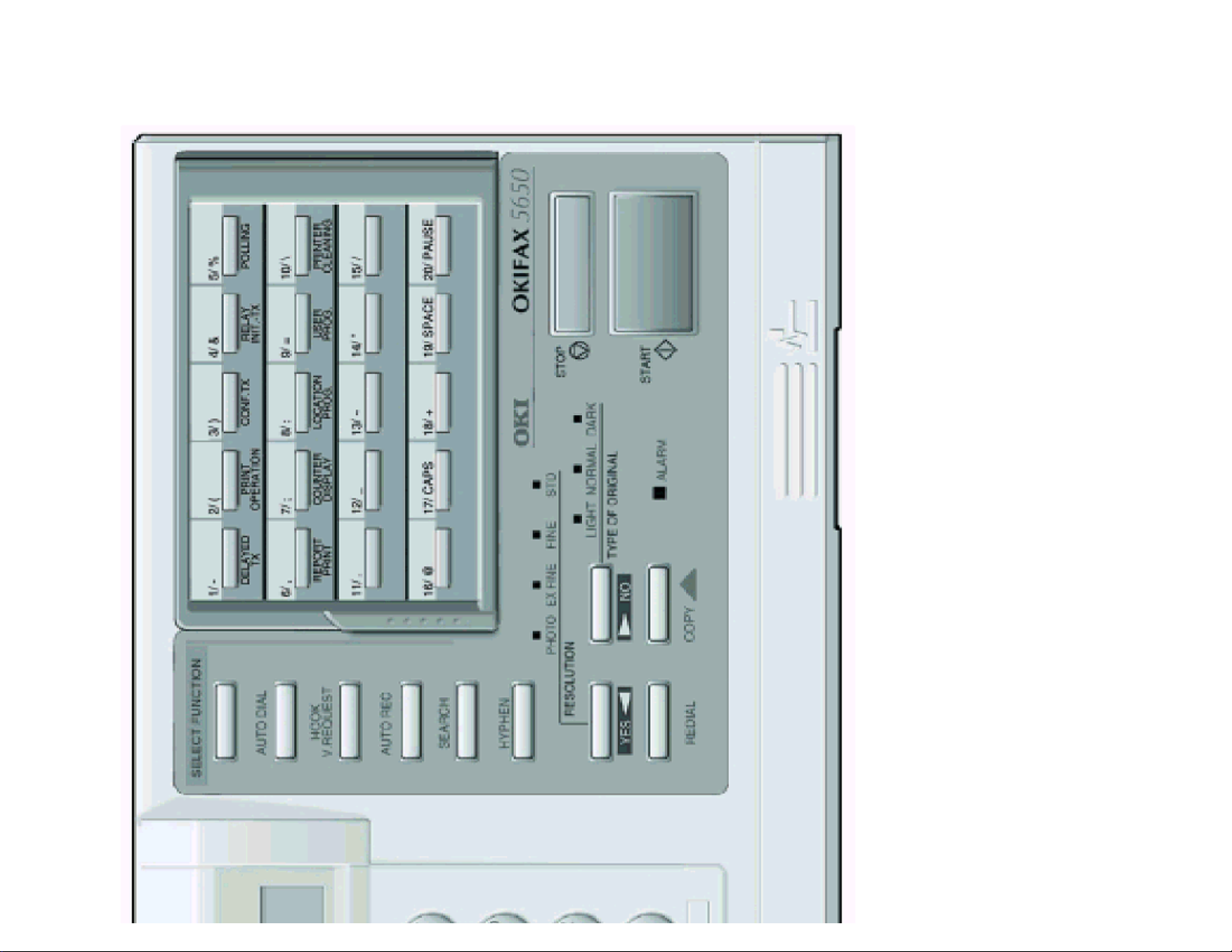
Figure 1.4.1 shows the general appearance. Figure 1.4.2 shows the control panel.
General Appearance of the OKIFAX 5650
Chapter 1 General Information
Page: 5
Control Panel

Copyright 2000, Oki Data, Division of OKI America, Inc. All rights reserved. See the Oki Data Business Partner Exchange
(BPX) for any updates to this material. (http://bpx.okidata.com)

Service Guide OKIFAX 5650
1.5 Basic Performance Specifications
Note:
TF: Technical function setting
FP: Function program setting
OT: One-touch key pressed
F: SELECT FUNCTION key pressed
Table 1.5.1 (1/8) Basic Performance Specifications
Table 1.5.1 (2/8) Basic Performance Specifications
Table 1.5.1 (3/8) Basic Performance Specifications
Table 1.5.1 (4/8) Basic Performance Specifications
Table 1.5.1 (5/8) Basic Performance Specifications
Table 1.5.1 (6/8) Basic Performance Specifications
Table 1.5.1 (7/8) Basic Performance Specifications
Table 1.5.1 (8/8) Basic Performance Specifications
Chapter 1 General Information
Page: 6
Copyright 2000, Oki Data, Division of OKI America, Inc. All rights reserved. See the Oki Data Business Partner Exchange
(BPX) for any updates to this material. (http://bpx.okidata.com)
Service Guide OKIFAX 5650
Table 1.5.1 (1/8) Basic Performance Specifications
No. Item Specifications
1
Applicable line 1) Public switched telephone network (PSTN)
Chapter 1 General Information
2) Private branch exchange (PBX) (OT9+2)
Page: 7
2
Line interface
1) Impedance 600 Ohms balanced
Note: Impedance may differ by the requirement of PTT.
2) Sending power level 0 dBm to -15 dBm range
(Adjustable in 1 dB steps. Technical Setup No. 22)
3) Receiving power level 0 dBm to -40 dBm or -6 dBm to -46 dBm
(In case of V.34 TX/RX, -3 to -43 dBm
3
Type of document to be
transmitted
1) Width Max. 216 mm (NA Letter)
Min: 148 mm (ISO A5 size)
Note: Effective reading width is NA Letter 215 mm)
2) Length Min. 128 mm (5 inches)
Max. 356 mm (14 inches)
Long document detection: 380 mm, or 150 mm
* TF + 10 (To enable or disable the long document scanning)
3) Thickness Based on common bond paper
a) 0.08 to 0.13 mm for multiple page feeding
b) 0.06 to 0.15 mm for single page feeding
4) Shape Rectangular
5) Opacity Documents allowing less than 40% of the scanner source light
to pass through them.

Copyright 2000, Oki Data, Division of OKI America, Inc. All rights reserved. See the Oki Data Business Partner Exchange
(BPX) for any updates to this material. (http://bpx.okidata.com)
Service Guide OKIFAX 5650
Table 1.5.1 (2/8) Basic Performance Specifications
No. Item Specifications
4
Effective reading width
Chapter 1 General Information
Page: 8
Document width Communication
ISO A4 (210 mm)
Mode/Paper width
G3/A4 208 mm for TX
[INTL/FTZ]
NA letter (216 mm)
G3/A4 215.4 mm for TX
[US/CANADA]
NA legal (216 mm)
G3/A4 215.1 mm for TX
[US/CANADA]
Note: Local copy: Printable reading width in a local copy mode
No. Item Specifications
5
Automatic document
Max. 30 documents: NA Letter or A4 (20 lb./75gm)
Effective reading width Copy size
202.8 mm for local copy
211.3 mm for local copy
211.2 mm for local copy
feeder (ADF)
Max. 15 documents: NA or A4 (16 to 28/60 to 105gm)
Documents shall be placed face down on ADF stacker. The first
sheet will be fed first in the feeder and will exit face down in the
document stacker.
6
Document skew Max. 2.6 mm skew over a document of A4 length. For a
document longer than A4 length, occurrence of skew exceeding
2.6 mm over any A4 length is 0.5% or less.
7
Document jam detection 1) Transmission will stop and line disconnection will occur when
the end of a document is not detected within 356 mm after
scanning begins (except for the long document scanning. TF +
10)
A4
Letter
Legal
2) A jam will also be declared if the document does not reach
the scanning position within 5 seconds after the start of a

document feed.
Note: When a jam is detected during message transmission
from the feeder, the machine will stop scanning and disconnect
the line, but its receiving capability will remain valid.
8
Document jam removal Manual release
Copyright 2000, Oki Data, Division of OKI America, Inc. All rights reserved. See the Oki Data Business Partner Exchange
(BPX) for any updates to this material. (http://bpx.okidata.com)

Service Guide OKIFAX 5650
Table 1.5.1 (3/8) Basic Performance Specifications
No. Item Specifications
9
Recording paper or sheet For the first or second recording paper cassette:
Chapter 1 General Information
1) Type: Plain paper cut (Bond paper: Xerox 4200 type or
equivalent)
2) Size: ISO A4 210 mm x 297 mm
NA Letter 215.9 mm x 279.4 mm / 8.5 inch x 11 inch
NA Legal 14: 215.9 mm x 355.6 mm / 8.5 inch x 13 inch
3) Weight: 16 lbs to 24 lbs/60 to 90 gm base weight
Base weight is defined as the weight of 500 sheets
of 431.8 mm (17 inch) by 558.8 mm (22 inch) or 1 sheet size
1000 mm by 1000 mm.
4) Thickness: 0.08 mm to 0.12 mm
5) Condition: New paper
For the manual loading feeder
1) Type: Plain paper, transparency for overhead projector,
colored paper, printer paper
Page: 9
10
Recording paper cassette
first cassette
second cassette
2) Size: A4/NA Letter/NA Legal
3) Weight, thickness and condition: Same as above
Note: One single sheet should be loaded on the manual paper
feeder for one occasion.
For best results use Oki Data recommended papers
1) Xerox 4200 (20 - lb/75 gm base weight paper)
2) L-type paper for photo-printers
Up to 250 sheets/cassette
(Oki Data recommended paper)
Up to 500 sheets/cassette
 Loading...