

OKEYNET OER-305 User Manual

1 WAN + 4 Ports Ethernet SOHO Router P 0
OKEYNET
OER-305
1 WAN Port + 4 Port Ethernet
IP Sharing Router
User Manual

1 WAN + 4 Ports Ethernet SOHO Router P 1
Copyright
The contents of this publication may not be reproduced in any part or as a whole, stored, transcribed in an
information retrieval system, translated into any language, or transmitted in any form or by any means,
mechanical, magnetic, electronic, optical, photocopying, manual, or otherwise, without the prior written
permission.
Trademarks
All product, company, brand names are trademarks or registered trademarks of their respective companies.
They are used for identification purpose only. Specifications are subject to be changed without prior notice.
FCC Interference Statement
This equipment has been tested and found to comply with the limits for a Class B digital device pursuant to Part
15 of the FCC Rules. These limits are designed to provide reasonable protection against radio interference in a
commercial environment. This equipment can generate, use and radiate radio frequency energy and, if not
installed and used in accordance with the instructions in this manual, may cause harmful interference to radio
communications. Operation of this equipment in a residential area is likely to cause interference, in which case
the user, at his own expense, will be required to take whatever measures are necessary to correct the
interference.
CE Declaration of Conformity
This equipment complies with the requirements relating to electromagnetic compatibility, EN 55022/A1 Class B,
and EN 50082-1. This meets the essential protection requirements of the European Council Directive
89/336/EEC on the approximation of the laws of the member states relation to electromagnetic compatibility.
Copyright© 2000 - 2003, xxxxx . All Right Reserved.

1 WAN + 4 Ports Ethernet SOHO Router P 2
CONTENTS
CHAPTER 1 INTRODUCTION........................................................................................................ 4
1.1 FEATURES ..................................................................................................................................... 4
1.2 PACKAGE CONTENTS..................................................................................................................... 5
1.3 SYSTEM REQUIREMENT................................................................................................................. 6
1.4 PANEL DESCRIPTION .....................................................................................................................6
1.4.1 Front Panel........................................................................................................................... 6
1.4.2 Rear Panel ............................................................................................................................ 7
CHAPTER 2 INSTALLATION..........................................................................................................8
2.1 HARDWARE CONNECTION TO WAN .............................................................................................. 8
2.2 HARDWARE CONNECTION TO LAN ............................................................................................... 8
2.3 NETWORK SETTING IN ADMINISTRATOR’S COMPUTER .................................................................. 9
CHAPTER 3 DEVICE ADMINISTRATION ................................................................................. 12
3.1 WEB BASED CONFIGURATION .....................................................................................................12
3.1.1 Device Information ............................................................................................................. 13
3.1.2 Administration ....................................................................................................................13
3.1.3 EZ Setup - WAN ..................................................................................................................15
3.1.4 EZ Setup - LAN ................................................................................................................... 19
3.2 TELNET CONFIGURATION ............................................................................................................ 23
CHAPTER 4 FIREWALL AND ADVANCED FUNCTIONS ....................................................... 24
4.1
ACCESS CONTROL....................................................................................................................... 24
4.2 MAC FILTER............................................................................................................................... 25
4.3 SERVICE TIME ALLOCATION ........................................................................................................ 26
4.4 LAN PC MANAGEMENT ............................................................................................................. 27
4.5 URL KEYWORD BLOCKING ........................................................................................................28
4.6
VIRTUAL SERVER ........................................................................................................................ 29
4.7 DMZ........................................................................................................................................... 30
4.8 MULTIPLE DMZ HOST ................................................................................................................ 31
4.9 AUTO 2-WAY APPLICATIONS. ......................................................................................................34
4.10 . DYNAMIC DNS ....................................................................................................................... 35
4.11 . UPNP (UNIVERSAL PLUG AND PLAY)...................................................................................... 36
CHAPTER 5 TROUBLESHOOTING ............................................................................................ 38
5.1
COMMON PROBLEMS & SOLUTIONS ........................................................................................... 38
5.2 FREQUENTLY ASKED QUESTIONS................................................................................................39

1 WAN + 4 Ports Ethernet SOHO Router P 3
1 WAN + 4 Ports Ethernet SOHO Router P 4
Chapter 1 Introduction
Congratulations on your purchase of this outstanding SOHO Router. This product is the perfect choice to
connect a group of PCs to a high-speed Broadband Internet connection or to an Ethernet based Backbone
(ETTH/ETTB: Ethernet To The Home/Building). Configurable as a DHCP server, this product is the only
externally recognized server device on your local area network (LAN). Thus even a non-technical person will
easily configure it to meet the versatile applications.
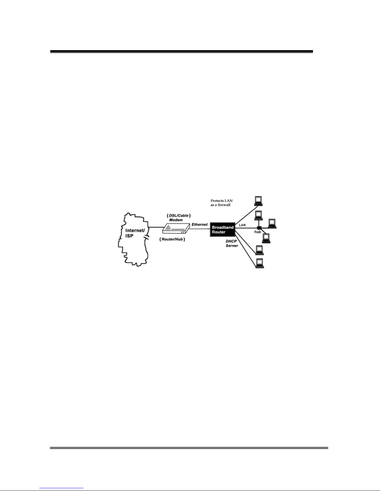
This product does not only provide a complete solution to share the Internet bandwidth, it also serves as an
Internet Firewall to protect your LAN data from being accessed by outside intruder/hacker (Figure 1-1). Since
all incoming data packets have been inspected/analyzed, all unwanted packet may be filtered-out and be
recorded as an intrusion event. This SOHO Router can also be configured to block some internal LAN user’s
access to the Internet for management purpose.
Figure 1-1 Secure Internet Access via Cable/DSL Modem.
1.1 Features
Connects to 10/100M Broadband (cable or DSL) modem or Ethernet backbone for Internet
access.
Multiple WAN connection type:
Static IP : for xDSL lease line or router-to-router interconnect.
DHCP client : for most cable modem service.
PPPoE : for Dial-up xDSL service,
PPTP client : for Layer2-VPN application or certain xDSL service in Europe
Equipped with a 4-port 10/100M switched Hub (w/ auto MDIX) for LAN users.
DHCP Server/ DNS proxy support .
All the networked computers in LAN can retrieve TCP/IP setting (IP address, subnet mask, gateway,
DNS,IP…) automatically from this device.

1 WAN + 4 Ports Ethernet SOHO Router P 5
Simultaneously act as both DHCP Server on the LAN and a DHCP Client on the WAN for most
easy application.
Connects multiple LAN PCs to the Internet with only one dynamic-assigned IP address (NAT
mode) or a range of legal IP address (NAT/Routing mode)
Web-based Configuring
Configurable through any networked computer’s web browsers using Internet Explorer or Netscape
browser.
Allow/Deny Web administration through WAN connection by remote Web browser.
Support Telnet / Console administration from a networked computer in LAN.
Firewall capability to protect LAN PCs from outside intruder access/attack.
Avoid unwanted packet from WAN and provide a system event log to record intrusion information.
(date/time, source/destination IP address & port …)
Access right of LAN users
Administrator can arrange interior LAN user’s access right to Internet by MAC address,IP address,
TCP/IP port number, URL keywords and a pre-defined time table.
Virtual Server (Port forwarding) function
Internet servers (WWW, FTP, E-mail …) in LAN could be virtually exposed to WAN for outside Internet
user. This is a useful and secure network deployment for Internet servers.
DMZ (De-Militarized Zone) Host
Administrator can totally expose a host PC in LAN to the Internet without any firewall protection
mechanism. This option allows the two-way communication between the local host PC and remote
Internet node. (ex. bi-directional games, video/audio conference, P2P services …)
Multi DMZ Host support
In static IP configuration with a range of legal IP address, Administrator could totally expose more host
PCs in LAN to the Internet according to LAN/WAN IP address mapping.
Auto 2-way Special Applications
Provide an automatic mechanism to support some specific application which need one or many
incoming ports when they connect with application servers in Internet. (Like Microsoft Game Zone,
Battle.net, eDonkey/eMuls …)
Dynamic DNS
Via WWW.DynDns.org
DNS service provider, your registered domain name could be updated
automatically whenever system’s WAN IP is changed.
UPnP (Universal Plug and Plag) supported
1.2 Package Contents
One SOHO router unit
1 WAN + 4 Ports Ethernet SOHO Router P 6
One CD-ROM (manual/utility)
One power adapter
One CAT-5 UTP cable
1.3 System Requirement
One Ethernet based broadband Internet connection (like cable/ADSL modem or equivalent )
One PC with a NIC card, and installed TCP/IP protocol stack.
Microsoft Internet Explorer 5 or later (Netscape V6/7 or later) web browser.
All TCP/IP networked computers in LAN.
1.4 Panel Description
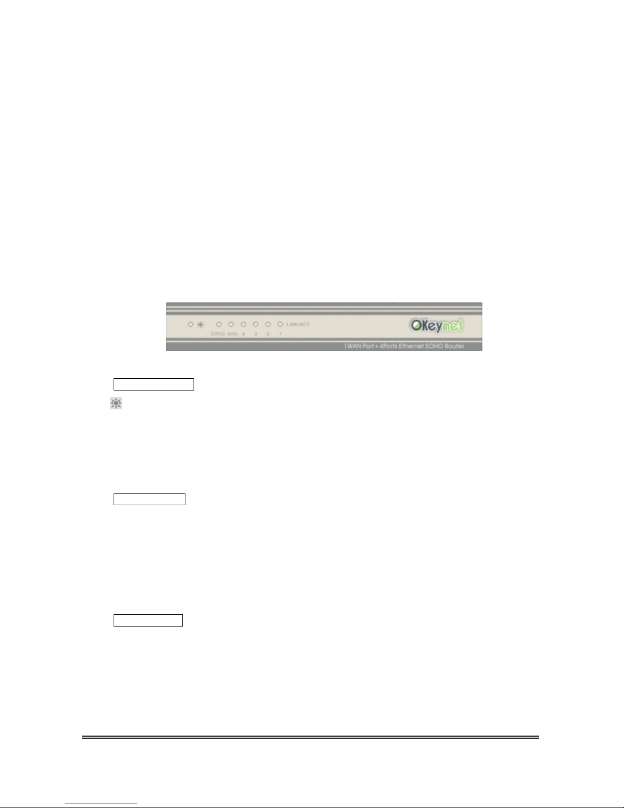
1.4.1 Front Panel
Device Indicators
PWR (power): The Power LED illuminates whenever power is good.
Status (ready): The Status LED blink once per second when it is working normally, or it will
blink faster or be off in case the SOHO Router is
something wrong.
WAN Indicators
Lnk/Act Lnk (link):ON means WAN (ADSL/Cable modem) is connected correctly.
Act (activity): Blinking means data communication is happened.
10/100 Indicates 10 or 100Mbps wire speed corresponding to WAN port. (On is 100Mps)
LAN Indicators
Lnk/Act Lnk (link):ON means LAN PC/device is connected correctly to SOHO Router.
Act (activity): Blinking means data communication is happened.
10/100 Indicates 10 or 100Mbps wire speed corresponding to each port. (On is 100Mps)

1 WAN + 4 Ports Ethernet SOHO Router P 7
1.4.2 Rear Panel
Reset It is the factory default button. Hold it down continuously more than 5 seconds to reset
the hardware setting into factory default. The LAN IP becomes default
192.168.8.1.
Power Where you will plug the Power adapter.
1 WAN + 4 Ports Ethernet SOHO Router P 8
Chapter 2 Installation
Attaching the power cord into PWR inlet first and follow below sections to setup WAN/LAN connection.
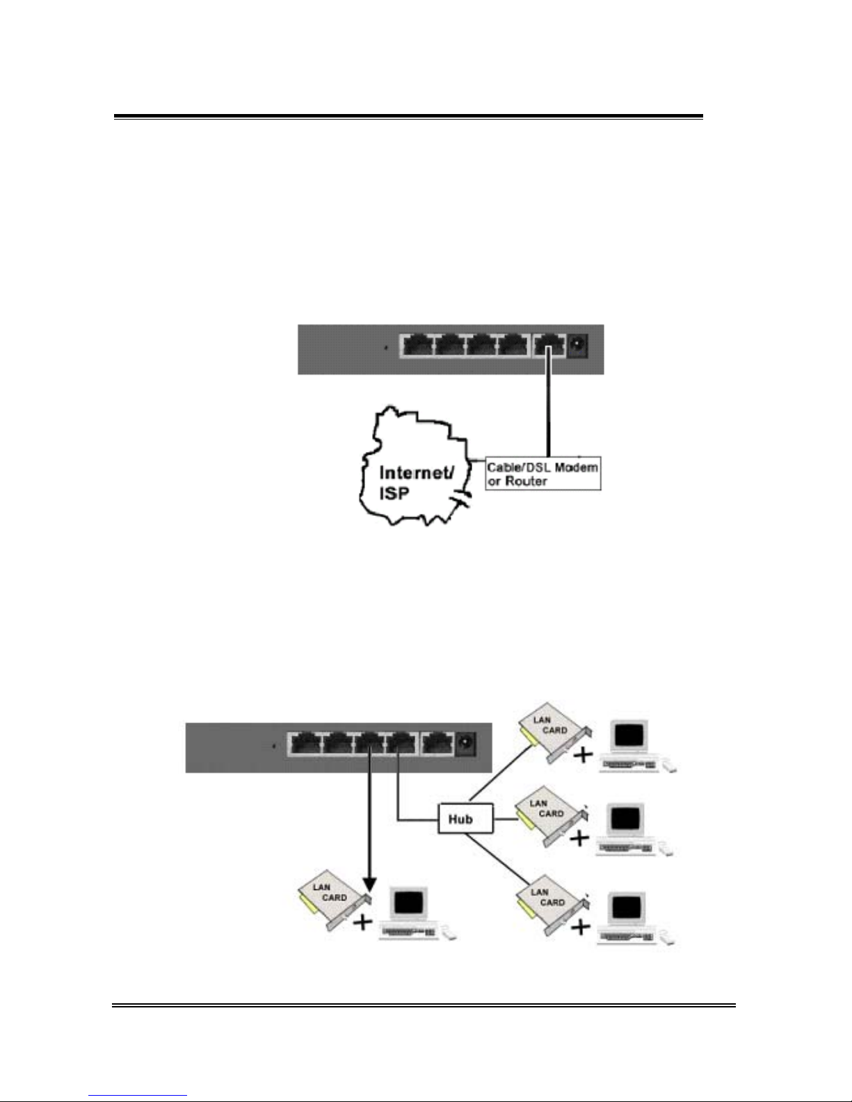
2.1 Hardware Connection to WAN
Connect the network cable from the Cable/ DSL modem to the WAN port of the SOHO Router (Figure 2-1). If
the Link/Act LED is always off, please check the power feeding and the connection cable between the
Cable/DSL modem and WAN port .
Figure 2-1 The hardware connection of WAN interface for SOHO Router.
2.2 Hardware Connection to LAN
Connect the network cable from your computer’s Ethernet port to one of SOHO Router’s 4 LAN ports (Figure
2-2). If it is correctly connected, the responding Link/Act LED will be on.
Figure 2-2 The hardware connection of LAN interface for SOHO Router.
1 WAN + 4 Ports Ethernet SOHO Router P 9
Since all the WAN and 4 LAN ports have the auto crossover capability. You could use the flat RJ-45 cable or
the crossover cable as you wish (please refer to the Appendix C for pin assignment).
Once both WAN/LAN are connected successfully, please hold down the reset button continuously for 5
seconds to make sure SOHO Router is on factory default condition now.
2.3 Network Setting in Administrator’s computer
In order to configure the router with a networked PC in LAN, it is necessary for administrator to have an
accurate network setting PC, then the communication between router and administrator‘s PC could be possible.
The following description assumes router is on factory default condition. (If not, please hold the reset button
down for more than 5 seconds). Router’s LAN IP will become 192.168.8.1 and the DHCP server for LAN user is
on (offered IP range from 192.168.8.17 to 192.168.8.128 by default).
Follow the procedures to set your computer as a DHCP Client. (If the fixed IP mode for administrator’s
computer is desired, please refer to Appendix D.)
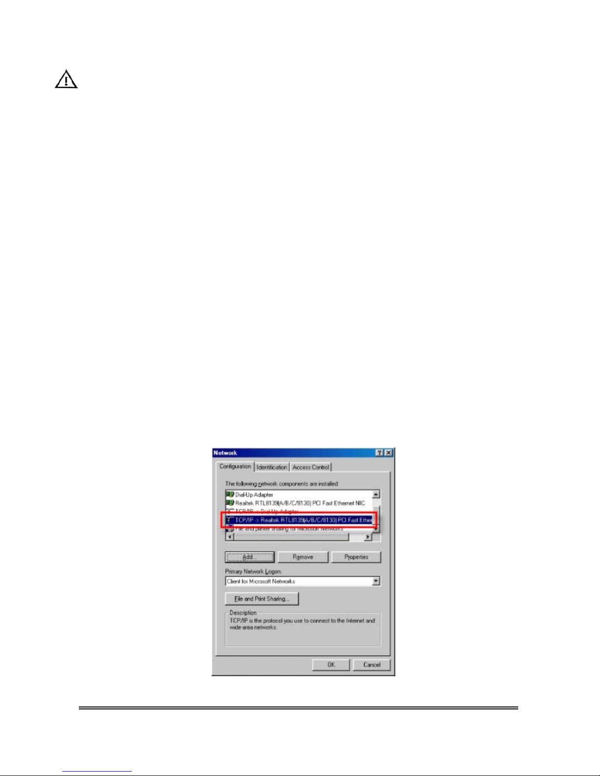
Step1:
Click Start button, select Settings, and then choose Control Panel. Double click Network icon.
Choose configuration item. Select the TCP/IP protocol option, which is associated with your network
card/adapter. (To install TCP/IP protocol first.)

1 WAN + 4 Ports Ethernet SOHO Router P 10
Step2:
Click the Properties button, and then press the IP Address tab. Select Obtain an IP address automatically.
Step3:
Press [ok] to continue.
System may request to restart.
After restart, the connection between router & window is established. Please check it as follows.
Windows 9x/Me :
Start ->control panel->Run
Type “winicfg”, and then press [ok] button.
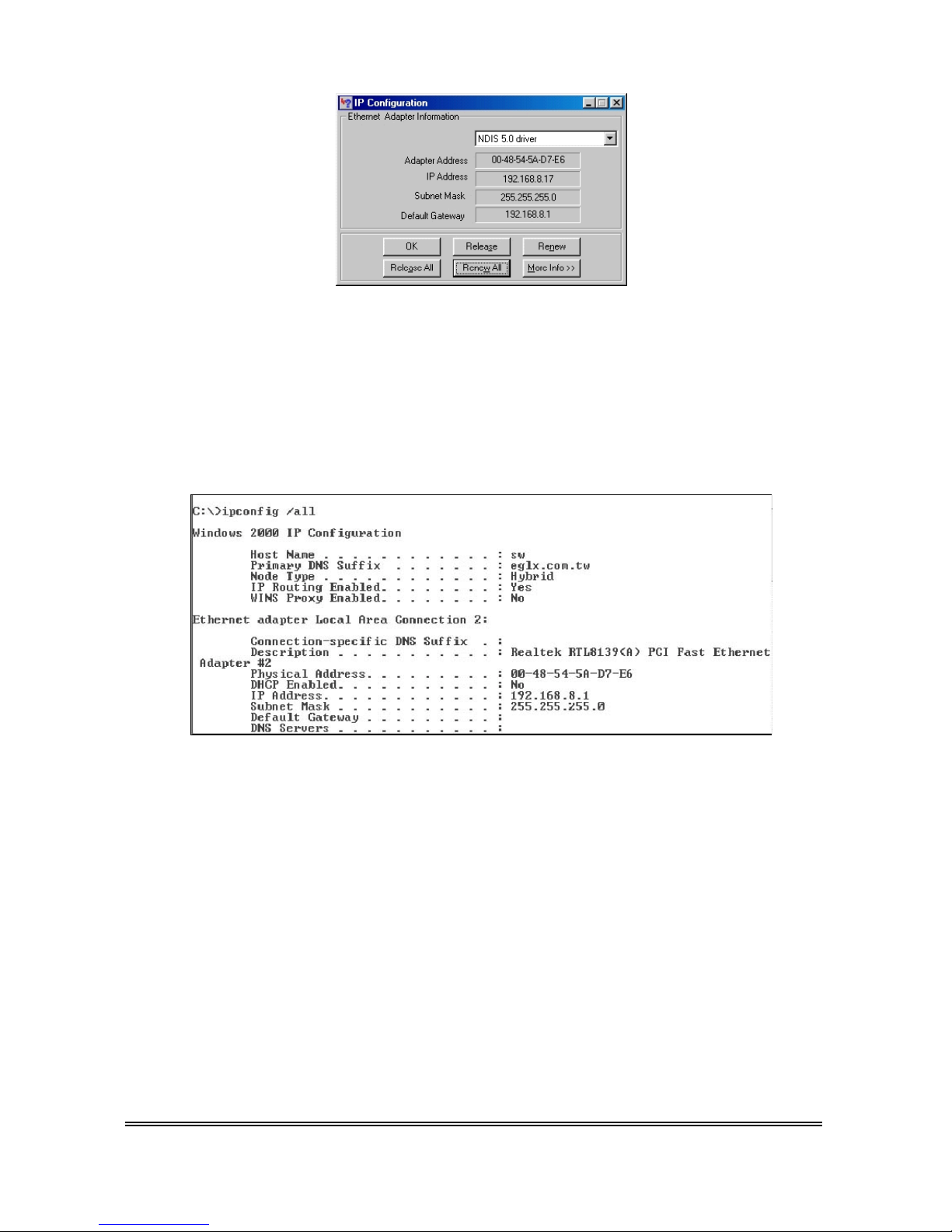
1 WAN + 4 Ports Ethernet SOHO Router P 11
All Ethernet adapter information is showed in this window.
Check if you get an IP address like 192.168.8.x and the default gateway is 192.168.8.1.
Windows XP/2000/NT4 :
Please change to MS-DOS command window, and type “ipconfig /all” to check Ethernet adapter information.
All Ethernet adapter information is showed in this window.
Check if you get an IP address like 192.16.8.x and the default gateway is the default IP of router.
If all the steps are finished, the network should be working now. In case there is something wrong, please refer
to Chapter 5 for troubleshooting.
1 WAN + 4 Ports Ethernet SOHO Router P 12
Chapter 3 Device Administration
SOHO Router could be configured via Web browser, telnetl. Administrator can choose either one of methods to
perform device administration.
No matter which method to use, this administration only allows one login session at a moment. This is due to
the consideration of system database consistency. If there is any other one intending to login, none could
succeed to login at that time. SOHO Router will pop-up an alert message.
Similarly the following description assumes SOHO Router is on factory default condition.
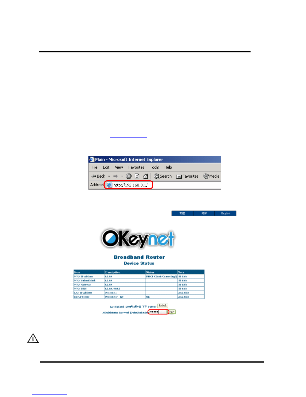
3.1 Web Based Configuration
Open the web browser and type http://192.168.8.1 in the browser’s address box. This IP address is SOHO
Router’s LAN interface address.
One moment later, the main page is shown as below.
This page is not protected by any password, it is used to provide all LAN users to inquire SOHO Router device
status at any time.
Type in the default Administrator password ”admin”. Then press ENTER to login.
1 WAN + 4 Ports Ethernet SOHO Router P 13
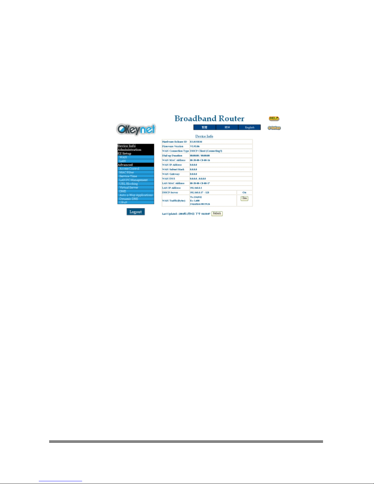
3.1.1 Device Information
After login, the first page shown is the Device Information of router.
In this page, it show the detailed status of SOHO Router, and display the current WAN’s information
about dial-up duration and traffic (bytes count)
You can press the [Clear] button to clear the WAN traffic counter. And you can press the [Refresh]
button to refresh the last update.
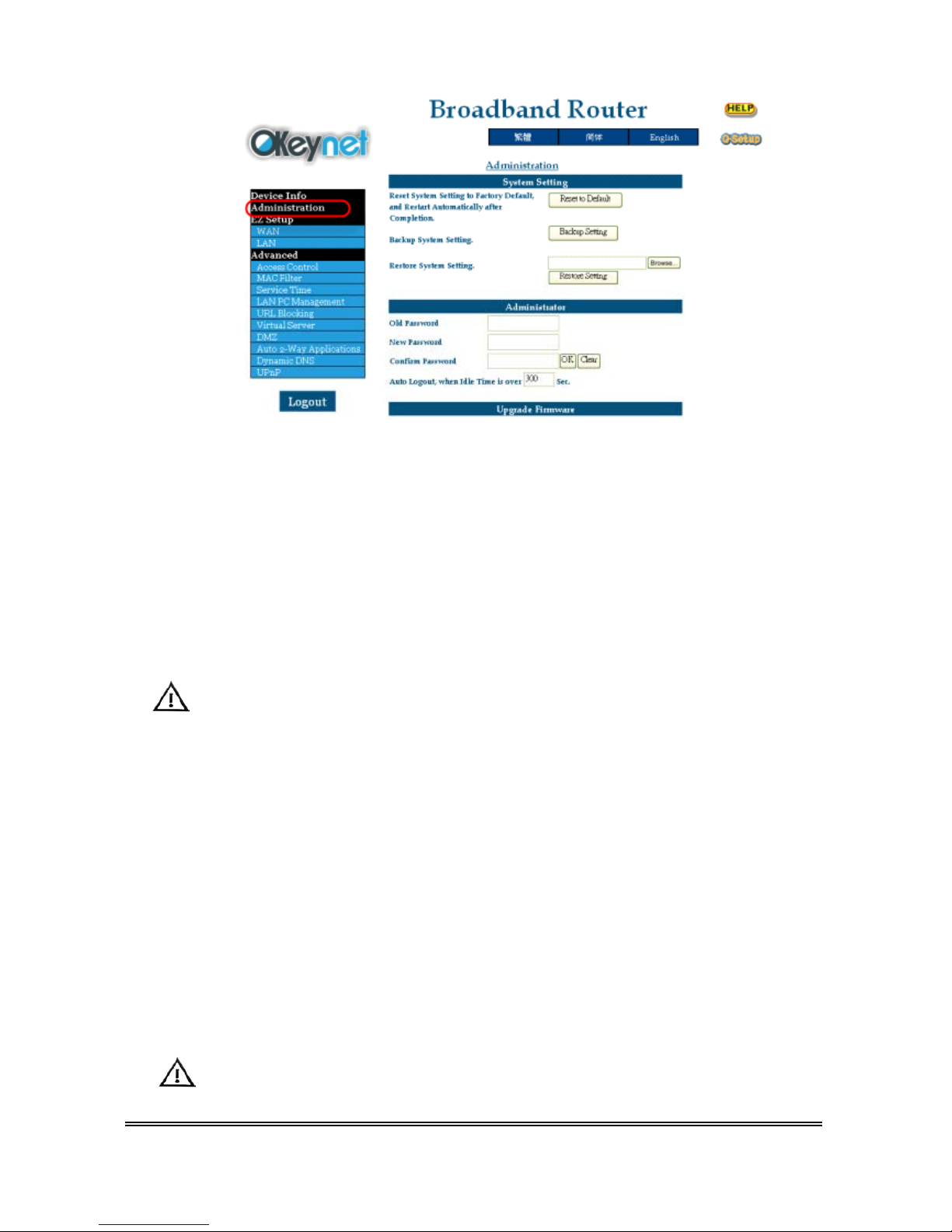
3.1.2 Administration
Press the Administration option on the left frame of this page to assign/change the setting.
1 WAN + 4 Ports Ethernet SOHO Router P 14
System Setting:
[Reset to Default]: Reset System Setting to Factory Default, and Restart Automatically after
Completion.
[Backup Setting]: Save the current system setting into a file in order to restore SOHO Router
setting when needed in the future.
[Restore Setting]: Restore the previous system setting from a saved backup file. When
completion, SOHO Router restart automatically.
SOHO Router allow system setting Backup / Restore only when both firmware are the same
Version. Otherwise SOHO Router will deny the Restore operation for reliability consideration.
Administrator:
[Reset to Default]: Type in your old password and new password and confirm it. Then
press OK to send this request.
[Auto Logout]: Whenever administrator is idle more than a specified time (default
is 300 seconds), SOHO Router will logout automatically for
security.
Upgrade Firmware:
Press [browse] to choose the correct firmware upgrade file (*.upg). While a file has been selected,
click [Go] to send this request. SOHO Router’s firmware will be upgraded immediately.
After a moment (about 4~5 second), SOHO Router will restart automatically.
 Loading...