

Page 1
OAC 2221
MOBILES KLIMAGERÄT // PORTABLE AIR COndITIOnER
dE
GEBRAUCHSANWEISUNG 3
En
USER MANUAL 18
IM_OAC2221_161201_V04
www.ok-online.com
Imtron GmbH
Wankelstraße 5
85046 Ingolstadt
Germany
www.imtron.eu
9
10
SHORT
CUT
TIMER
ON
TIMER
OFF
TEMP
20
FAN
Set Temp.
Auto
Timer OnTimer Off
11 12
ON/OFF
SHORT
CUT
TIMER
ON
TIMER
MODE
FAN
TEMP
20
FAN
Set Temp.
Auto
Cool
Dry
Heat
Fan
Auto
Timer OnTimer Off
13
14
15
2
hrs.
IM_OAC2221_161201_V04_HR.indb 1 1/12/16 4:31 PM
Page 2
1
N
1
1
2
Q O N
2
2
min
30 cm
max
120 cm
3
1
1
2
2
R O N
4
5
ON/OFF
SHORT
CUT
TIMER
ON
TIMER
MODE
FAN
TEMP
20
FAN
Set Temp.
Auto
Cool
Dry
Heat
Fan
Auto
Timer OnTimer Off
6
7
ON/OFF
SHORT
CUT
TIMER
ON
TIMER
OFF
MODE
FAN
TEMP
SLEEP LED
20
FAN
Set Temp.
Auto
Cool
Dry
Heat
Fan
Auto
Timer OnTimer Off
8
ON/OFF
SHORT
CUT
TIMER
ON
TIMER
OFF
MODE
FAN
TEMP
SLEEP LED
20
FAN
Set Temp.
Auto
Cool
Dry
Heat
Fan
Auto
Timer OnTimer Off
ON/OFF
SHORT
CUT
TIMER
ON
TIMER
OFF
MODE
FAN
TEMP
SLEEP LED
20
FAN
Set Temp.
Auto
Cool
Dry
Heat
Fan
Auto
Timer OnTimer Off
A1 M M1A2
A3
A4
M2
M3
M10
M11
M12
M9
M8
M5
M6
M7
M4
A9
B
C
D
E
F
G
H
I
J
L
N O P Q SR T U V
K
A11
A10
A5
A6A7A8
A
IM_OAC2221_161201_V04_HR.indb 2 1/12/16 4:31 PM
Page 3

3
DE
HERZLICHEN GLÜCKWUNSCH!
Vielen Dank, dass Sie sich für ein Produkt von ok. entschieden haben. Bitte lesen Sie diese Anleitung
sorgfältig durch und bewahren Sie sie für späteren Gebrauch auf.
WICHTIGE SICHERHEITSANWEISUNGEN. BITTE AUFMERKSAM DURCHLESEN UND FÜR
SPÄTEREN GEBRAUCH AUFBEWAHREN.
1.
Wichtige Sicherheitsanweisungen! Sorgfältig lesen und für
den weiteren Gebrauch aufbewahren! Achten Sie besonders
auf alle Abbildungen auf der Illustrationsseite!
2. Dieses Produkt kann von Kindern ab 8 Jahren und darüber
sowie von Personen mit verringerten physischen, sensorischen
oder mentalen Fähigkeiten oder Mangel an Erfahrung und
Wissen benutzt werden, wenn sie beaufsichtigt oder bezüglich
des sicheren Gebrauchs des Produktes unterwiesen wurden
und die daraus resultierenden Gefahren verstehen.
3. Kinder dürfen nicht mit dem Produkt spielen.
4. Reinigung und Benutzer-Wartung dürfen nicht von Kindern
ohne Beaufsichtigung durchgeführt werden.
5. Wenn die Netzanschlussleitung dieses Produktes beschädigt
wird, muss sie durch den Hersteller oder seinen Kundendienst
oder eine ähnlich qualizierte Person ersetzt werden, um
Gefährdungen zu vermeiden.
6. Halten Sie den in den technischen Daten angegebenen
minimalen Umgebungsabstand um das Produkt ein und
sorgen Sie für ausreichende Luftzirkulation.
7. Platzieren Sie das Produkt nicht in direktem Sonnenlicht oder in
der Nähe von Hitzequellen, da dies den Kühlprozess behindert.
8. Stellen Sie das Produkt auf eine stabile und ebene Fläche.
9. Kippen Sie das Produkt nicht über einen Winkel von 45°, um
Schäden am Kältemittelkreislauf zu vermeiden.
10. Das Produkt muss entsprechend den nationalen
Installationsvorschriften installiert werden.
11. Installieren Sie das Produkt nicht an einem Ort mit hoher
Luftfeuchtigkeit oder wo Spritzwasser wahrscheinlich ist (z.B.
Waschküche).
12. Verwenden Sie das Produkt nicht in explosiven Umgebungen,
entstehend aus einer entammbaren Mischung aus Luft,
brennbaren Dämpfen, Dünsten, Nebeln oder Staub.
IM_OAC2221_161201_V04_HR.indb 3 1/12/16 4:31 PM
Page 4

4
DE
13. Verwenden Sie keine Aerosol-Sprühdosen in der Nähe des
Produkts.
14. Das Produkt ist nur für den Gebrauch in Innenräumen
bestimmt.
15. Positionieren Sie das Produkt so, dass der Netzstecker
zugänglich ist.
16. Beachten Sie die minimale und maximale Umgebungstempe-
ratur für den Betrieb in den technischen Daten.
17. Nehmen Sie keinerlei Veränderungen an dem Produkt vor.
Verwenden Sie nur Aufsätze und Zubehörteile, die vom
Hersteller empfohlen werden.
18. Stellen Sie vor dem Anschluss an die Stromversorgung sicher,
dass die auf dem Typenschild angegebene Netzspannung mit
der Ihrer Stromversorgung übereinstimmt.
19. Benutzen Sie das Produkt nicht, wenn der Stecker oder das
Kabel beschädigt ist, wenn das Produkt nicht ordnungsgemäß
funktioniert oder anderweitig beschädigt ist.
20. Schützen Sie die Anschlussleitung gegen Beschädigungen.
Lassen Sie diese nicht über scharfe Kanten hängen und
knicken Sie diese nicht. Halten Sie die Anschlussleitung fern
von heißen Oberächen und stellen Sie sicher, dass niemand
darüber stolpern kann.
21. Führen Sie keine Finger oder Gegenstände in das Innere des
Produktes ein und blockieren Sie nie die Lüftungsönungen.
22. Schützen Sie das Produkt vor Hitze. Stellen Sie das Produkt
nicht in der unmittelbaren Nähe von Hitzequellen wie z. B.
Herden oder Heiz Produkten auf.
23. Verbinden Sie das Produkt nicht mit Verlängerungskabeln
oder Mehrfachsteckdosenleisten.
24. Warnung! Schalten Sie das Produkt aus und trennen Sie die-
ses vor dem Austausch von Zubehörteilen, vor Reinigungsarbeiten und bei Nichtgebrauch von der Stromversorgung.
25. Warnung - Stromschlaggefahr! Schützen Sie elektrische
Teile gegen Feuchtigkeit. Tauchen Sie diese nie in Wasser
oder andere Flüssigkeiten, um einen elektrischen Schlag zu
vermeiden. Halten Sie das Produkt nie unter ießendes Wasser.
Beachten Sie die Anweisungen für Reinigung und Pege.
IM_OAC2221_161201_V04_HR.indb 4 1/12/16 4:31 PM
Page 5

5
DE
26. Nehmen Sie das Produkt nicht mit feuchten Händen, oder
auf nassem Untergrund stehend in Betrieb. Fassen Sie den
Netzstecker nie mit nassen oder feuchten Händen an.
27. Dieses Produkt entspricht der Schutzklasse I und muss daher
an den Schutzleiter angeschlossen werden.
28. Nur in trockenen Innenräumen verwenden.
29. Lesen Sie diese Bedienungsanleitung vor dem ersten Gebrauch des Produktes aufmerksam durch.
Machen Sie sich mit der Nutzung, den Einstellmöglichkeiten und den Funktionen der Schalter
vertraut. Verinnerlichen Sie Sicherheitshinweise und Anweisungen und befolgen Sie diese, um
mögliche Risiken und Gefahren zu vermeiden.
30. Halten Sie Batterien jeder Zeit außer Reichweite von Kindern.
31. Suchen Sie umgehend ärztliche Hilfe auf, wenn Batterien verschluckt wurden.
32. Fassen Sie ausgelaufene Batterien nur mit entsprechendem Schutz an und entsorgen Sie diese
umgehend. Vermeiden Sie den Kontakt mit Batterieüssigkeit, insbesondere von Haut und Augen.
Spülen Sie die betroenen Stellen bei Kontakt mit Augen oder Mund sofort unter ießendem Wasser
ab und suchen Sie umgehend ärztliche Hilfe auf. Waschen Sie betroenen Hautstellen mit reichlich
Wasser und Seife.
33. Reinigen Sie die Kontakte an Batterien und in dem Produkt, bevor Sie diese einsetzen.
34. Verwenden Sie niemals alte mit neuen Batterien, Batterien unterschiedlichen Typs oder von
verschiedenen Herstellern. Wechseln Sie alle Batterien eines Satzes gleichzeitig aus.
35. Benutzen Sie nur Batterien empfohlen für dieses Produkt, siehe technische Daten.
36. Beachten Sie beim Einsetzen von Batterien die Polarität (+ und -). Achten Sie auf entsprechende
Markierungen auf dem Produkt und der Batterie.
37. Nehmen Sie Batterien aus dem Produkt, wenn dieses für längere Zeit nicht benutzt wird.
38. Entfernen Sie erschöpfte Batterien umgehend aus dem Produkt.
39. Versuchen Sie niemals, nicht wieder auadbare Batterien aufzuladen.
40. Setzen Sie Batterien niemals extremen Bedingungen wie Hitze, Kälte oder Feuchtigkeit aus.
41. Zerlegen, önen oder zerkleinern Sie Batterien nicht.
42. Schließen Sie Batterien nicht kurz. Bewahren Sie diese niemals so auf, dass sie sich gegenseitig
kurzschließen oder durch metallische Objekte kurzgeschlossen werden können.
43. Montieren und verwenden Sie das Produkt ausschließlich wie in dieser Anleitung beschrieben.
44. Untersuchen Sie die Wand, an der Sie den Abluftschlauch montieren wollen, bevor Sie damit
anfangen. Stellen Sie sicher, dass sich keine versteckten Objekte wie z. B. Strom, Wasser oder Gas
führende Leitungen an der Montagestelle benden, die vom Bohrer getroen werden könnten.
45. Halten Sie Kinder und Haustiere währen der Montage fern. Diese könnten Kleinteile verschlucken –
Erstickungsgefahr.
46. Verwenden Sie nur geeignete Werkzeuge zur Montage des Produktes.
47. Ziehen Sie alle Schrauben und andere Verbindungen stets gut fest, überdrehen Sie diese aber nicht.
BESTIMMUNGSGEMÄSSE VERWENDUNG
Dieses Klimagerät dient zur Herunterkühlen oder Entfeuchten von Innenräumen. Jegliche anderweitige
Verwendung ist unsachgemäß, kann zu Verletzungen führen und hat den Ausschluss der Haftung des
Herstellers zur Folge. Dieses Produkt ist nicht für kommerziellen Gebrauch geeignet. Es ist nur für die
Nutzung im Haushalt konzipiert.
Die Imtron GmbH übernimmt keine Haftung für Schäden am Produkt, Sachschaden, oder Verletzung
von Personen aufgrund von unachtsamer, unsachgemäßer, falscher oder nicht dem vom Hersteller
angegebenen Zweck entsprechender Verwendung des Produkts.
IM_OAC2221_161201_V04_HR.indb 5 1/12/16 4:31 PM
Page 6
6
DE
BESCHREIBUNG
A. Bedienfeld
1. Anzeige
2. Kontrollleuchten Temperatureinheit °F / °C
3. Kontrollleuchten Lüftergeschwindigkeit HIGH / LOW
4. Wahltaste Lüftergeschwindigkeit FAN
5. Zeitschaltuhr-Einstelltaste TIMER mit Kontrollleuchten
6. Taste erhöhen
7. Ein-/Standby-Taste mit Kontrollleuchte
8. Taste verringern
9. Schlafmodus-Taste SLEEP mit Kontrollleuchte
10. Modus-Wahltaste MODE
11. Modus-Kontrollleuchten
AUTO / FAN / DRY / COOL
B. Lamelle
C. Fernbedienungs-Empfänger
D. Grimulde
E. Oberer Ablauf
F. Rolle
G. Luftlter
H. Luftauslass
I. Lufteinlass
J. Netzkabelschlaufe
K. Netzkabel mit –stecker
L. Unterer Ablauf
M. Fernbedienung
1. Fernbedienungssender
2. Display mit Funktionsanzeigen
3. Vorprogrammierte Taste SHORT CUT
4. Timer-Taste Ein TIMER ON
5. Timer-Taster Aus TIMER OFF
6. Anzeige/Indikator Ein/Aus-Taste LED
7. Batteriefach mit Deckel
8. Schlafmodustaste SLEEP
9. Temperatur erhöhen/verringern
10. Wahlstaste Lüftergeschwindigkeit FAN
11. Moduswahltaste MODE
12. Ein/Aus-Taste ON/OFF
N. Abluftschlauchadapter
O. Abluftschlauch
P. Wandadapter
Q. Wandanschluss
R. Fensterauslassadapter
S. Batterie (LR03/AAA, x 2)
T. Dübel (x 4)
U. Schraube (x 4)
V. Entwässerungsschlauch
VOR DEM ERSTEN GEBRAUCH
• Entfernen Sie das Produkt und Zubehör vorsichtig aus der Originalverpackung. Es empehlt sich,
die Originalverpackung für späteres Verstauen aufzubewahren. Möchten Sie die Originalverpackung
entsorgen, so tun Sie dies nach den geltenden gesetzlichen Bestimmungen. Haben Sie Fragen zur
richtigen Entsorgung, fragen Sie bei Ihrer örtlichen Behörde nach.
• Überprüfen Sie den Verpackungsinhalt auf Vollständigkeit und Beschädigungen. Sollte der
Verpackungsinhalt unvollständig oder sollten Beschädigungen feststellbar sein, kontaktieren Sie
umgehend Ihre Verkaufsstelle.
• Reinigen Sie das Produkt nach dem Auspacken; siehe Abschnitt Reinigung und Pege.
IM_OAC2221_161201_V04_HR.indb 6 1/12/16 4:31 PM
Page 7

7
DE
INSTALLATION
Aufstellort
Beachten Sie folgende Punkte bei der Wahl des Installationsorts:
• Beachten Sie alle Sicherheitshinweise!
• Halten Sie einen Umgebungsabstand in jede Richtung von 30 cm und 100 cm zu anderen
ElektroProdukten ein.
• Halten Sie einen Umgebungsabstand von 50 cm rund um den äußeren Abluftwandauslass und
schützen Sie diesen vor eintretenden Objekten oder Feuchtigkeit.
• Stellen Sie sicher, dass die Wand hinter dem Produkt eine Außenwand und keine Trennwand ist
und dass die Bohrungen sicher und ungehindert von versteckten Objekten in der Wand ausgeführt
werden können.
• Stellen Sie sicher, dass eine geeignete Steckdose in Reichweite ist und diese nach der Installation
erreichbar bleibt.
• Seien Sie sich bewusst, dass sich während des Entfeuchtungs- Vorgangs Wasser im Produkt
ansammelt, welches durchgehend mit dem mitgelieferten Entwässerungsschlauch in einen
geeigneten Behälter oder einen Ablauf abgeführt werden muss.
• Versichern Sie sich, dass keine Hindernisse den Luftstrom blockieren.
Abluftschlauch
Je nach Modus-Einstellung muss der Abluftschlauch montiert bzw. demontiert werden:
• Kühlmodus, Automatikmodus: mit Abluftschlauch
• Lüftermodus, Entfeuchtungsmodus: ohne Abluftschlauch
Wandinstallation (Teile : N, O, P, Q)
Abb.
1
Schrauben Sie den Wandadapter und Abluftschlauchadapter jeweils auf eine Seite des
Abluftschlauchs. Verbinden Sie den Abluftschlauchadapter mit dem Luftauslass des
Produktes.
Abb.
2
Verwenden Sie den Wandanschluss als Schablone, um das Bohrmuster auf die Wand
zu übertragen. Bohren Sie Löcher mit einem geeigneten Elektrowerkzeug. Befreien Sie
die Löcher von Bohrstaub und befestigen Sie den Wandanschluss mit den beiliegenden
Schrauben und Dübeln. Verbinden Sie den Wandadapter mit dem Wandanschluss.
Hinweise:
• Der Abluftschlauch kann auseinandergezogen oder zusammengeschoben werden;
halten Sie die Schlauchlänge für eine optimale Leistung jedoch so kurz wie möglich.
• Verlängern Sie den Abluftschlauch nicht.
• Vermeiden Sie ein Überbiegen.
• Beachten Sie die Hinweise zur Außerbetriebnahme im entsprechenden Abschnitt, falls
Sie das Produkt über längeren Zeitraum nicht verwenden.
Fensterinstallation (Teil: N, O, R)
Abb.
3
Alternativ kann der Abluftschlauch auch an einem geöneten bzw. angekippten
Fenster angebracht werden. Schrauben Sie dazu den Fensterauslassadapter ans
oene Schlauchende. Hinweis: Material zur Anbringung und Abdichtung ist nicht im
Lieferumfang enthalten, sondern muss im Fachhandel bezogen werden.
Entwässerungsschlauch
Abb.
4
Der Entwässerungsschlauch wird benötigt, um Wasser aus dem oberen Ablauf abzuleiten.
1. Schieben Sie den Entwässerungsschlauch so weit wie möglich auf den oberen Ablauf.
2. Führen Sie das andere Ende des Entwässerungsschlauch in einen geeigneten Behälter
oder einen nahegelegenen Ablauf.
Hinweise:
• Abhängig von dem eingestellten Betriebsmodus wird das Wasser nach außen geleitet oder
in einem internen Tank gesammelt. Entwässern Sie das Produkt entsprechend.
• Decken Sie die Abläufe stets ab, wenn sie nicht gebraucht werden.
• Beachten Sie die Hinweise zur Außerbetriebnahme im entsprechenden Abschnitt, falls Sie
das Produkt über längeren Zeitraum nicht verwenden.
IM_OAC2221_161201_V04_HR.indb 7 1/12/16 4:31 PM
Page 8

8
DE
Funktionen
Bedienfeld Fernbedienung Funktion
ON/OFF
Ein oder in Standby schalten
TEMP
Wert erhöhen
TEMP
Wert verringern
MODE
Modus auswählen
FAN
Lüftergeschwindigkeit einstellen
SLEEP
Schlafmodus ein-/ausschalten
TIMER
OFF
TIMER
ON
Einstellung der Zeitschaltuhr Ein/Standby
-
LED
Anzeige und Indikatorleuchten ein/aus
-
SHORT
CUT
Voreingestellten Modus oder Temperatur
auswählen
- Umschalten zwischen °C und °F -Einheiten
IM_OAC2221_161201_V04_HR.indb 8 1/12/16 4:31 PM
Page 9
9
DE
Kontrollleuchten
Bedienfeld Fernbedienung Funktion
Auto
Produkt im Automatikmodus
Cool
Produkt im Kühlmodus
Dry
Produkt im Entfeuchtungsmodus
-
Heat
ohne Funktion
Fan
Produkt im Lüftermodus
FAN
FAN
Lüftergeschwindigkeit hoch
FAN
Lüftergeschwindigkeit niedrig
-
FAN Auto
Lüftergeschwindigkeit Auto
Timer On Auto-Ein-Zeit eingestellt
Timer O Auto-Aus-Zeit eingestellt
- Temperatur wird in Fahrenheit (°F) angezeigt
- Temperatur wird in Celsius (°C) angezeigt
— /
Produkt in Standby /ein
SLEEP
Schlummermodus aktiv
-
Signal wird übertragen
Hinweise:
• Jede Betätigung einer Taste auf dem Bedienfeld und jede erfolgreiche Übertragung der
Fernbedienung wird mit einem akustischen Signal bestätigt.
• Alle Funktionen des Produkts können mit dem Bedienfeld oder der Fernbedienung gesteuert werden,
mit Ausnahme der Anzeigenbeleuchtungs-Taste LED und der SHORTCUT-Taste, welche ausschließlich
auf der Fernbedienung zu nden sind.
IM_OAC2221_161201_V04_HR.indb 9 1/12/16 4:31 PM
Page 10
10
DE
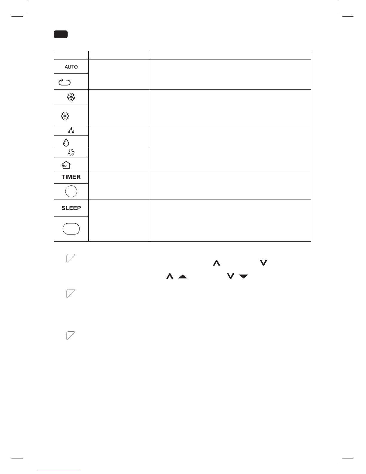
Modi
Modus Anwendung
Automatikmodus
• das Produkt wählt den geeigneten Modus, um die
eingestellte Temperatur zu erreichen
• die Lüftergeschwindigkeit wird automatisch eingestellt
• die Temperatur kann manuell eingestellt werden
Auto
Kühlmodus
• kühlt die Raumtemperatur herunter
• der Kühl-Kompressor startet und stoppt, um die eingestellte
Temperatur zu halten
• die Lüftergeschwindigkeit und die Temperatur können
eingestellt werden
Cool
Entfeuchtungsmodus
• entfeuchtet den Raum mit dem Lüfter
• die Lüftergeschwindigkeit und die Temperatur sind
voreingestellt und können nicht eingestellt werden
Dry
Lüftermodus
• nur Lüfter
• die Lüftergeschwindigkeit kann eingestellt werden
• Temperatureinstellung nicht möglich
Fan
Zeitschaltuhrmodus
• das Produkt schaltet sich zu eingestellten Zeitpunkten ein
und/oder aus
TIME
Schlafmodus
• eingestellte Temperatur wird nach 30 Minuten um 1 °C und
nach weiteren 30 Minuten wiederum um 1 °C erhöht
• Temperatur wird für die folgenden 7 Stunden gehalten,
danach kehrt das Produkt zur eingestellten Temperatur
zurück
• nicht verfügbar während Lüfter- und Entfeuchtungsmodus
SLEEP
Abb.
7
Temperatur einstellen
1. Drücken und halten Sie die beiden Tasten erhöhen
und verringern gemeinsam
länger als drei Sekunden, um zwischen °C und °F zu wechseln.
2. Drücken Sie die Tasten erhöhen / und verringern / einzeln, um die
Temperatur zwischen 17 °C bis 30 °C bzw. 62 °F bis 86 °F einzustellen.
Abb.
8
Lüftergeschwindigkeit einstellen
Betätigen Sie die Wahltaste für die Lüftergeschwindigkeit FAN, um zwischen den
Geschwindigkeiten zu wählen. Die jeweilige Kontrollleuchte auf dem Bedienfeld und der
Fernbedienung zeigen die momentane Einstellung an.
Hinweis:
Es gibt keine Kontrollleuchte am Bedienfeld für die automatische Geschwindigkeitseinstellung.
Abb.
9
Lamellen einstellen
Stellen Sie die Lamellen manuell so ein, dass der Luftstrom in eine beliebige Richtung geleitet
wird. Dies ist in allen Modi möglich.
IM_OAC2221_161201_V04_HR.indb 10 1/12/16 4:31 PM
Page 11

11
DE
Abb.
10
Zeitschaltuhr einstellen
Die Zeitschaltuhr schaltet das Produkt ein oder in Standby, nachdem eine wählbare Zeit
verstrichen ist. Beim Einschalten verwendet das Produkt den / die letzten verwendeten
Modus und Einstellung. Die eingestellte Dauer wird umgehend nach der Eingabe
heruntergezählt, ohne Zusammenhang mit der gegenteiligen Zeiteinstellung.
1. Betätigen Sie die Zeitschaltuhr-Einstelltaste TIMER oder die spezische TIMER ON/
OFF -Taste der Fernbedienung, um jeweils einen Zeitpunkt für Auto-Ein oder Auto-Aus
festzulegen. Die jeweilige Kontrollleuchte leuchtet auf.
2. Betätigen Sie die Taste
/ oder die spezische TIMER ON/OFF -Taste der
Fernbedienung so oft wie nötig, um eine Zeit zwischen 0,5 bis zu 24 Stunden festzulegen.
3. Die Einstellung wird nach 5 Sekunden ohne Eingabe gespeichert.
Beispiele:
• Um das Produkt nach 1 Stunde aus und nach weiteren 1 ½ Stunden wieder einzuschalten,
stellen Sie während des Betriebs die Auto-Aus-Zeit auf 1,0h und die Auto-Ein-Zeit auf 2,5 h.
• Um das Produkt in 8 Stunden für einen Zeitraum von 8 Stunden einzuschalten, stellen Sie
in Standby die Auto-Ein-Zeit auf 8,0 h und die Auto-Aus-Zeit auf 16,0 h.
Hinweise:
• Die Einstellung erfolgt in 0,5-Schritten bis zu 10 Stunden und 1-Stunden-Schritten ab 10
bis zu 24 Stunden.
• Die jeweilige Kontrollleuchte leuchtet, wenn eine Zeit eingestellt ist.
• Die Einstellungen werden gelöscht, wenn das Produkt vor Ablauf der Zeit manuell ein-
oder in Standby geschaltet wurde.
• Nach Ausführung des Auto-Ein-/Aus-Befehls wird die Einstellung gelöscht und das Produkt
muss erneut eingestellt werden.
• Die Einstellungen werden gelöscht, wenn es zu einem Fehler kommt (siehe Schutz- und
Fehlercodes).
Funktion vorprogrammieren
Durch Drücken der Taste SHORTCUT lässt sich eine beliebige Funktion und Temperatur abspeichern und
abrufen.
1. Wählen Sie z. B. mit den Tasten MODE, TEMP
/ und verringern / , FAN usw. die
gewünschte Funktion.
1. Halten Sie nun die Taste SHORTCUT gedrückt bis die Anzeige einmal blinkt, um die Einstellung zu
übernehmen.
1. Sie können die abgespeicherte Einstellung jederzeit und aus jedem Modus heraus durch kurzes
Drücken der Taste SHORTCUT aktivieren.
IM_OAC2221_161201_V04_HR.indb 11 1/12/16 4:31 PM
Page 12

12
DE
Abb.
11
ENTWÄSSERN
Wasser wird ausschließlich während des Automatik- AUTO, Kühl-
und Entfeuchtungsmodus angesammelt.
Während des Entfeuchtungsmodus wird Wasser unverzüglich durch den oberen Ablauf
abgeleitet und der Entwässerungsschlauch muss dauerhaft angeschlossen sein. Das Wasser
wird durch den Schlauch in einen geeigneten Behälter oder einen nahegelegenen Ablauf
geleitet.
WARNUNG – Überschwemmungsgefahr! Lassen Sie das Produkt während des Entwässerns
in einen externen Behälter niemals unbeaufsichtigt. Leeren Sie den Behälter regelmäßig, um
eine Überlaufen und Wasserschäden zu vermeiden.
Während des Automatik- AUTO und Kühlmodus wird das Wasser in einem internen
Tank angesammelt, welcher entleert werden muss, wenn er voll ist. In diesem Fall ertönt
ein akustisches Signal, auf der Anzeige erscheint der Schutzcode P1. Der Kühlprozess wird
gestoppt, bis das Wasser entleert und das Produkt neugestartet wurde, während der Lüfter
weiterhin arbeitet.
1. Trennen Sie das Produkt von der Stromversorgung.
2. Platzieren Sie das Produkt mit dem unteren Ablauf über einem geeigneten Behälter oder
Ablauf.
3. Entfernen Sie die Abdeckung des unteren Ablaufs.
4. Bringen Sie die Abdeckung wieder an, nachdem das Wasser vollständig abgelaufen ist.
5. Stecken Sie den Netzstecker in eine geeignete Steckdose.
6. Das Produkt ist bereit zum Einschalten.
IM_OAC2221_161201_V04_HR.indb 12 1/12/16 4:31 PM
Page 13

13
DE
REINIGUNG UND PFLEGE
Abb.
12
Schalten Sie das Produkt in Standby und ziehen Sie den Netzstecker, um es von der
Stromversorgung zu trennen.
Hinweis:
Reinigen Sie das Produkt alle zwei Wochen. Reinigen Sie die äußeren Oberächen des
Produktes mit einem feuchten Lappen und neutralem Reinigungsmittel. Trocknen Sie
das Produkt mit einem fusselfreien Tuch. Verwenden Sie keine chemischen, alkalischen,
schmirgelnde oder andere aggressive Reinigungsmittel, da diese die Oberächen
beschädigen können.
Abb.
13
Entfernen Sie die Luftlter. Reinigen Sie die Luftlter in warmem Wasser (unter 40 °C) und
neutralem Reinigungsmittel.
Abb.
14
Lassen Sie die Filter vor dem Einbau vollständig trocknen.
• Önen Sie nicht das Gehäuse des Produktes und führen Sie keine Werkzeuge durch die
Lüftungsönungen.
• Im Innern dieses Produktes benden sich keine Teile, die vom Benutzer repariert oder
gewartet werden können. Wenden Sie sich an eine qualizierte Fachkraft, um das Produkt
überprüfen und gegebenenfalls instand setzen zu lassen.
AUSSERBETRIEBNAHME
1. Entleeren Sie jegliches Wasser aus dem Produkt und trocknen Sie dieses einen halben Tag lang im
Lüftermodus
in einem trockenen, warmen Raum, um Schimmel vorzubeugen.
2. Schalten Sie das Produkt in Standby.
3. Ziehen Sie den Netzstecker und befestigen Sie das Netzkabel in der Netzkabelschlaufe.
4. Entfernen Sie die Abluftschlauch-Baugruppe von dem Produkt.
5. Schließen Sie die Abdeckung des Wandadapters.
6. Decken Sie die Abläufe ab.
7. Entnehmen Sie die Batterien aus der Fernbedienung.
Abb.
15
TRANSPORT
• Das Produkt ist schwer. Bewegen Sie das Produkt deshalb nach Möglichkeit durch
Schieben oder Ziehen auf den Rollen.
• Wenn ein Anheben unvermeidlich ist, verwenden Sie die Grimulden und tragen Sie das
Produkt zu zweit.
• Bewegen Sie das Produkt nicht während des Betriebs.
• Warten Sie nach dem Bewegen mindestens zwei Stunden, bevor Sie das Produkt in Betrieb
nehmen, um Schäden am Kältemittelkreislauf zu vermeiden.
IM_OAC2221_161201_V04_HR.indb 13 1/12/16 4:31 PM
Page 14

14
DE
FEHLERBEHEBUNG
Sollte es während des Betriebs zu Störungen kommen, beachten Sie nachfolgende Tabelle. Sollten die
Probleme wie unter Behebung angegeben nicht abgestellt werden können, wenden Sie sich an Ihren Händler.
Problem Mögliche Ursache Behebung
Produkt startet
nicht
nicht an die Stromversorgung
angeschlossen
an die Stromversorgung anschließen
Netzkabel oder Stecker defekt von einer Fachkraft überprüfen lassen
sonstiger elektrischer Defekt des
Produktes
von einer Fachkraft überprüfen lassen
Fehler aufgetreten siehe Schutz- und Fehlercodes
Fernbedienung fehlerhaft siehe unten
Fernbedienung
funktioniert nicht
Batterien erschöpft Batterien auswechseln
Produkt außerhalb der Reichweite oder
Signale von Hindernis unterbrochen
Fernbedienung annähern und
Hindernisse entfernen
sonstiger elektrischer Defekt der
Fernbedienung
von einer Fachkraft überprüfen lassen
Zeitschaltuhr
funktioniert nicht
unplausible, gegensätzliche oder falsche
Zeit eingestellt
Zeiteinstellung prüfen
unzureichende
Kühlung
nahegelegene Hitzequelle behindert
den Kühlprozess
Produkt umziehen oder Hitzequelle
beseitigen
unzureichende Belüftung Umgebungsabstand sicherstellen
oene(s) Fenster oder Tür(en) im Raum Fenster / Tür(en) schließen
Abluftschlauch nicht ordnungsgemäß
verbunden oder verstopft
ordnungsgemäß verbinden oder
Verstopfung beseitigen
Luftlter verstopft Luftlter reinigen
Temperatur zu hoch eingestellt Temperatursteuerung einstellen
ungewöhnliche
Geräusche
Produkt ist nicht nivelliert Produkt nivellieren
Produkt berührt Gegenstand Gegenstand entfernen
Hinweis:
Während des Betriebs ist ein Murmeln von Wasser zu hören. Dieses Geräusch ist normal für Kältemittel,
das im Kältemittelkreislauf zirkuliert.
Schutz- und Fehlercodes
Code Ursache Lösungsansatz
P1 interner Wassertank voll durch unteren Ablauf entwässern
E1
Fehler des Raumtemperatur-Sensors Produkt in Standby schalten, Netzstecker
ziehen und wieder einstecken
E2
Fehler des Verdampfer- Temperatur-Sensors Produkt in Standby schalten, Netzstecker
ziehen und wieder einstecken
E4
Fehler der Bedienfeld- Kommunikation Produkt in Standby schalten, Netzstecker
ziehen und wieder einstecken
Hinweis:
Wenden Sie sich bei wiederholtem Auftreten eines Fehlers an den Kundendienst.
IM_OAC2221_161201_V04_HR.indb 14 1/12/16 4:31 PM
Page 15

15
DE
TECHNISCHE DATEN
Stromversorgung : 220 - 240 V~ 50 Hz
Leistung : 1300 W
Schutzklasse : I
Kühlleistung : 2345 W (8000 BTU/h)
Für Räume bis max 80 m³
Kühlmittel : R410A / 0,270 kg
INFORMATIONSANFORDERUNGEN
Produktdatenblatt
Lokale Klimaanlagen
Y
IJ A
IE IA
E
EER
A
A
B
C
D
A
A
2,3
kW
2,6
EER
65
dB
0,9
KWh/60min*
626/2011
OAC 2221
IM_OAC2221_161201_V04_HR.indb 15 1/12/16 4:31 PM
Page 16

16
DE
OAC 2221
Bezeichnung Symbol Wert Einheit
Schallleistungspegel
L
WA
65 dB
Treibhauspotenzial *
GWP
2088 kg CO2 eq.
Nenn-Leistung im Kühlbetrieb
P
rated
im
Kühlbetrieb
2,3 kW
Nenn-Leistung im Heizbetrieb
P
rated
im
Heizbetrieb
n/a kW
Nenn-Leistungsaufnahme im Kühlbetrieb
P
EER
0,9 kW
Nenn-Leistungsaufnahme im Heizbetrieb
P
COP
n/a kW
Nenn-Leistungszahl im Kühlbetrieb
EERd
2,6 -
Nenn-Leistungszahl im Heizbetrieb
COPd
n/a -
Leistungsaufnahme im Betriebszustand „Temperaturregler aus“
P
TO
0,8 W
Leistungsaufnahme im Bereitschaftszustand
P
SB
0,4 W
Stromverbrauch von Einkanal-/ Zweikanal-RaumklimaProdukten (getrennte Angabe für Kühlbetrieb und
Heizbetrieb)
DD: Q
DD
SD: Q
SD
0,9
DD: kWh/a
SD: kWh/h
Kontaktadresse für weitere Informationen
Imtron GmbH
Wankelstraße 5, 85046 Ingolstadt, Germany
Die Bemessungs-Kühlleistung ist unter den nachfolgenden Bedingungen geprüft:
Kühlbetrieb Innenraum 35 °C (DB) 24 °C (WB)
*
Hinweis:
• Dieses Produkt enthält uoriertes Treibhausgas (Luftdicht versiegelt), welches der Umwelt schadet
und zum Treibhauseekt beiträgt, wenn es in die Atmosphäre gelangt.
• Kältemittel-Typ: R410A
• Treibhauspotential (GWP): 2088
• Der Austritt von Kältemittel trägt zum Klimawandel bei. Kältemittel mit geringerem
Treibhauspotenzial tragen im Fall eines Austretens weniger zur Erderwärmung bei als solche mit
höherem Treibhauspotenzial.
• Dieses Produkt enthält Kältemittel mit einem Treibhauspotenzial von 2088. Somit hätte ein Austreten
von 1 kg dieses Kältemittels 2088 Mal größere Auswirkungen auf die Erderwärmung als 1 kg CO2 ,
bezogen auf hundert Jahre. Keine Arbeiten am Kältekreislauf vornehmen oder das Produkt zerlegen –
stets Fachpersonal hinzuziehen.
• Energieverbrauch 0,9 kWh pro 60 Minuten basiert auf Standard- Testergebnisse. Der tatsächliche
Energieverbrauch hängt davon ab, wie das Produkt verwendet und wo es aufgestellt wird.
IM_OAC2221_161201_V04_HR.indb 16 1/12/16 4:31 PM
Page 17

17
DE
SCHALTPLAN
CN6
FAN
CN10
UP
GREEN(OR Y/G)
WHITE(OR BLUE)
BLACK(OR BROWN)
POWER
SW1
CN4
M
~
BROWN
BLUE
CN1
DISPLAY BOARD
P03P04
P01P02
CN3
Y/G
EL
S U
RY1
MOTOR
~
BLACK
M
Y/G
RED
CAP
COMPRESSOR
BLACK
RED
M
~
Y/G
BLUE
BLUE
CN6
FAN
UP
GREEN(OR Y/G)
WHITE(OR BLUE)
BLACK(OR BROWN)
POWER
SW1
CN4
M
~
BROWN
BLUE
CN1
DISPLAY BOARD
P03P04
P01P02
CN3
Y/G
EL
S U
RY1
MOTOR
~
BLACK
M
Y/G
RED
CAP
COMPRESSOR
BLACK
RED
M
~
Y/G
BLUE
BLUE
CN6
FAN
CN2
UP
GREEN(OR Y/G)
WHITE(OR BLUE)
BLACK(OR BROWN)
POWER
SW1
CN4
M
~
BROWN
BLUE
CN1
DISPLAY BOARD
P03P04
P01P02
CN3
Y/G
T1
EL
S U
RY1
MOTOR
~
BLACK
M
Y/G
RED
CAP
COMPRESSOR
BLACK
RED
M
~
Y/G
BLUE
BLUE
CN1
CN1
CN2
POWER BOARD
OPTIONAL
Th i s symbol indicates the elemen t is
op t ional,th e a ctu a l sh ape shall preva il
OPTIONAL
N
ENTSORGUNG
Das Produkt nicht im Hausmüll entsorgen. Das Produkt ist an den ausgewiesenen
Sammelstellen für elektrische und elektronische Geräte zu entsorgen. Für weitere Informationen
wenden Sie sich bitte an Ihren Händler oder die zuständige Behörde am Ort.
Kältemittel müssen vor der Verschrottung von einem qualizierten Spezialisten entnommen
und gemäß nationalen und lokalen Bestimmungen entsorgt werden.
Bitte entsorgen Sie die Batterien umweltgerecht. Werfen Sie Batterien nicht in den Hausmüll.
Benutzen Sie bitte die Rückgabe und Sammelsysteme in Ihrer Gemeinde oder wenden Sie sich
an den Händler, bei dem das Produkt gekauft wurde.
IM_OAC2221_161201_V04_HR.indb 17 1/12/16 4:31 PM
Page 18

18
EN
CONGRATULATIONS
Thanks for your purchase of an ok. product. Please read this manual carefully and keep it for future
reference.
IMPORTANT SAFETY INSTRUCTIONS. READ CAREFULLY AND KEEP FOR FUTURE REFERENCE.
1.
Important safety instructions! Read carefully and keep for
future reference! Pay particular attention to all gures on
illustration page.
2. This product can be used by children aged from 8 years and
above and persons with reduced physical, sensory or mental
capabilities or lack of experience and knowledge if they have
been given supervision or instruction concerning use of the
product in a safe way and understand the hazards involved.
3. Children shall not play with the product.
4. Cleaning and user maintenance shall not be made by children
without supervision.
5. If the supply cord is damaged, it must be replaced by the
manufacturer, its service agent or similarly qualied persons
in order to avoid a hazard.
6. Ensure the minimum surrounding distance around the
product stated in the technical data and always provide
sucient ventilation.
7. Do not place the product in direct sunlight or close to any
heat sources as this will hinder the cooling process.
8. Place the product on a stable and levelled surface.
9. Do not tilt the product over a 45 degree angle to prevent
damages on the cooling circuit.
10. The product shall be installed in accordance with national
wiring regulations.
11. Do not install the product in a location with high humidity or
where splash water is likely to occur (e. g. laundry room).
12. Do not use the product in explosive atmospheres given
through a combustible mixture of air and ammable fumes,
vapours, mist or dust.
13. Do not use aerosol cans near the product.
14. The product is only for indoor use.
15. Position the product so that the plug is accessible.
IM_OAC2221_161201_V04_HR.indb 18 1/12/16 4:31 PM
Page 19

19
EN
16. Observe the minimal and maximal ambient temperature for
operation stated in the technical data.
17. Do not attempt to modify the product in any way. Only
use attachments and accessories recommended by the
manufacturer.
18. Ensure the rated voltage shown on the rating label
corresponds with the voltage of the power supply.
19. Do not operate any product with a damaged power cord or
plug, when the product malfunctions or has been damaged in
any manner.
20. Protect the power cord against damages. Do not let it hang
over sharp edges, do not squeeze or bend them. Keep the
power cord away from hot surfaces and ensure that nobody
can trip over it.
21. Do not insert ngers or foreign objects in any opening of the
product and do not obstruct the air vents.
22. Protect the product against heat. Do not place close to heat
sources such as stoves or heating products.
23. Do not connect the product to extension cords or shared
power outlets.
24. Warning! Switch the product o and disconnect it from the
power supply before replacing attachments, cleaning work
and when not in use.
25. Warning - Risk of electric shock! Protect the electrical parts
against moisture. Do not immerse such parts in water or other
liquids to avoid electrical shock. Never hold the product under
running water. Pay attention to the instructions for cleaning
and care.
26. Do not operate the product with wet hands or while standing
on a wet oor. Do not touch the power plug with wet hands.
27. This product is classied as protection class I and must be
connected to a protective ground.
28. Only use in dry indoor rooms.
29. Read this instruction manual carefully before using the product. Familiarise yourself with the
operation, adjustments and functions of switches. Internalise and follow the safety and operation
instructions in order to avoid possible risks and hazards.
30. Keep batteries out of reach of children at all times.
31. Seek immediate medical advice if batteries have been swallowed.
IM_OAC2221_161201_V04_HR.indb 19 1/12/16 4:31 PM
Page 20

20
EN
32. Handle leaking batteries with proper protection and dispose them of accordingly. Prevent battery
acid from coming into contact with skin and eyes. If you do get battery acid in your eyes or mouth,
ush them thoroughly with lots of water and seek medical advice immediately. If battery acid comes
into contact with your skin, wash the aected area with lots of water and soap.
33. Clean the contacts on batteries and the product prior to inserting.
34. Do not use old and new batteries, batteries of dierent types or dierent manufacturers together.
Always replace all batteries of a set at the same time.
35. Only use batteries recommended for this product; refer to technical data.
36. Observe the polarity (+ and -) when inserting batteries. Pay attention to the markings on the product
and the battery.
37. Remove batteries from the product if it is not to be used for an extended period of time.
38. Remove exhausted batteries promptly from the product.
39. Do not attempt charging non-rechargeable batteries.
40. Never expose batteries to extreme environmental conditions like heat, cold or moisture.
41. Do not dismantle, open or shred batteries.
42. Do not short-circuit batteries. Do not store them haphazardly in a place where they may short-circuit
each other or be short-circuited by other metal objects.
43. Use and assemble the product only as described with in this manual.
44. Examine the wall you want to install the air exhaust to before you start installation. Make sure that
there are not hidden power supply cables, water or gas pipes or other objects hidden in the wall that
might be hit by the drill.
45. Keep children and pets away during installation. They might swallow up bits and pieces – danger of
suocation.
46. Only use proper tools to install this product.
47. Ensure to tighten screws well but do not over tighten them.
INTENDED USE
This air conditioner is designed to cool down or dehumidify indoor rooms. The product is not intended
for any commercial or industrial use. Any other use is improper and can lead to injuries and results in
exclusion of liability for the manufacturer. This product is not for commercial use. It is only designed for
household use.
The Imtron GmbH assumes no liability for damage to the product, for property damage or for personal
injury due to careless or improper usage of the product, or usage of product which does not meet the
manufacturer’s specied purpose.
IM_OAC2221_161201_V04_HR.indb 20 1/12/16 4:31 PM
Page 21

21
EN
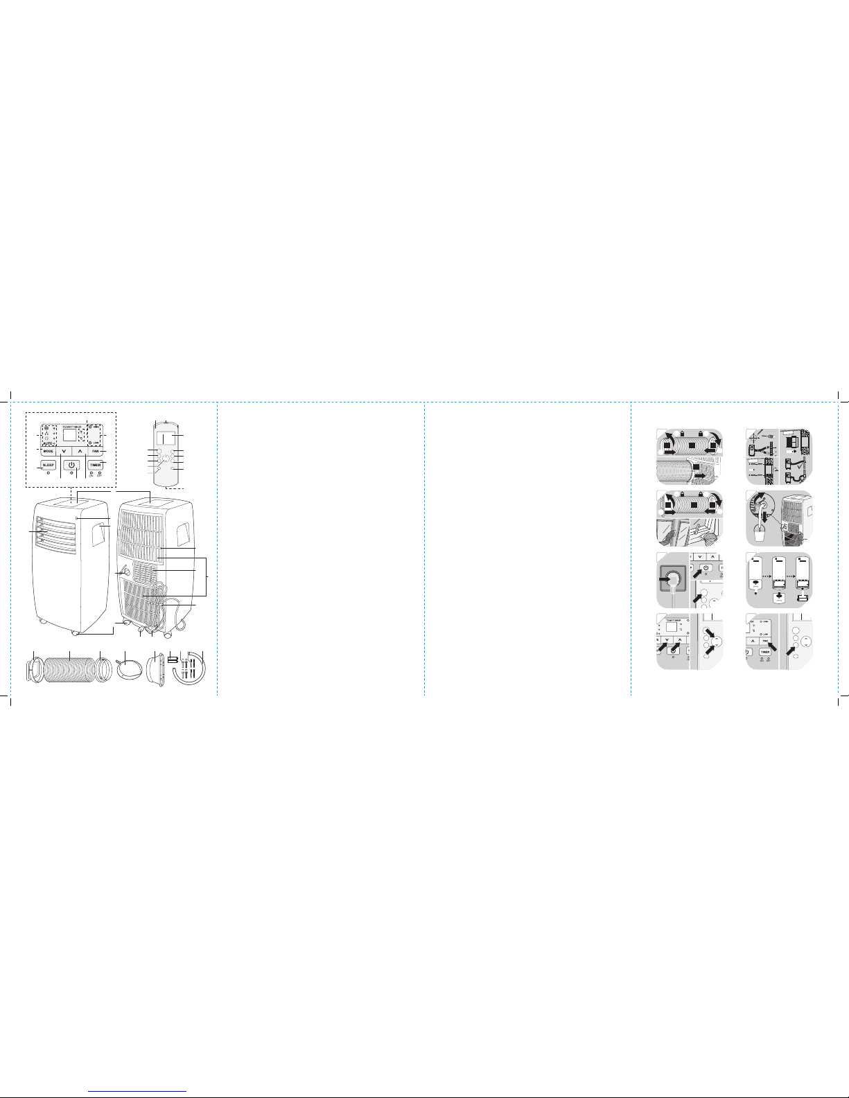
COMPONENTS
A. Control panel
1. Display
2. Unit indicator °F / °C
3. Fan speed indicators HIGH / LOW
4. Fan speed button FAN
5. Timer program button TIMER with indicators
6. Increase button
7. On/standby button with indicator
8. Decrease button
9. Sleep mode button SLEEP with indicator
10. Mode selection button MODE
11. Mode indicators AUTO / FAN / DRY / COOL
B. Louvre blade
C. Remote control receiver
D. Recessed handle
E. Upper drain outlet
F. Castor
G. Air lter
H. Air exhaust
I. Air inlet
J. Power cord tie
K. Power cord with plug
L. Lower drain outlet
M. Remote control
1. Remote control emitter
2. Display with function indicators
3. Pre-programmed button SHORT CUT
4. Timer button TIMER ON
5. Timer button TIMER OFF
6. Display/indicator ON/OFF button LED
7. Battery compartment with lid
8. Sleep mode button SLEEP
9. Temperature up/down
10. Fan speed button FAN
11. Mode selection button MODE
12. Power switch ON/OFF
N. Exhaust connector
O. Exhaust hose
P. Wall adapter
Q. Wall connector
R. Window outlet adapter
S. Battery (LR03/AAA, x 2)
T. Wall plug (x 4)
U. Screw (x 4)
V. Drainage hose
BEFORE FIRST TIME USE
• Remove the product and accessories carefully from the original packaging. It is recommended to keep
the original packaging for storage. If you wish to dispose of the original packaging, please observe
applicable legal provisions. Should you have any questions regarding proper disposal, contact your
local waste management center.
• Inspect the delivery contents for completeness and damages. Should the delivery contents be
incomplete or damaged, contact your sales outlet immediately.
• After unpacking, please refer to chapter Cleaning and care.
IM_OAC2221_161201_V04_HR.indb 21 1/12/16 4:31 PM
Page 22

22
EN
INSTALLATION
Placement
When choosing an installation place, consider following points:
• Observe all safety warnings!
• Ensure the minimum surrounding distance in every direction of 30 cm and 100 cm to other electrical
products.
• Keep a surrounding distance of minimum 50 cm around the outside of exhaust wall outlet and protect
it from entering objects and moisture.
• Make sure the wall behind the product is an exterior wall not a divider and the drill holes can be made
in a safe way, not obstructed by hidden objects in the wall.
• Ensure that a suitable power outlet is within reach at the desired location and remains accessible after
installation.
• Consider that during dehumidifying operation water is collected inside the product, which must be
continuously drained through a connected drainage hose into a suitable container or a nearby drain.
• Ensure there are no obstacles obstructing the airow.
Air exhaust
The exhaust hose and adaptor must be installed or removed in accordance with the usage mode:
• COOL, AUTO mode: install exhaust hose.
• FAN, DEHUMIDFY mode: remove exhaust hose.
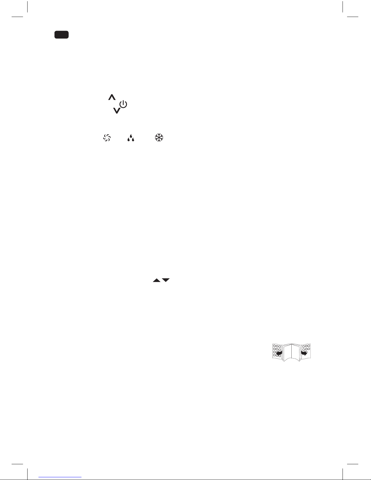
Wall (Parts: N, O, P, Q)
Fig.
1
Screw the wall adapter and exhaust adapter onto each side of the exhaust hose. Connect
the exhaust adapter to the air exhaust of the product.
Fig.
2
Use the wall connector as pattern to mark the hole spacing on the wall. Drill the holes
with a suitable power tool. Free the holes from dust and mount the wall connector using
supplied screws and plugs. Connect the wall adapter to the wall connector.
Note:
• The exhaust hose can be expanded and compressed, but for optimal performance, keep
the exhaust length to a minimum.
• Do not extend the exhaust hose.
• Avoid over-bending.
• Observe the decommissioning instructions in the respective section, if the product is
not to be used for a longer period of time.
Window (Parts: N, O, R)
Fig.
3
The exhaust hose can be attached to an open or tilted window alternatively. Screw the
window outlet adapter onto the open end of the exhaust hose.
Note: Material necessary for attachment and sealing is not provided but must be
purchased in special shops.
Drainage hose
Fig.
4
The drainage hose is used to drain water from the upper drain outlet.
1. Slide the drainage hose as far as possible onto the outlet.
2. Lead the other end of the drainage hose into a suitable container or a nearby drain.
Notes:
• Depending on the set modus the water is either drained directly or collected in an internal
tank. Drain the water respectively.
• Always cover the drain outlets when not in use.
• Observe the decommissioning instructions in the respective section, if the product is not
to be used for a longer period of time.
IM_OAC2221_161201_V04_HR.indb 22 1/12/16 4:31 PM
Page 23
23
EN
OPERATION
Fig.
5
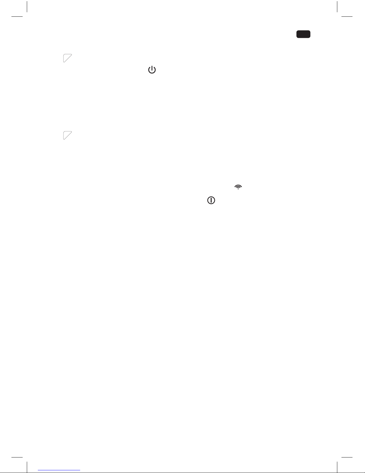
Switching on/o
The product can only be switched on or into standby. Unplug in order to switch o.
Press the on/standby button
or ON/OFF button to switch the product on or into standby.
Notes:
• After a power break or when the product is switched into standby and on again in a short
time, the refrigerating compressor will resume work after 3 minutes (delay start). This is to
prevent the refrigerating circuit from damages.
• If the product is knocked over, switch into standby and unplug immediately. Wait at least 2
hours before operating the product again, to avoid damages on the refrigerating circuit.
• Always switch the product into standby before unplugging.
REMOTE CONTROL
Fig.
6
Remove the battery compartment cover. Insert 2 batteries (type LR03/ AAA) while paying
attention to the correct polarity. Close the battery compartment. Using the control panel
and the remote control alternately might lead to a misalignment of the product and the
information displayed on the remote control.
• Press any button on the remote control and the product adopts the current setting from
the remote control.
Notes:
• The signals of the remote control will be transmitted with a short delay after a button
is pressed. This process is indicated by the appearing symbol
on the remote control
display.
• The operating product is indicated by the symbol on the remote control display.
IM_OAC2221_161201_V04_HR.indb 23 1/12/16 4:31 PM
Page 24
24
EN
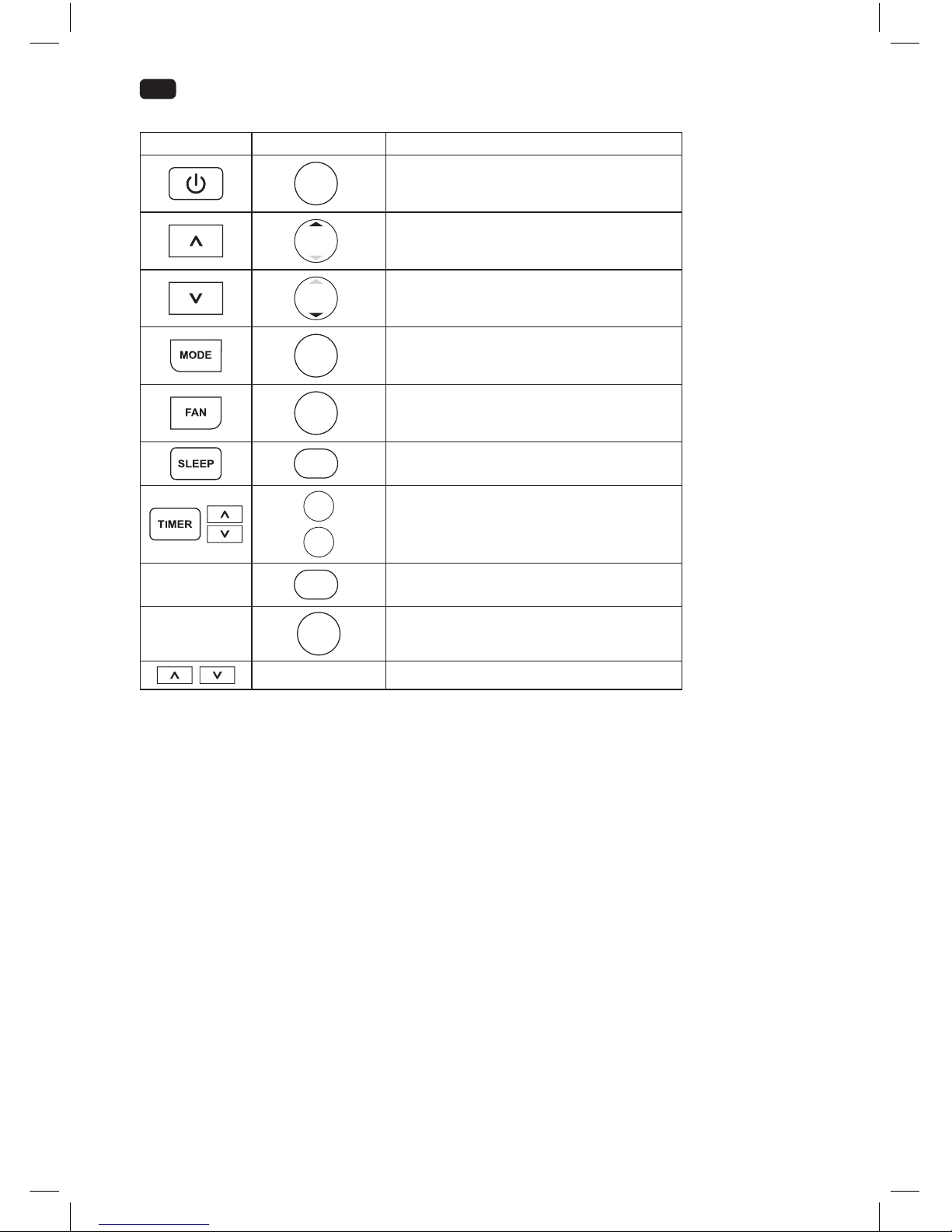
Functions
Control panel Remote control Function
ON/OFF
switch on or into standby
TEMP
increase value
TEMP
decrease value
MODE
toggle through modes
FAN
toggle through fan speeds
SLEEP
switch sleep mode on/o
TIMER
OFF
TIMER
ON
adjustment of timer on and standby time
-
LED
display and indicator lights on/o
-
SHORT
CUT
choose preset mode and temperature
- switch between °C and °F units
IM_OAC2221_161201_V04_HR.indb 24 1/12/16 4:31 PM
Page 25

25
EN
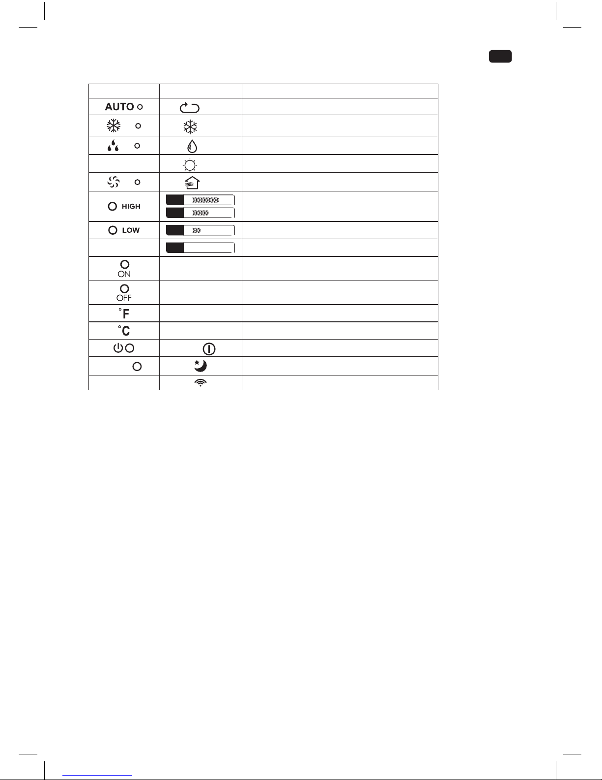
Indicators
Control panel Remote control Function
Auto
product in automatic mode
Cool
product in cooling mode
Dry
product in dehumidifying mode
-
Heat
function not provided
Fan
product in fan mode
FAN
FAN
fan speed set to high
FAN
fan speed set to low
-
FAN Auto
fan speed set to Auto
Timer On auto-on timer set
Timer O auto-o timer set
- temperature displayed in Fahrenheit (°F)
- temperature displayed in Celsius (°C)
— /
product in standby / on
SLEEP
sleep mode active
-
transmitting signal
Notes:
• Every press of a button on the control panel and every successfully transmitted signal from the remote
control is conrmed by an audible signal.
• All function of the product can be controlled via the control panel or the remote control, with
exception of the display illumination LED and SHORTCUT buttons, which are to be found exclusively
on the remote control.
IM_OAC2221_161201_V04_HR.indb 25 1/12/16 4:31 PM
Page 26

26
EN
Modes
Mode Application
automatic mode
• products selects the suitable mode to achieve the set
temperature
• fan speed is controlled automatically
• temperature can be adjusted
Auto
cooling mode
• cools down the room temperature
• the refrigerating compressor runs and stops in order to
maintain the set temperature
• fan speed and set temperature can be adjusted
Cool
dehumidifying mode
• dehumidies the room with the fan
• fan speed and set temperature cannot be adjusted
Dry
fan mode
• fan only
• fan speed can be adjusted
• temperature cannot be adjusted
Fan
timer mode
• switches the product on and / or into standby at a userdened time
TIME
sleep mode
• set temperature increases by 1 °C after 30 minutes and again
by 1 °C after another 30 minutes
• temperature will be kept for the next 7 hours and the
product returns then to the previously set temperature
• not available during fan or dehumidifying mode
SLEEP
Fig.
7
Setting the temperature
1. Press and hold both, the increase
and decrease buttons of the control panel at
once for more than 3 seconds to toggle between °C or °F.
2. Press the increase / or decrease / button separately to select a temperature
between 17 °C to 30 °C or 62 °F to 86 °F.
Fig.
8
Setting the fan speed
Press the fan speed button FAN to toggle between the speed settings. The respective
indicator on the control panel and the remote control show the current setting.
Note:
There is no indicator at the control panel for the auto speed setting.
Fig.
9
Louvre adjustment
The louvres of the air outlet can be adjusted manually in any mode to t required needs.
IM_OAC2221_161201_V04_HR.indb 26 1/12/16 4:31 PM
Page 27

27
EN
Fig.
10
Setting the timer
The timer switches the product on or into standby when a user-dened time has elapsed.
When switching on, the last mode and setting will be used. The set durations will be counted
down immediately after the input without correlation to the contrary time setting.
1. Press the timer program button TIMER at the product or the specic TIMER ON/OFF
button at the remote control to enter timer setting for either the auto-on or auto-standby
timer. The respective indicator for each setting will light up.
2. Press the
/ buttons or the specic TIMER ON/OFF button at the remote control as
often as necessary to set a time from 0.5 to 24 hours.
3. The setting will be saved after 5 seconds without input.
Examples:
• To have the product switched o after 1 hour and on again after another 1 ½ hours, set the
auto-o time to 1.0 h and the auto-on time to 2.5 h during operation.
• To have the product switched on after 8 hours and o after another 8 hours, set the autoon time to 8.0 h and the auto-o time to 16.0 h while in standby.
Notes:
• The adjusting increments are 0.5 hours up to 10 hours, then 1 hour up to 24 hours.
• The respective indicator will be lit, when a time is set.
• Switching the product on or into standby manually will cancel the timer setting.
• The timer settings will be lost once the respective actions were conducted and the time
needs to be set again.
• The timer setting will be lost in case an error occurs (see protection and error codes).
Preprogramming a function
By pushing the SHORTCUT button any function and temperature can be saved and recalled.
1. Choose your desired function e.g. using the MODE, TEMP
/ or / and FAN buttons, etc.
2. Press and hold SHORTCUT button until the display ashes one time to save the setting.
3. The preset setting can be recalled anytime and from any mode by simply pushing the SHORTCUT
button.
Fig.
11
WATER DRAINAGE
Water is only collected during automatic AUTO, cooling
and dehumidifying mode .
During dehumidifying mode water is drained immediately through the upper drain outlet
and the drainage hose must be continuously connected. The water is drained through the
hose into a suitable container or nearby drain.
WARNING – Danger of ooding! Do not leave the product unattended when draining to an
external container! Empty the container frequently to avoid spilling over and water damage.
During automatic AUTO and cooling mode water is collected in an internal tank, which
must be drained when full. In this case the product will emit an audible signal, while the
display on the control panel is showing the protection code P1. The cooling process will stop
until the water is drained and the product restarted, while the fan remains running.
1. Disconnect the product from the power supply.
2. Place the product with the lower drain outlet above a suitable container or a drain.
3. Remove the cover of the lower drain outlet.
4. Attach the cover of the outlet again, when all water is drained.
5. Connect the plug to a suitable socket.
6. The product is ready to be switched on.
IM_OAC2221_161201_V04_HR.indb 27 1/12/16 4:31 PM
Page 28

28
EN
CLEANING & CARE
Fig.
12
Switch the product into Standby and unplug in order to disconnect from the mains.
Note:
Clean the product every two weeks. Clean the outer surfaces of the product with a damp
cloth soaked in neutral detergent. Dry it with a lint-free cloth. Do not use chemical, alkaline,
abrasive or other aggressive detergents as they might be harmful to the surfaces.
Fig.
13
Remove the air lters. Clean the air lters in warm water (below 40 °C) and neutral detergent.
Fig.
14
Let them dry thoroughly before re-attaching.
• Do not open the housing of the product and do not insert any tools into the air vents.
• This product does not contain any parts that can be repaired or serviced by the consumer.
Contact a qualied specialist to have it checked and repaired as necessary.
DECOMMISSIONING
1. Drain all water from the product and dry it using the fan mode
for half a day in a dry, warm room
to prevent mould.
2. Switch the product into standby.
3. Unplug and x the power cord with the cable tie on the back of the product.
4. Remove the exhaust hose assembly from the product.
5. Cover all drain outlets.
6. Remove the batteries from the remote control.
7. Close the cover of the wall adaptor.
Fig.
15
TRANSPORTATION
• The product is heavy. Therefore move the product whenever possible by pushing or
pulling it, rolling on the castors.
• When lifting is unavoidable, use the recessed handles and lift with two people.
• Do not move the product during operation.
• Wait at least 2 hours after moving before operating the product to avoid damages on the
refrigerating circuit.
IM_OAC2221_161201_V04_HR.indb 28 1/12/16 4:31 PM
Page 29

29
EN
TROUBLESHOOTING
If there are any problems during operation, please refer to the following table. If problems cannot be
solved as indicated under Solution, please contact your manufacturer.
Problem Possible cause Solution
product does not
start
not connected to power supply connect to power supply
power cord or plug is defective check by a specialist
other electrical defect to the product check by a specialist
error occurred see protection and error codes
remote control faulty see below
remote control not
working
batteries exhausted replace batteries
product out of range or signals
disrupted by obstacle
move the remote control closer and
clear obstructions
other electrical defect to the remote
control
check by a specialist
timer not working implausible, contradictory or wrong
time set
check timer setting
unsatisfactory
cooling
nearby heat source hinders cooling
process
relocate product or remove heat
source
ventilation insucient ensure surrounding clearance
open window(s) or door(s) in the
room
close window(s) / door(s)
exhaust hose not properly connected
or blocked
connect properly or check for and
remove blockage
air lter(s) blocked clean air lter(s)
temperature set too high regulate the temperature controller
noise product is not levelled level the product
product contacts obstacle remove obstacle
Note:
Murmur of water is heard when the product is operating. It is a normal sound of the coolant circulating
in the system.
Protection and error codes
Code Cause Solution
P1 internal water tank full drain through lower outlet
E1 room temperature sensor error switch the product into standby, unplug and re-plug
E2 evaporator temperature sensor error switch the product into standby, unplug and re-plug
E4 control panel communication error switch the product into standby, unplug and re-plug
Note:
Contact the service centre if errors occur reputably.
IM_OAC2221_161201_V04_HR.indb 29 1/12/16 4:31 PM
Page 30

30
EN
TECHNICAL DATA
Power supply : 220 - 240 V~ 50 Hz
Power : 1300 W
Protection class : I
Cooling capacity : 2345 W (8000 BTU/h)
Suitable for rooms up to max 60 m³
Refrigerant : R410A / 0.270 kg
INFORMATION REQUIREMENTS
Product che
Local air conditioners
Y
IJ A
IE IA
E
EER
A
A
B
C
D
A
A
2,3
kW
2,6
EER
65
dB
0,9
KWh/60min*
626/2011
OAC 2221
IM_OAC2221_161201_V04_HR.indb 30 1/12/16 4:31 PM
Page 31

31
EN
OAC 2221
Description Symbol Value Unit
Sound power level
L
WA
65 dB
Global warming potential *
GWP
2088 kg CO2 eq.
Rated capacity for cooling
P
rated
for
cooling
2.3 kW
Rated capacity for heating
P
rated
for
heating
n/a kW
Rated power input for cooling
P
EER
0.9 kW
Rated power input for heating
P
COP
n/a kW
Rated Energy eciency ratio
EERd
2.6 -
Rated Coecient of performance
COPd
n/a -
Power consumption in thermostat-o mode
P
TO
0.8 W
Power consumption in standby mode
P
SB
0.4 W
Electricity consumption of single/double duct products
(indicate for cooling and heating separately)
DD: Q
DD
SD: Q
SD
0.9
DD: kWh/a
SD: kWh/h
Contact details for obtaining more information
Imtron GmbH
Wankelstraße 5, 85046 Ingolstadt, Germany
The rated cooling capacity was tested under following conditions:
Cooling operation Indoor 35 °C (DB) 24 °C (WB)
*
Note:
• This product contains uorinated greenhouse gas (hermetically sealed) which is dangerous for the
environment and contributes to global warming if released to the atmosphere.
• Refrigerant type: R410A
• Global warming potential (GWP): 2088
• Refrigerant leakage contributes to climate change. Refrigerant with lower global warming potential
(GWP) would contribute less to global warming than a refrigerant with higher GWP, if leaked to the
atmosphere.
• This product contains a refrigerant uid with a GWP equal to 2088. This means that if 1 kg of this
refrigerant uid would be leaked to the atmosphere, the impact on global warming would be 2088
times higher than 1 kg of CO2 , over a period of 100 years. Never try to interfere with the refrigerant
circuit yourself or disassemble the product yourself and always ask a professional.
• Energy consumption 0.9 kWh per 60 minutes, based on standard test results. Actual energy
consumption will depend on how the product is used and where it is located.
IM_OAC2221_161201_V04_HR.indb 31 1/12/16 4:31 PM
Page 32

32
EN
WIRING DIAGRAM
CN6
FAN
CN10
UP
GREEN(OR Y/G)
WHITE(OR BLUE)
BLACK(OR BROWN)
POWER
SW1
CN4
M
~
BROWN
BLUE
CN1
DISPLAY BOARD
P03P04
P01P02
CN3
Y/G
EL
S U
RY1
MOTOR
~
BLACK
M
Y/G
RED
CAP
COMPRESSOR
BLACK
RED
M
~
Y/G
BLUE
BLUE
CN6
FAN
UP
GREEN(OR Y/G)
WHITE(OR BLUE)
BLACK(OR BROWN)
POWER
SW1
CN4
M
~
BROWN
BLUE
CN1
DISPLAY BOARD
P03P04
P01P02
CN3
Y/G
EL
S U
RY1
MOTOR
~
BLACK
M
Y/G
RED
CAP
COMPRESSOR
BLACK
RED
M
~
Y/G
BLUE
BLUE
CN6
FAN
CN2
UP
GREEN(OR Y/G)
WHITE(OR BLUE)
BLACK(OR BROWN)
POWER
SW1
CN4
M
~
BROWN
BLUE
CN1
DISPLAY BOARD
P03P04
P01P02
CN3
Y/G
T1
EL
S U
RY1
MOTOR
~
BLACK
M
Y/G
RED
CAP
COMPRESSOR
BLACK
RED
M
~
Y/G
BLUE
BLUE
CN1
CN1
CN2
POWER BOARD
OPTIONAL
Th i s symbol indicates the elemen t is
op t ional,th e a ctu a l sh ape shall preva il
OPTIONAL
N
DISPOSAL
Do not dispose of this product as unsorted municipal waste. Return it to a designated collection
point for the recycling of WEEE. By doing so, you will help to conserve resources and protect the
environment. Contact your retailer or local authorities for more information.
Refrigerants must be evacuated and disposed of by a qualied specialist in accordance with
federal and local regulations before the product is scraped.
Please dispose of batteries in an environmentally friendly manner Do not put batteries into the
household waste. Please use the return and collection systems in your community or contact
the dealer where you purchased the product.
IM_OAC2221_161201_V04_HR.indb 32 1/12/16 4:31 PM
 Loading...