

Page 1
© 2015 OJ Electronics A/S
67345 02-15 (HKT)
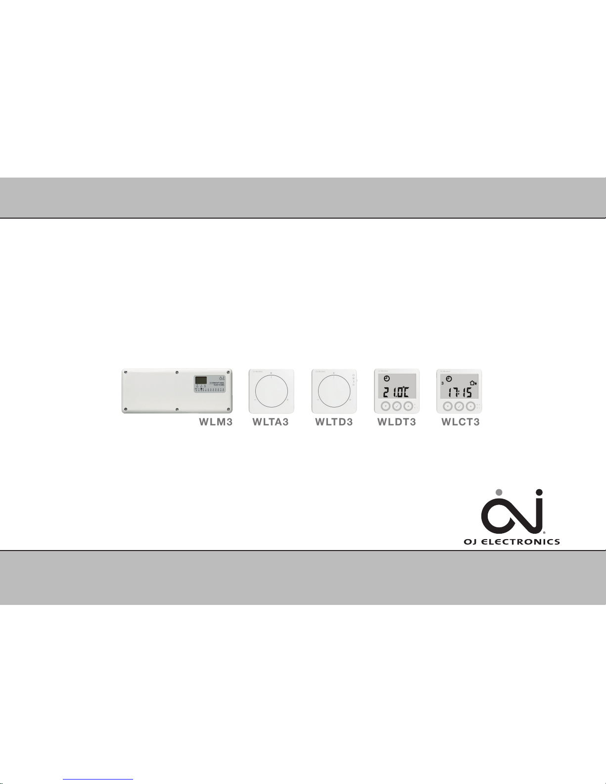
WLDT3
www.ojelectronics.com
Installation Manual
WLM3
WLCT3
WLTD3
WLTA3
Page 2
© 2015 OJ Electronics A/S
2
CONGRATULATIONS
Congratulations with you new control system for underfloor
heating and cooling.
The control system has been developed to provide a temperature
control system for room heating and cooling, integrating the switching
of primary heating and cooling sources with the control of water
temperature and mixing devices.
This ensures the best possible comfort conditions and also reduces
energy consumption.
Highlights of the system (depending on the units connected):
:: Heating and cooling control for true comfort
:: Humidity sensor to prevent condensation on floors
:: Energy saving comfort with adaptive function
:: Area control for easy operation
:: Flexible installation with wired and wireless connection
:: Network communication for large applications
:: Easy installation with plug and lead connections
:: Outdoor temperature compensation (optional)
:: Smart access with OJ FMSTM Gateway
for FS Master (optional)
Page 3

© 2015 OJ Electronics A/S
3
CONTENTS
INSTALLATION MANUAL
WLM3 Underfloor Heating Controller ............................................. 4
Description ......................................................................................... 7
Product programme ........................................................................... 7
Overall system configuration .............................................................. 8
Installation ......................................................................................... 9
Electrical installation .......................................................................... 9
Boiler demand (heat source) ............................................................. 9
Pump output .................................................................................... 10
Free relay function (X-OUTPUT) ....................................................... 10
Thermal actuators (thermoheads) .................................................... 12
External switch (timer) for night setback .......................................... 12
Room sensors - bus connection ..................................................... 13
Setting the channel........................................................................... 14
Room sensors - wireless setup ........................................................ 15
Supply water sensor and mixing valve ............................................. 16
Interconnection of WLM3 products .............................................. 17
Interconnections ............................................................................... 17
Special functions ............................................................................ 18
Creating a network ........................................................................... 18
Using cooling functions .................................................................... 19
Radiator mode .................................................................................. 20
2-step mode ..................................................................................... 20
Hot water mode ................................................................................ 21
Commissioning mode ..................................................................... 22
Replacing units ............................................................................... 23
Replacing a faulty room controller/sensor ....................................... 23
Guidelines and special features .................................................... 24
Power-up recommendations ............................................................ 24
Factory default settings .................................................................... 25
Error indication ................................................................................. 26
Special features .............................................................................. 28
Temperature and control .................................................................. 28
Replacing old masters ...................................................................... 29
Temperature control method ............................................................ 29
Emergency program ....................................................................... 29
Valve and pump exercising ............................................................ 30
Certifications................................................................................... 30
Disposal and recycling ................................................................... 30
Technical specifications ................................................................ 31
Waterline Add On Module - Type WLM3-xAO .............................. 33
Overall system configuration ............................................................ 33
Technical specifications ................................................................... 33
Waterline Outdoor Compensation Module - Type WLOC3 ......... 34
Introduction ...................................................................................... 34
Installation ........................................................................................ 34
Bus connection ................................................................................ 34
Technical specifications ................................................................... 34
Waterline Wireless Receiver - Type WLRC3 ................................ 35
Connection of receiver to master ..................................................... 35
Position ............................................................................................. 35
Master .............................................................................................. 35
Setting up the system ...................................................................... 35
Technical specifications ................................................................... 35
Waterline Room Controller - Type WLCT3 ................................... 36
Introduction ...................................................................................... 36
Installation ........................................................................................ 36
Getting started.................................................................................. 36
Everyday use of the room controller ................................................ 39
Programming 4-event times and temperatures ................................ 40
Advanced settings and read-outs .................................................... 41
Reset to factory settings - room controllers ..................................... 46
Radiator Mode .................................................................................. 47
2-step mode ..................................................................................... 47
Hot water mode ................................................................................ 47
Batteries ........................................................................................... 47
Technical specifications ................................................................... 47
Waterline Room Sensor with Display - Type WLDT3 .................. 48
Introduction ...................................................................................... 48
Installation ........................................................................................ 48
Getting started.................................................................................. 48
Everyday use .................................................................................... 49
Advanced settings and read-outs .................................................... 50
Batteries ........................................................................................... 50
Waterline Room Sensors - Type WLTx3 ...................................... 51
Introduction ...................................................................................... 51
Installation ........................................................................................ 52
Setting room temperature ................................................................ 53
Setting room sensor operating mode ............................................... 53
Batteries (wireless)............................................................................ 54
Technical specifications ................................................................... 54
Floor Limit Sensor - WLCT3, WLDT3 and WLTD3 ........................ 54
Page 4
© 2015 OJ Electronics A/S
4
* ON = Actuator output no. 1 is used as an ON/OFF
signal for a dehumidifier
WLM3 Underfloor Heating Controller
L
N
L
N
C1
C2
B1
B2
BR1025A09a
© 2015 OJ Electronic A/S
WLOC3
COOLING
SWITCH
-GB
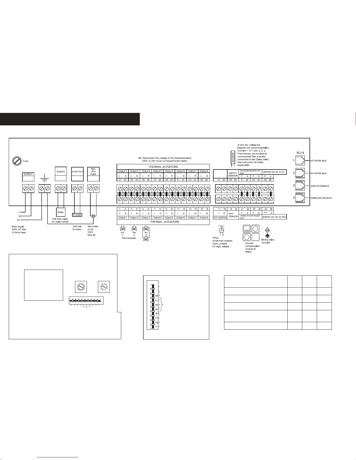
Wiring diagram WLM3-FS
Continuously
PE only
BR1025A09a
BR1025A11a
© 2015 OJ Electronic A/S
9
10
1
2
345
6
7
8
-GB
Top PCB
ON
OFF
Common UHF-PUMP
Commission mode
X-RELAY
Learn mode
Boiler test
Install mode
WLM2 Compatible
ON / OFF Control
String
number
(1-F)
Unit
number
(1-9)
BR1025A11a
BR1025A10a
© 2015 OJ Electronic A/S
9
10
-GB
ON
OFF
Common UHF-PUMP
Commission mode
X-RELAY
Learn mode
Boiler test
Install mode
WLM2 Compatible
ON / OFF Control
BR1025A10a
To control X-OUTPUT (X-relay)
for:
DIP-5 DIP-6 DIP-7
Boiler pump OFF OFF OFF
High-limit zone valve ON OFF OFF
Cooling device/module OFF ON *
Cooling device/module,
alternative
ON ON *
Differential thermostat OFF OFF ON
Page 5

© 2015 OJ Electronics A/S
L
N
L
N
C1
C2
B1
B2
BR1025A07a
© 2015 OJ Electronic A/S
WLOC3
COOLING
SWITCH
-GB
Wiring diagram WLM3-BA
Continuously
PE only
BR1025A07a
5
WLM3 underfloor heating controller
* ON = Actuator output no. 1 is used as an ON/OFF
signal for a dehumidifier
BR1025A11a
© 2015 OJ Electronic A/S
9
10
1
2
345
6
7
8
-GB
Top PCB
ON
OFF
Common UHF-PUMP
Commission mode
X-RELAY
Learn mode
Boiler test
Install mode
WLM2 Compatible
ON / OFF Control
String
number
(1-F)
Unit
number
(1-9)
BR1025A11a
BR1025A10a
© 2015 OJ Electronic A/S
9
10
-GB
ON
OFF
Common UHF-PUMP
Commission mode
X-RELAY
Learn mode
Boiler test
Install mode
WLM2 Compatible
ON / OFF Control
BR1025A10a
To control X-OUTPUT
(X-relay) for:
DIP-5 DIP-6 DIP-7
Boiler pump OFF OFF OFF
High-limit zone valve ON OFF OFF
Cooling device/module OFF ON *
Cooling device/module,
alternative
ON ON *
Differential thermostat OFF OFF ON
Page 6
© 2015 OJ Electronics A/S
L
N
L
N
BR1025A08a
© 2015 OJ Electronic A/S
WLOC3
-GB
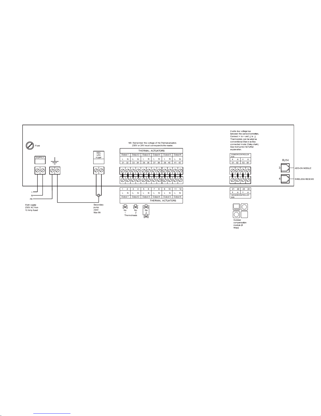
Wiring diagram WLM3-AO
Continuously
PE only
BR1025A08a
6
WLM3 underfloor heating controller
Page 7

© 2015 OJ Electronics A/S
7
The WLM3 underfloor heating controller is suitable for connecting multiple room controllers/sensors and
electric actuators (thermoheads) for an underfloor or radiator-based heating system.
Only OJ room controllers/sensors type WLxx3 that are prepared for 2 wire or wireless communication
can be used. For information on previous generations, see “Special Features - Replacing old masters”.
Description
Product programme
Product Thermoheads Type
Master for 8 zones 230V AC WLM3-1BA (basic system)
Master for 8 zones with display 230V AC WLM3-1FS (full system)
Master for 8 zones 24V AC WLM3-3BA (basic system)
Master for 8 zones with display 24V AC WLM3-3FS (full system)
Add-on module for 6 zones 230V AC WLM3-1AO
Add-on module for 6 zones 24V AC WLM3-3AO
WLM3 underfloor heating controller
Page 8
© 2015 OJ Electronics A/S
BR1025A02a
© 2015 OJ Electronic A/S
3
4567
8
12
OJ Waterline Master
WLM3 BA
TM
BR1025A02a
BR1025A01a
© 2015 OJ Electronic A/S
OJ Waterline Add-On
9 10 11 12 13 14
WLM3 AO
TM
BR1025A01a
BR1025A03a
© 2015 OJ Electronic A/S
1 23
4 5867
OJ Waterline Master
WLM3 FS BMS
TM
BR1025A03a
8
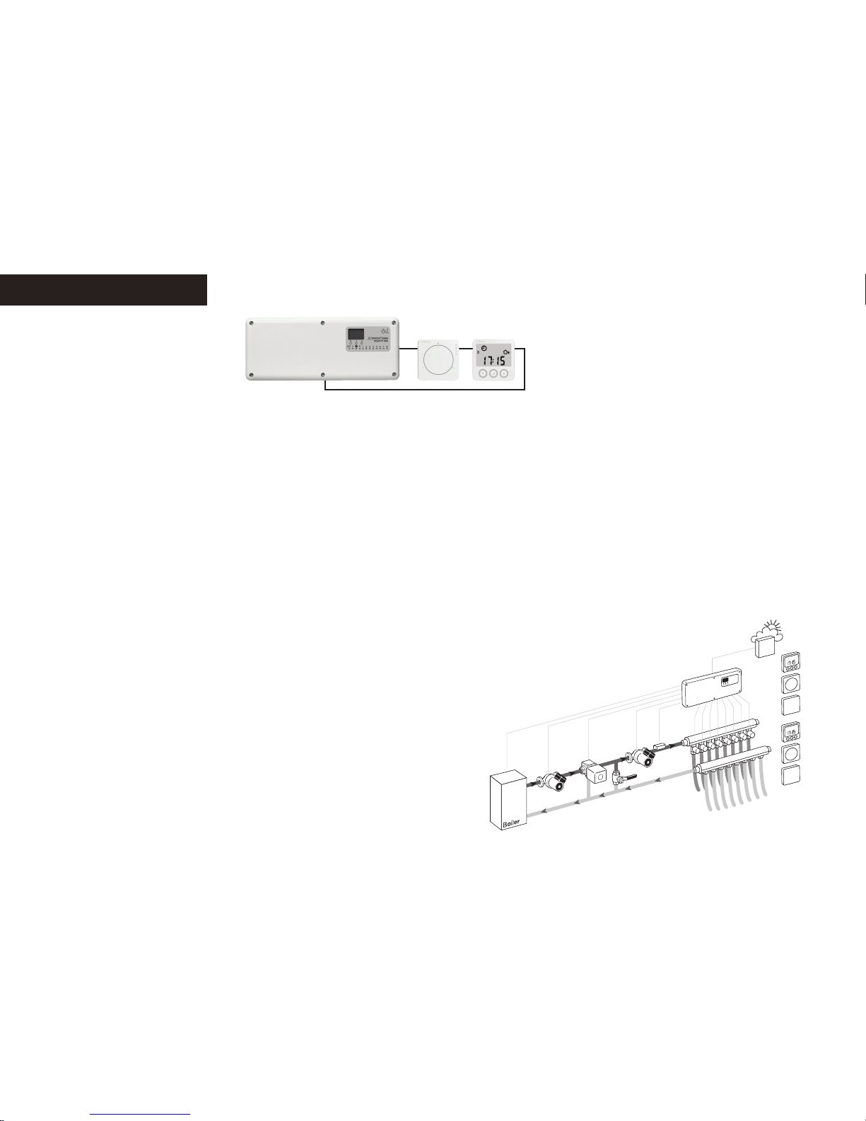
Each master module is capable of controlling 8 heating zones, each of which may use one or more
loops of piping, with one or more thermal actuators.
These zones are referred to later in this manual as channels 1 to 8. If more than eight zones are to be
controlled, it is necessary to install an add-on (AO) module, which provides another six outputs. The
AO module then controls channels 9 to 14.
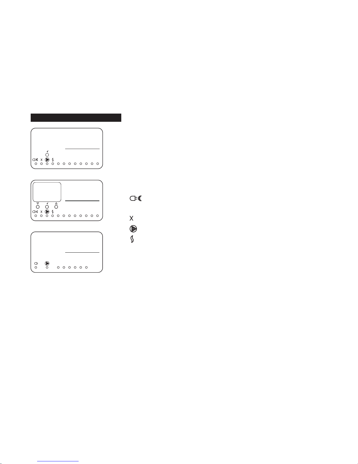
Overall system configuration
Green: Power supply connected
Red: Night setback active
Red flashing: Error
X-OUTPUT function active (see “Free relay function (X-OUTPUT)”).
Secondary UFH pump running
Boiler enabling signal active
1..8 Zones 1 to 8, indicating channel is active
Type WLM3-xBA
Type WLM3-xFS
Type WLM3-xAO
WLM3 underfloor heating controller
Page 9
© 2015 OJ Electronics A/S
9
Attach the WLM3 master to a suitable wall. It will generally be convenient if the unit is situated within 0.8
m of the manifold, as most thermal actuators are supplied with 1 m cable. Cables can be run across the
surface to the terminals using either the cable releases in the cover or by pressing out the cable entries
in the lower part of the cover.
PLEASE ENSURE THAT ALL WIRING IS CARRIED OUT IN ACCORDANCE WITH LOCAL
ELECTRICAL REGULATIONS.
When wiring is completed, fit the cover on the master using the screws provided.
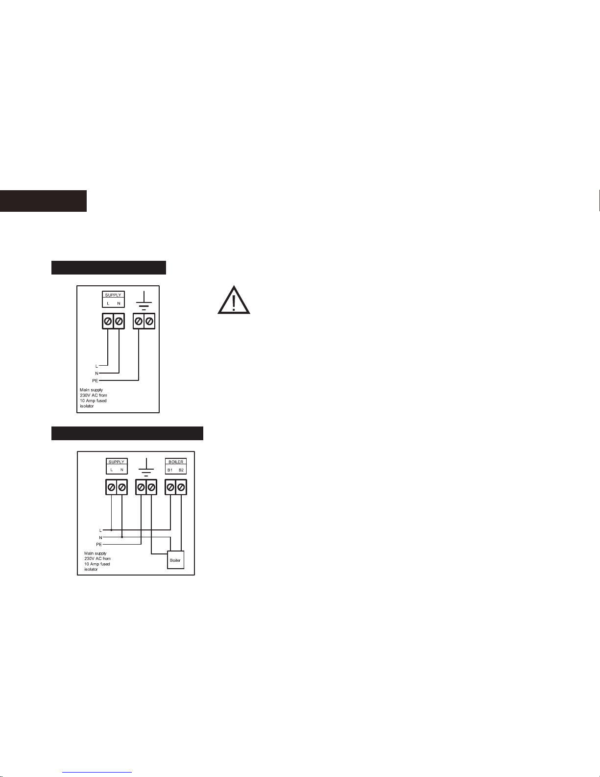
Mains supply
WLM3 requires a 230V AC mains supply connected to the terminals marked L, N, & PE
(Continuously PE only)
Electrical installation
Boiler demand (heat source)
The master has a volt-free relay output that can be used to control a boiler/heat pump or to open
a motorised valve.
A) To control a heat source that requires switching of the live supply, take a link from L (230V) to
the terminal marked BOILER - B1. Connect the heat source L to the terminal marked BOILER –
B2. Connect the heat source N terminal to the N terminal on the master, and the heat source PE
to the master terminal PE (see fig. 4A).
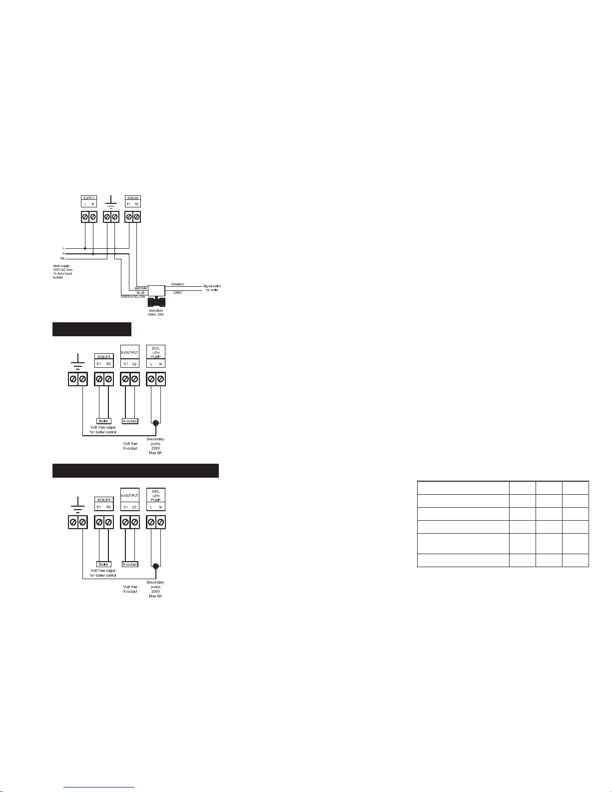
B) To control a heat source that has a pair of dedicated terminals for remote switching (e.g. by a
room sensor), connect these terminals to the terminals marked B1 and B2 on the master. B1 and
B2 are “volt free” terminals and can therefore be used for either a 230V AC or a 24V AC circuit
from the heat source.
BR965A13a
Fig. 3
Installation
Fig. 4a
BR965A14a
Page 10
© 2015 OJ Electronics A/S
10
C) To control a motorised valve
Many motorised 2-port spring return valves have wires coloured BROWN and BLUE for power
connections. In this case, BROWN must be connected to terminal B2 under the heading
BOILER and BLUE must be connected to terminal N on the master. Then link the L (230V)
terminal to the terminal marked BOILER - B1. The boiler relay will be energised after a delay of
10 seconds after the start of the main pump.
Basic versions without display. Type WLM3-xBA.
The boiler relay will stop if no heat is demanded by the room sensors.
Versions with display. Type WLM3-xFS.
These units have supply water temperature control. The boiler relay will switch ON once the
control valve has opened 20% and will remain ON for as long as a heat demand exists.
The master has an output for the underfloor circulating pump (secondary pump). The output will be
energised after a 180-second delay whenever any room sensor connected to the system calls for
heat. The delay allows time for the thermal actuator to start opening.
The 230V AC pump can be connected directly to terminals L and N under the heading SEC. UHF
PUMP . Connect the pump PE (earth) terminal to the PE (earth) terminal on the master. Maximum
pump load must not exceed 4 amps, 230V at start up. There is an overrun period of 1 minute after
heat is no longer demanded by the room sensor.
Delay times: Secondary UHF pump 180 sec.
X-OUTPUT (configured as main pump) 190 sec.
Pump output
Free relay function (X-OUTPUT)
All WLM3 masters have a relay which can be
utilized for a number of dierent purposes.
The relay is a volt-free output and is positioned
on the PCB as shown in the drawing.
The function of the relay is determined by the
DIP-switch settings.
The functions that the relay can control, and
the corresponding DIP-switch settings, are as
follows:
Installation
Fig. 4b
BR965A33a
Fig. 5
BR965A15b
Fig. 6a
BR965A15b
To control X-OUTPUT for: DIP-5 DIP-6 DIP-7
Boiler pump OFF OFF OFF
High-limit zone valve ON OFF OFF
Cooling device/module OFF ON *
Cooling device/module,
alternative
ON ON *
Differential thermostat OFF OFF ON
* ON = Actuator output no. 1 is used as an ON/OFF signal
for a dehumidifier
Page 11

© 2015 OJ Electronics A/S
11
The X-OUTPUT relay is volt free as shown in fig 6a. If the relay is required to be used as an L & N switch, link the
mains L terminal to the C1 terminal, then connect the L terminal of the device to the C2 terminal and the N terminal
of the device to the mains N terminal.
Boiler pump
Where a primary boiler pump is to be switched on by the master, the relay output can be used for this purpose. The
relay will be activated 10 seconds after the UFH circulating pump has started.
High-limit zone valve
This function is used where additional protection is required to prevent boiler water from entering the underfloor
system when the system is OFF or when the supply water temperature exceeds 65°C.
An additional sensor (ETF-522), referred to as ‘Application Sensor’ in fig. 6d, is required and a zone valve must be
connected via the X-OUTPUT (see example in fig. 6c).
Cooling device/module
The relay output can be used to provide a volt-free signal to a heat pump or to a K-MOD switching module where a
chiller is utilized to provide cooling water. The relay is ON when there is a cooling demand. (For further information,
see “Using cooling functions”.)
Cooling device/module, alternative:
The relay output is always ON in cooling mode and OFF in heating mode. (For further information, see “Using
cooling functions”.)
Dierential thermostat
The relay output can be used to enable use an alternative energy source, e.g. solar energy. In this case, the supply
water sensor must be supplemented with an additional sensor (ETF-522), referred to as ‘Application Sensor’,
which is used to monitor the temperature in the water storage cylinder of the alternative energy source. If the
system detects (via the Application Sensor) that this temperature is more than 3°C higher than the supply water
temperature, it activates the X-relay to select the alternative energy source via a valve and/or pump.
Installation
BR1025A10a
© 2015 OJ Electronic A/S
9
10
-GB
ON
OFF
Common UHF-PUMP
Commission mode
X-RELAY
Learn mode
Boiler test
Install mode
WLM2 Compatible
ON / OFF Control
Fig. 6b
BR1025A10a
Fig. 6c
BR965A40a
BR1025A19a
© 2015 OJ Electronic A/S
WLM3-BA/FS
MASTER
-GB
BOILER
MANIFOLD
MANIFOLD
Supply water sensor
(if fitted)
Application Sensor
(High limit sensor)
High limit
zone valve
Bypass
Fig. 6d
BR1025A19a
Page 12
© 2015 OJ Electronics A/S
12
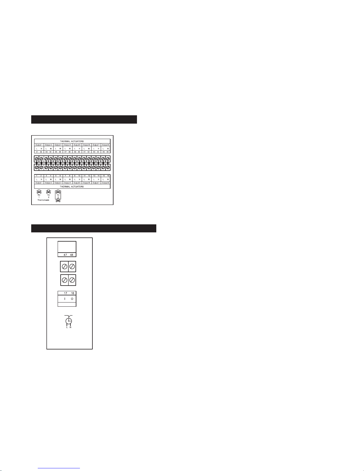
Thermal actuators are fitted to the underfloor manifolds and control the water supply through the various
loops. The voltage of the thermal actuators, 230V or 24V, must correspond that of the master.
WLM3-xBA masters are for 230V thermal actuators, while WLM3-xFSmasters/add-on modules are for 24V
thermal actuators. Up to 8 dierent zones can be controlled by the master. Connect the thermal actuator(s)
on the loop(s) for each zone to the corresponding terminals on the master. Thermal actuators for zone 1
must be connected to Output 1 terminals, thermal actuators for zone 2 must be connected to Output 2
terminals and so on.
Guideline
More than one thermal actuator can be connected to the terminals of a single output, provided that the
heads are to be controlled by the same room sensor/controller.
Connect the brown wire to the L terminal, and the blue wire to the N terminal. When installation is complete,
check that the room sensor in, for example, room (zone) 1 operates the thermal actuator(s) on the manifold
intended for that room. If the actuators appear to be in the wrong position on the manifold, it may be simpler
to interchange them on the manifold rather than reconnect them on the master.
BR1025A12a
BR1025A12a
© 2015 OJ Electronic A/S
COOLING
SWITCH
-GB
Timer
W/volt free contacts.
Open contacts
for night setback.
Ext. Switch
Fig. 8
From the factory, the master is supplied with a jumper in the switch/timer IO terminals. The current
operating setpoint of the master can be forced into night temperature by breaking this signal via an input
from an external switch or timer. The input must be a volt-free switch, and will need to open the circuit for
night temperature and close the circuit for day temperature. When the external switch or timer is used to
switch to night setback, this will override any time settings in the WLCT3 room controller, including any
room sensors that are part of a group allocated to that room controller.
External switch (timer) for night setback
Installation
Thermal actuators (thermoheads)
BR965A16a
Fig. 7
Page 13

© 2015 OJ Electronics A/S
13
Room sensors - bus connection
Only OJ units which are suitable for two-wire communication can be used.
Standard installation cable of minimum 2 x 0.25 mm² can be used. Units can be connected in conventional
star formation or in bus mode (daisy chain).
The master has 4 sets of terminals marked SENSOR/CONTROLLER BUS that can be used for connecting
the 2-wire signal cable from the unit.
There are 4 identical sets of terminals for convenient installation. Any unit can be connected to any pair
of terminals. The total length of the 2-wire system can be up to 300 m with a maximum length of 100 m
between any two units. For further information, see the table below.
Remember to connect + to + and – to – .
Table: Length of cable
Standard cable Max. cable length from master to room
controller/sensor with display
Max. cable length from master to room
controller/sensor without display
≥0.25 mm
2
Up to 100 m * Up to 300 m
≥0.50 mm
2
Up to 200 m * Up to 300 m
≥0.75 mm
2
Up to 300 m * Up to 300 m
*) Up to 300 m if operation without backlight is acceptable.
Installation
Fig. 9a
BR965A18a
SENSORS/CONTROLLERS CONNECTED IN STAR
Fig. 9b
SENSORS/CONTROLLERS CONNECTED IN BUS MODE
(DAISY CHAIN)
Fig. 9c
SENSORS/CONTROLLERS CONNECTED IN STAR SENSOR/CONTROLLERS CONNECTED IN BUS MODE
(DAISY CHAIN)
Page 14
© 2015 OJ Electronics A/S
14
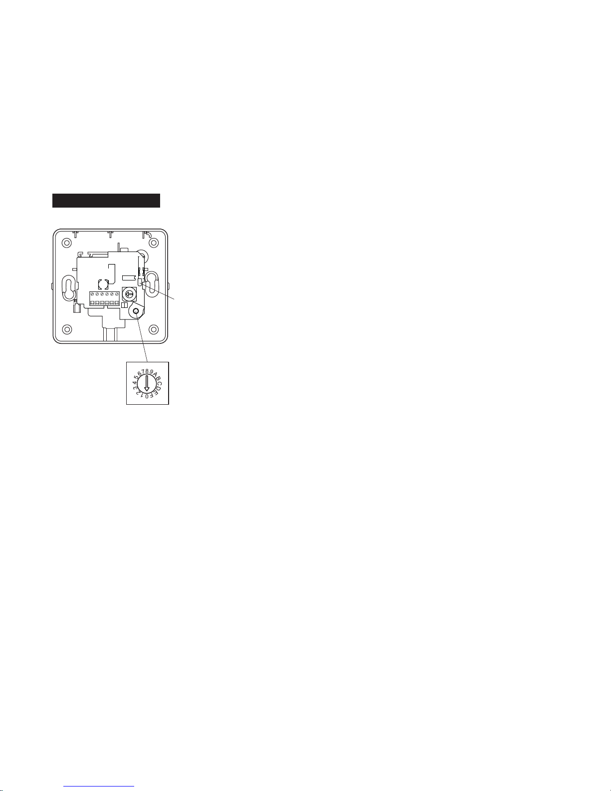
Setting the channel
Each room sensor can be set to operate a specific output which in turn controls a thermal actuator
on the manifold. A selector can be accessed under the front cover of the unit where the number of its
output (i.e. its channel number) can be set with a screwdriver (see fig. 10). Up to 14 channels can be
set on the selector, and there are two auxiliary channels (see later). A WLM3 master has 8 outputs. It
can be connected with an add-on slave module with an additional 6 outputs, creating a system with 14
individual zones.
Please note that channels 10 to 14 are marked as A through E on the selector,
A room sensor set for channel 1 will activate the thermal actuator connected to output 1 on the master.
The channel number can be set before power is connected to the system. The channel set on the room
sensor can be changed afterwards if needed.
If two room sensors are placed in the same room and set to the same channel, temperature will be
controlled by the average of the temperature recorded by both units.
Channel 0:
Each Room sensor is delivered with the switch in position 0. It must therefore be set to operate correct
channel output. Channel 0 can also be used for a room controller which is only used to control a group
(area) of room sensors without actually controlling the room in which it is installed (e.g. a controller in
the kitchen which is only used to control sensors located in other rooms). Setting the room controller
to channel 0 means that times and temperatures must be set on the WLCT3 for the group (area). The
WLCT3 will not, however, control a specific output itself.
Channels 1..14:
A room sensor set for Ch1 will activate the thermal actuator connected to output 1 on the master. If
several room sensors are set to the same channel number, heating will be controlled in the following
way:
- Actual room temperature will be calculated as an average.
- The room temperature setpoint will be calculated as an average.
- If floor sensors are connected to the room sensors:
The lowest value of any floor sensor is used as the minimum limit temperature.
The highest value of any floor sensor is used as the maximum limit temperature.
Channel 15 (position F on the switch): Party and holiday function.
Special function. “Special Features” for further instructions.
Testing the system: See “Guidelines and Special Features – Power-up recommendations”.
Installation
Fig. 10
BR1026A07a
© 2015 OJ Electronic A/S
Jumper
-GB
BR1026A07a
Page 15
© 2015 OJ Electronics A/S
BR1026A09a
© 2015 OJ Electronic A/S
Channal
selector
-GB
Jumper
Button learning
mode
Learning mode button
BR1026A09a
15
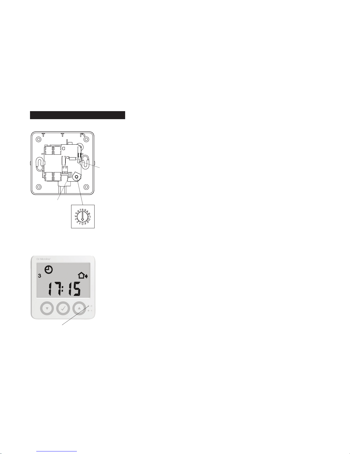
Room sensors - wireless setup
WLxx3-29 wireless room sensors/controllers must be paired with a WLM3 master for wireless
communication.
To achieve this:
1. On the master, switch on DIP-3 to activate learning mode.
2. Initialize all wireless room controllers/sensors:
- Initialize analogue room sensors (WLTA3, WLTD3 and WLTM3) by removing the plastic battery pull
tab or pressing the internal initialization button (learning mode button) until a beep is heard.
- Initialize digital room controllers/sensors (WLCT3 and WLDT3) by pressing the pinhole button
(learning mode button) beside the clock or I symbol until a beep is heard.
When communication with a room controller/sensor has been established, the corresponding channel
LED on the master will light up.
3. Switch o DIP-3 to deactivate learning mode.
Fig. 11a
Fig. 11b
Installation
Page 16
© 2015 OJ Electronics A/S
16
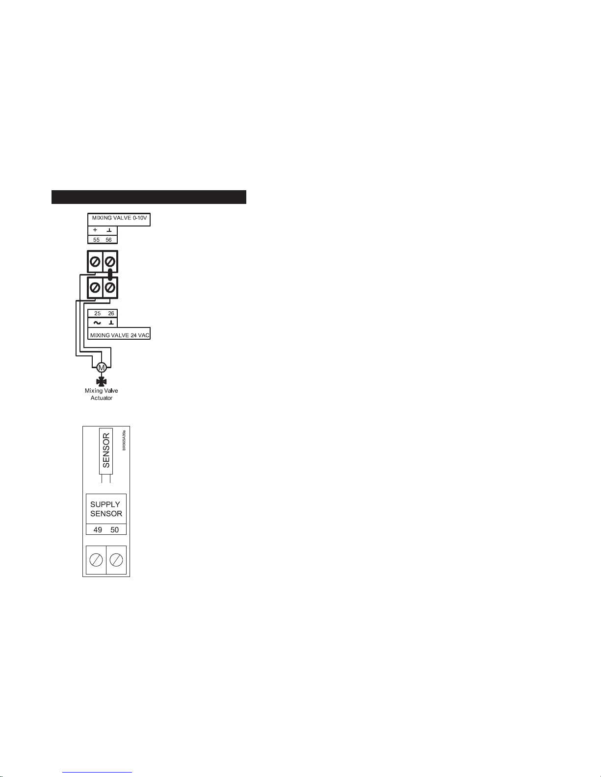
Supply water sensor
This feature, which limits supply water temperature, is available on full system masters, WLM3-xFS.
The supply water sensor should be connected directly to the master via the terminals marked Supply
Sensor. A temperature sensor of type ETF-522 must be used.
The sensor should be placed on the supply water pipe to the underfloor heating system. If a sensor is
installed in a system without a weather compensation module (WLOC3), the master will maintain the
design supply water temperature. The factory default setting can be changed via the display.
If a weather compensation module (WLOC3) is added to the system, the master will vary the supply
water temperature setting according to the outdoor temperature. A standard factory-programmed
compensation curve is used for this purpose. If needed, the curve can be changed, see separate USER
MANUAL, MASTER TYPE WLM3.
Mixing valve actuator control
A mixing valve actuator can be controlled by digital WLM3-xFS masters.
The actuator must be 24V AC powered (max. 6VA) and positioned via a 0-10V DC signal. It should be
configured so that it closes the valve if there is no heating demand (0V DC signal). If required, the control
signal can be reversed to 10-0V via the master's menu system.
Control action of the mixing valve actuator is P + I, and the parameters can be changed if required in the
master's menu system.
Please contact your supplier for further instructions.
Installation
Supply water sensor and mixing valve
Fig. 12b
BR965A39a
Fig. 12a
BR965A19b
Page 17
© 2015 OJ Electronics A/S
17
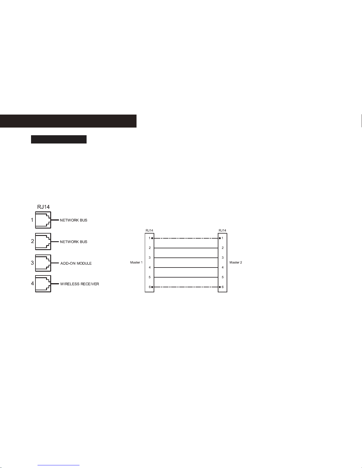
Interconnection of WLM3 products
Interconnections
* Although these connections are not
necessary, they are permitted
NOTE: The illustration shows the
four internal RJ14 connectors of
the WLM3 master.
The WLM3-xAO add-on module
has only connectors points 3 and 4.
BR965A46a
For easy installation, interconnections between master modules, master and add-on modules, and
master and wireless receivers are made with pre-wired plug-in connectors (RJ14). For connecting
WLM3 add-on modules to WLM3 masters, a plug-in connector is provided with the add-on module.
Similarly, a WLRC3 wireless receiver is connected to a WLM3 master using the plug-in connector
provided with the receiver.
For connecting a WLM3 master to another master in a network, a plug-in connector kit (WLM-NET) is
available. CAT5 cable should always be used.
If a connector kit is not used, it is possible to connect masters using standard RJ14 connectors. In
this case, ensure that terminal 1 is connected to terminal 1 at the other end, and so on.
The same type of connection can be used from a master to an AO module.
Page 18

© 2015 OJ Electronics A/S
18
In large buildings with more than 14 zones where multiple manifolds are used,
it is possible to use multiple masters to create a single network.
One master must be defined as the “network controlling master” by setting
both encoders to zero (see figs 13a and 13b).
Subsequent masters (up to nine) should be connected as a “string”, where
they will all use a common pump.
If more than one pump is used, a separate string should be created for each
pump (see fig. 13a).
On the first string of masters, all left-hand encoders must be set to 1, and the
right-hand encoders set in sequence from 1 to 9.
On the second string of masters, all left-hand encoders must be set to 2, and
the right-hand encoders again set in sequence from 1 to 9. This numbering
system can be continued for up to 15 strings.
All masters must be interconnected using special cable via RJ14 socket 1 or 2.
(For further information, see “Interconnection of WLM3 products”.)
All masters must be connected in a daisy chain, NOT in a star formation (see
fig. 13c).
An FS master can be used as the “network controlling master” to control
central mixing of the supply water and boiler activation.
The “network controlling master” can also switch between cooling and
heating for the whole network using the WLAC3 interface module connected
to the thermostat bus.
Time and temperatures for the whole network can be controlled by a single
WLCT3 connected to the “network controlling master” if the WLCT3 is set to
channel F.
Special functions
Creating a network
Fig. 13a
BR1025A14a
© 2015 OJ Electronic A/S
WLM3-BA/FS
2,1
WLM3-BA/FS
2,2
WLM3-BA/FS
2,3
WLM3-FS
0,0
WLM3-BA/FS
1,2
WLM3-BA/FS
1,1
WLM3-AO
WLM3-BA/FS
1,3
-GB
Circulation pump control of each string
String 2
String 1
Boiler
4-port
valve
Network communication
BR1025A14a
Fig. 13b
BR1025A11a
© 2015 OJ Electronic A/S
9
10
1
2
345
6
7
8
-GB
Top PCB
ON
OFF
Common UHF-PUMP
Commission mode
X-RELAY
Learn mode
Boiler test
Install mode
WLM2 Compatible
ON / OFF Control
String
number
(1-F)
Unit
number
(1-9)
BR1025A11a
Fig. 13c
BR1025A18a
© 2015 OJ Electronic A/S
WLM3-BA/FS Master 1
WLM3-BA/FS Master 2
Master Cable
BR1025A18a
Page 19

© 2015 OJ Electronics A/S
Type WLHX3
19
• Anetworkmustalwayscontaina“networkcontrollingmaster”.
• Onmasterssetforthesamestring(samesettingontheleftencoder),allpumps,boilerandvalve
outputs will act simultaneously, enabling the use of a common pump on each string.
• IfonlyoneUHFpumpisusedinanetwork,DIP-8onthenetworkcontrollingmastermustbesetto
“ON”, enabling the UHF pump output on this master to control a common pump for the whole system.
• Allmastersinanetworkfollowthesamesynchronizedtimingforactuators,pumps,boilersandmixing
valve output.
• Ifalowersupplywatertemperatureisneededononeofthestrings,therstmasteronthisstring
should be an FS master with a local mixing valve and supply water sensor attached.
• WithFSmasters,aspecialstatusmenuisavailableonthenetworkcontrollingmasterwhenanetwork
is detected. With this menu, it is possible to check the network. Please refer to the USER MANUAL for
further instructions.
NOTE: For instructions on testing a network, see “Power-up recommendations”.
Using cooling functions
In addition to controlling heating, all WLM3 masters have the ability to control the cooling system.
• Toenablethecoolingfunction,aremoteheating/coolingchangeovermodule,WLAC3,andoptional
humidity sensor, WLHX3, must be connected.
• Alternatively, the cooling switch input on the master can be used to switch between heating and cooling.
• For instructions on using the X-OUTPUT as a cooling signal to control a chiller, reversible heat pump or
diverting valve, see “Free relay function (X-OUTPUT)”.
•
With BA masters, where dew point control is required, it is also necessary to install a sensor (ETF-522) on
the return water pipe of the floor heating system. The sensor must be connected to terminals 49 and 50.
Using the WLAC3 module:
• TheWLAC3modulemustbeinstalledinaconvenientpositionfortheuserandconnectedtothesensor/
controller bus as shown in the drawing.
• Ifa BMS system in used for the heating/cooling decision, a volt-free BMS signal (EXT) can be connected
to the WLAC3 and the slider switch on the right side of the WLAC3 must be set to the heating position
(in this situation the BMS signal has priority and we recommend that the slider switch button be removed
to avoid unintentional override). Alternatively the volt-free BMS signal (EXT) can be connected directly to
terminals 47 and 48.
Humidity sensor WLHX3:
• WithaWLHX3humiditysensor,thesystemcanlimitcondensationonoorsurfacesduetohighhumidity.
• TheWLHX3 must be installed in a room that is representative of the general humidity level in the building
and connected to the sensor/controller bus. More than one WLHX3 can be used if necessary, e.g. on
separate floors of the building. Where more than one humidity sensor is used, the master will use the
reading from the sensor detecting the highest dew point for control purposes.
Special functions
BR1026A08a
© 2015 OJ Electronic A/S
WLAC 3
Sensor/
controller
bus
EXT.
-GB
BR1026A08a
BR1025A10a
© 2015 OJ Electronic A/S
9
10
-GB
ON
OFF
Common UHF-PUMP
Commission mode
X-RELAY
Learn mode
Boiler test
Install mode
WLM2 Compatible
ON / OFF Control
BR1025A10a
Page 20

© 2015 OJ Electronics A/S
20
• If a dehumidifier is used, it can be connected via a relay using output 1 on the master and setting DIP-7
to “ON”. (NOTE: This output gives either 24V AC or 230V AC depending on the type of WLM3 master.
Channel 1 cannot be used for a room controller in this situation.)
• Whencoolingisenabled,thecoolingsetpointwillbedeterminedbythemasterandwilloverridethe
settings of any room controller to ensure optimum energy eciency. (The cooling setpoint will be +3°C
above the master's day setpoint.)
Where a radiator circuit is used, it is possible to control room temperature with a
special WLCT3 mode called Radiator Mode, thus optimizing energy savings. See
“Waterline Room Controller - Type WLCT3”.
The controller measures the temperature in the room, and a zone valve is then
controlled via the WLM3 master, which in turn activates the boiler on demand.
• TheWLCT3shouldbeinstalledinaconvenientpositionfortheuserandwhere
the temperature is representative of the room or area.
• Connect the controller to the WLM3 master using the sensor/controller bus.
• ConnecttheradiatorzonevalvetoanoutputontheWLM3 master and set the
channel number on the room controller to the corresponding number.
• The special radiator controller is available in wired or wireless version.
NOTE: When the WLCT3 is in radiator mode and heat is demanded, it does not
start the circulating pump of the underfloor heating system. When the system is in
cooling mode, all radiator circuits will be o.
Special functions
Type WLCT3
Type WLCT3
Radiator mode
2-step mode
BR1025A22a
BR1025A22a
© 2015 OJ Electronic A/S
WLM3-BA/FS
MASTER
-GB
STEP 1
STEP 2
BOILER
Additional heat
source in the room
like a radiator
BR1025A20a
BR1025A20a
© 2015 OJ Electronic A/S
WLM3-BA/FS
MASTER
-GB
BOILER
Radiator
It is possible to control a secondary heat source in a room (e.g. a backup radiator)
using the special 2-step mode of the WLCT3 controller. See “Waterline Room
Controller - Type WLCT3”. In addition to the primary underfloor heating output, 2-step
mode is able to control a second output as a boost function. This output will only be
activated if the required temperature cannot be achieved by the underfloor heating
alone within a preset time period.
• TheWLCT3shouldbeinstalledinaconvenientpositionfortheuserandwherethe
temperature is representative of the room or area.
• ConnectthecontrollertotheWLM3 master using the sensor/controller bus.
• Set the channel number on controller to correspond with the output on the WLM3
master that is connected to the underfloor heating actuator.
Page 21

© 2015 OJ Electronics A/S
21
• The next numerical output on the WLM3 master MUST be used for the secondary/boost function.
• Whenthesystemisincoolingmode,2-stepcontrolwillbedisabled.
• The 2-step controller is available in wired or wireless version.
NOTE: To avoid overloading the WLM3 master, we recommend that the secondary output is used as a
signalling function for a remote relay. See “Technical Specifications”.
It is possible to control domestic hot water temperature with a special WLCT3 mode called Hot Water
Mode, thus optimizing energy savings.See “Waterline Room Controller - Type WLCT3”.
A sensor is connected to the controller and measures the temperature in the hot water storage cylinder.
A zone valve is then controlled via the WLM3 master, which in turn activates the boiler on demand.
• Thesensor(ETF)shouldbeinstalledonthehotwatertake-opipeimmediatelyabovethestorage
cylinder. Use a fixing strap to attach it tightly to the surface.
• TheWLCT3shouldbeinstalledinaconvenientpositionfortheuser.
• WiththeWLCT3inhotwatermode,connectittotheWLM3masterusingthesensor/controllerbus.
• Connectthehotwatersensortothesensorterminalsofthecontroller.
• ConnectthehotwaterzonevalvetoanoutputontheWLM3 master and set the channel number on
the hot water controller to the corresponding number.
The hot water controller is available in wired or wireless version.
NOTE: When the WLCT3 is in hot water mode and heat is demanded, it does not start the circulating
pump of the underfloor heating system.
Special functions
Hot Water Sensor
Type
WLCT3
BR1025A06a
© 2015 OJ Electronic A/S
21
2423
22
+
+
+
+
51
5453
52
+
+
-GB
Remote sensor
for hot water
cylinder
WLCT3
hot water
mode
(Channel selector
set to output 1)
Sensor/controller bus
Sensor/controller bus
BR1025A06a
BR1025A21a
© 2015 OJ Electronic A/S
WLM3-BA/FS
MASTER
-GB
BOILER
Hot
Water
Cylinder
BR1025A21a
Hot water mode
Page 22

© 2015 OJ Electronics A/S
1 2 3 4 5 6 6
23˚C
Max.
Supply temp.
22
Commissioning mode
Digital masters feature a special “commissioning mode”, which allows supply water temperature to be
controlled to assist the drying out of a newly laid concrete floor.
To start this function:
• SetDIP-4to“ON”.
• Thiswillmaintainthesupplywatertemperatureat23°Cforthreedaysandwillfullyopenallmanifold
actuators.
• Then,forafurtherfourdays,thewaterwillbemaintainedatthemaximumsupplywatertemperatureset
in the WLM3 master menu while the manifold actuators will remain fully open.
• WhentheWLM3 master is operating in commissioning mode, the output LEDs will flash consecutively
and the word “commissioning” will flash on the display.
• The commissioning function is paused if the power supply is interrupted.
• Torestartcommissioningfromthebeginning,switchDIP-4to“OFF”andthenbackto“ON”.
• Todeactivatethefunction,switchDIP-4to“OFF”.
• After7days,commissioningmodeisendedandnormaloperationisresumed(evenwithDIP-4still
“ON”).
NOTE: This function conforms to BS/EN-1264 Part 4.
NOTE: Commissioning mode can only be activated on a WLM3-xFS master, and only if a supply water
sensor is mounted. Otherwise, the function will be interrupted immediately.
Special functions
BR1025A10a
© 2015 OJ Electronic A/S
9
10
-GB
ON
OFF
Common UHF-PUMP
Commission mode
X-RELAY
Learn mode
Boiler test
Install mode
WLM2 Compatible
ON / OFF Control
BR1025A10a
Page 23

© 2015 OJ Electronics A/S
23
Replacing a faulty room controller/sensor
1. Identify the sensor/controller to be replaced from the flashing output LED.
2. Switch OFF power to the master.
3. Replace the sensor/controller.
4. Switch ON power to the master.
5. Set the master to learning mode by switching DIP-3 to ON.
6. If the sensor/controller is wireless, press the learning mode button on the sensor/controller.
See “Installation” under “Waterline Room Sensors - Type WLTx”.
If the sensor/controller is wired, proceed to step 7.
7. Check that the corresponding output LED has changed from flashing to permanently ON.
8. Reset DIP-3 to OFF.
Important: Set the channel selector on the new sensor/controller to the same channel as
the defective sensor/controller that is replaced
Replacing units
Page 24

© 2011 OJ Electronics A/S
BR1025A10a
© 2015 OJ Electronic A/S
9
10
-GB
ON
OFF
Common UHF-PUMP
Commission mode
X-RELAY
Learn mode
Boiler test
Install mode
WLM2 Compatible
ON / OFF Control
BR1025A10a
24
Power-up recommendations
For any other changes in the system, use the quick guide and start the install sequence from the beginning.
When all connections are complete, we highly recommend that the connections between the sensors and
thermoheads are tested using the procedure below:
System check:
Correct operation of the system can be checked using a special “Install Mode”.
This enables the installer to individually test and verify each output.
Testing the system:
1. Switch on DIP-3 to activate learning mode: - the power LED will flash quickly
2. Each red channel LED on the master should now be lit if a sensor/controller is present on that channel.
3. Switch o DIP-3 to deactivate learning mode again – the power LED will stop flashing.
4. Set the setpoint on all adjustable room sensors/controllers to minimum.
5. Switch on DIP-1 on the master to activate install mode. Install mode will remain active for 2 hours.
Pumps, boiler, mixing valve and actuators should now be OFF.
6. Set the knob on the adjustable room sensor/controller in room 1 to maximum.
The red channel 1 LED should light up and the actuator on output 1 should activate, opening after a 1-3
minute delay depending on the type of actuator.
Important: If the room sensor/controller is of wireless type, a delay of up to 5 minutes may occur before
the channel LED lights up. The boiler will not operate during test mode unless DIP-2 is activated, see step
9 below.
7. Check that the UHF pump is running and that the mixing valve (FS master only) opens.
8. Check step 2 for all rooms.
9. Boiler test function: Switch on DIP-2. This closes the boiler start relay contacts for 1 minute.
10. To end system testing:
- Switch o DIP-1 to deactivate install mode.
- Switch o DIP-2 to deactivate the boiler test.
- Set all temperature knobs to default positions.
Room sensors WLTA3, WLTD3 and WLTM3 to zero (centre position).
Room controllers WLCT3/WLDT3 to 21°C (recommended).
- Set all override switches on WLTM3 and WLTD3 room sensors to automatic position (clock symbol).
Testing a network:
If a network of masters has been set up, communication between them must be tested.
When the masters acting as network slaves are in install mode (DIP-1 is ON), their power LED will flash briefly
whenever communication is detected (approx. every 3 sec). The WLM3-xFS network master features a menu
option that allows the number of network slaves present on the system, and whether there are any errors, to be
checked. (Please refer to the User Guide for information on this menu option). The system is now operating auto
-
matically.
TOTAL X
Guidelines and special features
Page 25

© 2015 OJ Electronics A/S
25
Guidelines and special features
Factory default settings
Master Settings Factory
settings
Own
settings
BA/FS Day temperature 21.0°C
Night temperature 18.0°C
OFF temperature 5.0°C
Floor limit temp., high 27.0°C
Floor Limit temp., low 17.0°C
FS Max. water temperature 55.0°C
Weather compensation
Cold (winter)
Outdoor temperature -3.0°C
Water temperature 45.0°C
Weather compensation
Warm (summer)
Outdoor temperature 20.0°C
Water temperature 25.0°C
Master Settings Factory settings
BA/FS Cooling mode Day cooling
temperature
Day heating temperature +
3.0°C
Night cooling
temperature
Day cooling temperature +
3.0°C
Dew point safety zone Dew point + 3.0°C
Room temperature
control
PI-control P = 5.0°C
I = 90 min
Floor Limit
temperature
control
P-control P = 4.0°C
Adaptive PWM
control
Max. permissible room
temperature fluctuation
+/- 0.5°C
PWM time interval
limits
15-45 minutes
Max. number
of connected
sensors
Wired and wireless 24
Sensor timeouts Wired 300 sec. (5 min)
Wireless 10000 sec. (2 h 45 min)
FS Minimum supply water
temperature for cooling
16.0°C
Supply water
temperature
control
PI-control P = 20.0°C
I = 300 sec.
Additional information
Page 26

© 2015 OJ Electronics A/S
26
During normal operation the power LED will be ON when the master is energised. The red output LEDs (1 to 8 on the master and 9 to 14 on the add-on
module) indicate whether the output relay is ON/OFF.
An error/fault is indicated if the power LED or one of the red output LEDs flashes. The problem can be identified by the number of times a specific LED
flashes, as described in the following:
Error number will be indicated by the number of flashes, with a pause of less than a 1/2 second between flashes. Indication will be followed by a pause of
2 seconds, after which the sequence will be repeated. Error codes can also be seen in the service menu of WLM3-FS masters (submenu 2).
Flashing power LED (red and green)
Communication to the network has errors. On the network master, it indicates that communication to one or more of the masters acting as network slaves
has been lost. On a network slave, it indicates that communication to the network master has been lost.
Flashing power LED (red)
E1, 1 flash One or more room sensors, room controllers, WLHX3s or WLAC3s that are set to channel 0 or channel 15 are no longer sending data to
the network controlling master. The fault can only be corrected by replacing the unit. The master must then be hard reset (see next page).
(NOTE: If the room sensor is of wireless type, the error/fault message could be an indication that the power has failed and that the unit's
internal battery needs to be replaced.)
E2, 2 flashes One or more units have been set to a channel number which does not exist in the system. For example, the message will occur if the
units are set to channels 9-14 and the required add-on (AO) module is not found in the system. The error can be corrected by setting the
channel number of the unit to one that exists in the installed master/add-on module system.
E3, 3 flashes Application sensor defective. The fault can only be corrected by replacing the temperature sensor. If the sensor has been deliberately
removed to change system operation, the master must be hard reset (see next page).
E4, 4 flashes The outdoor compensation module (WLOC3) is defective. The fault can only be corrected by replacing the outdoor compensation
module.
If the module has been deliberately removed to change system operation, follow the HARD RESET instructions (see next page).
E5, 5 flashes The external supply water sensor (type ETF-1899A) is defective. The fault can only be corrected by replacing the temperature sensor. If
the sensor has been deliberately removed to change system operation, the master must be hard reset (see next page).
E6, 6 flashes Internal overheating. The master has its own internal overheating protection system. The problem can be remedied by improving
ventilation around the master module.
E7, 7 flashes Defective internal overheating sensor. The master will operate as normal, but will no longer be protected against internal overheating. The
fault can only be corrected by replacing the master.
E8, 8 flashes Communication to the AO module has been lost. The fault can be corrected by re-establishing connection to the AO module or by
replacing the AO module if it is defective. If the AO module has been deliberately removed, the master must be hard reset.
E9, 9 flashes Total number of input units exceeded. Please contact the manufacturer or your local service engineer.
E10, 10 flashes No connection to wireless receiver, type WLRC3.
Only one error/fault condition can be shown at a time. If more than one error occurs, they will be prioritised in the order described (E1, 2, 3…).
Error indication
Guidelines and special features
Page 27

© 2015 OJ Electronics A/S
27
Flashing output LED (red):
A flashing output LED indicates that the room sensor/controller on that channel has a fault/error. Error codes can also be seen in the service menu
(submenu 2a).
E1, 1 flash The master has lost communication to the room sensor. The fault can be corrected by re-establishing connection to the room sensor.
The fault condition will be automatically reset once correct communication is resumed. If the room sensor is defective and has to
be replaced, or if it has been removed deliberately, the master must be hard reset. (NOTE: If the room sensor is of wireless type, the
error/fault message could be an indication that the power has failed and that the unit's internal battery needs to be replaced.)
E2, 2 flashes The internal sensor in the room sensor/controller is defective. The fault can only be corrected by replacing the room sensor/controller.
Once the new room sensor/controller has been installed, the master must be hard reset.
E3, 3 flashes The floor sensor connected to the room sensor/controller is defective. Replace the faulty sensor. Reset is NOT required.
E5, 5 flashes Two or more room controllers are trying to control this output. Check the “AREA” setting of the room controllers.
E6, 6 flashes Channel engaged. Several functions selected for same channel. Possible causes of the fault:
- Channel 1 used for dehumidification, but the channel is already active (engaged). This is only possible for channel 1.)
- Channels 2..14 used for the cooling output of in dual heating/cooling mode, but the channel is already active (engaged).
- Channels 2..14 used as step 2 output in 2-step mode, but the channel is already active (engaged).
- Channels 1..14 used for humidification (humidity sensor), but the channel is already active (engaged).
RESET
Two dierent reset actions can be used.
HARD RESET (only valid in day temperature mode - sun symbol)
Press the OK (
√) button for 5 seconds to initiate a hard reset. Initiation will be indicated by all output LEDs (1-8) lighting up consecutively. This reset will
remove from the system any room sensor with a defective input sensor or any defective AO module. The fault message will be reset but the defective
items will no longer be part of the system. For information on adding or replacing a new unit, see “Replacing equipment - Replacing a faulty sensor/
controller”. To erase the identity of the defective component from the master's memory, a hard reset must be performed. Hard resets do not alter the
temperature settings already programmed into the master.
FACTORY RESET (only valid in day temperature mode - sun symbol)
Press the OK (
√) button for more than 15 seconds to initiate a total factory reset. Initiation is indicated by the flashing of output LEDs 1,3, 5 and 7
alternating with the flashing of output LEDs 2, 4, 6 and 8 (while the OK (
√) button is pressed).
A factory reset will return all programmed temperature settings to the factory defaults. It will also remove all room sensors/controllers from the master's
memory and reset the system to accept only those room sensors/controllers that are functioning correctly.
For information on reconnecting room sensors/controllers, see “Replacing equipment - Replacing a faulty sensor/controller”.
Guidelines and special features
Page 28

© 2015 OJ Electronics A/S
28
SETTING TEMPERATURE
With masters with display, temperature setpoints can be altered on the display.
Room sensors with manual adjustment are capable of increasing or decreasing the preset day and night
setpoints on the master by ±4°C for the heating zone they are controlling.
The WLCT3 room controller has its own day and night temperature settings that can be set separately. If
room sensors with manual adjustment are attached to its ”group”, these will operate according to the same
settings as the WLCT3. There will, however, still be the possibility of local ±4°C adjustment.
OVERRIDE FUNCTION
CHANNEL F OPERATION (Channel 15)
By fitting a WLTM3 sensor to a WLM3 system, and setting its hex encoder to Channel F, a single override
function can be used to override all the automatic time and temperature functions of the master, including
those areas independently controlled by a WLCT3 room controller. This can be especially useful for long
periods where override would be beneficial, including for example holidays and other periods of absence
where a frost protection temperature needs to be maintained.
By setting the WLTM3 in your system to Channel F, override could not be simpler. On the right-hand side of
the controller is a slide switch with four positions which determines system functionality:
AUTO – This allows the system to run automatically according to the times set on the WLM3 master and
any WLCT3s
DAY - This keeps the system running according to the ‘day’ temperature setpoint. Any WLCT3s, or sensors
controlled by them, will not be aected by this operating mode.
NIGHT - This keeps the system running according to the ‘Night’ temperature setpoint. Any WLCT3s, or
sensors controlled by them, will not be aected by this operating mode.
OFF – This eectively turns the system OFF, although a ‘Frost Protection’ temperature of 5°C will be
maintained in this operating mode.
If you would like these functions to be added to your existing system, please consult you installer or service
engineer.
EXTERNAL TIMER (see also “Installation - External switch”)
The external switch or timer function on the master allows the whole system to be forced to use the NIGHT
setpoint.
The external switch must have volt-free contacts that are OPEN for the NIGHT setpoint, and CLOSED for
the DAY setpoint. The factory-fitted link wire should be removed when an external switch/timer is used.
If a WLCT3 room controller is used in a part of the system, using the external switch to select the NIGHT
setpoint will override the room controller.
Special features
Temperature and control
Page 29

© 2015 OJ Electronics A/S
29
Backward compatibility must be considered if an old master is replaced with a new WLM3 master. If any
of the connected room sensors or room controllers are of the old type, DIP-9 (WLM2 Compatible) must be
switched to ON.
This sets the WLM3 master into low-power bus mode and ensures that the old units are able to
communicate with the new WLM3 master.
In this mode, it is permissible to mix WLxx3 and previous generations of room sensors/controllers and other
units connected to the bus.
NOTE: The backlight on WLCT3 and WLDT3 will be disabled in WLM2 Compatible mode.
Emergency program
Emergency program for room control
- If a room sensor/controller is defective, or communication to the unit is interrupted, an alarm will be
triggered. Depending on the system configuration, control will continue in one of the following ways:
- If there are several units on the same channel, including a room sensor which is still operative, control will
continue as before, although without any contribution from the defective unit.
- If no operative room sensor/controller is found, the system will run constantly at 20% ON.
- If an outdoor sensor is connected, the system will run at 40% at outdoor temperatures of 10°C or lower,
decreasing to 0% at 20°C or more.
The emergency program is only available for channels used for heating control. Channels used for cooling
control will always run at 100% OFF in connection with a defective room sensor. With heating and cooling
installations, the system will always run at 100% OFF during cooling periods in connection with a defective
room sensor.
Emergency program for supply water sensor
- If the supply water sensor is defective, the system will run constantly at 20% ON for the valve.
- If an outdoor sensor is connected, the system will run at 40% at outdoor temperatures of 10°C or lower,
decreasing to 0% at 20°C or more.
Replacing old masters
Temperature control method
As default, the system controls temperature on the basis of the advanced PI control method, which ensures
high accuracy and long lifetime of the system.
In some cases, however, it may be preferable to use the simpler ON/OFF control method.
This is possible by activating DIP-10 (ON/OFF Control).
NOTE: Using ON/OFF control will make temperature control a little less accurate but the system will react
faster to changes.
Page 30

Certifications
Disposal and recycling
© 2015 OJ Electronics A/S
30
Valve and pump exercising
If valves or pumps are not used for automatic ON/OFF sequences over a 72 hour period, the
components will be exercised. The actuators will be activated for 3 minutes. The pumps will be
started for 10 seconds during that period, and the mixing valve, if fitted, will be opened and closed.
CE marking
OJ Electronics A/S hereby declares that the product conforms with the following Directives of the
European Parliament and of the Council:
Master
CE - 1993/68/EEC
LVD - low voltage directive: 2006/95/EC
EMC - electromagnetic compatibility: 2004/108/EC
RoHS - restriction on the use of certain hazardous substances: 2011/65/EU
WEEE - waste electrical and electronic equipment: 2012/19/EU
For other components, see the relevant instructions.
Applied standard(s)
Master
EN 60730-1, EN 60730-2-9
Recycling of packaging
Protect the environment by disposing of the packaging in accordance with local regulations for waste
processing.
Disposal of the product
Equipment containing electrical components must not be disposed of together with domestic
waste.
It must be collected separately along with other electrical and electronic waste according to
local and currently valid legislation.
Page 31

Technical specifications
© 2015 OJ Electronics A/S
31
WLM3-xBA
Purpose of control .........................Electronic temperature control of hydronic floor heating
Voltage ............................................................ 230V AC ±10%, 50 Hz
Output for thermal actuators WLM3-1BA......................................... 230V AC
WLM3-3BA.......................................... 24V AC
Max. total load (pumps, boiler and thermal actuators).......................................10 A
Output ......................................................8 outputs for thermal actuators
Control panel ....................................................... 1 LED indicates power
8 LEDs indicate thermal actuators
3 LEDs indicate pumps and boiler
1 LED indicates setback temperature
Reset alarm and restore factory settings
Relay output ................................................Thermal actuators or zone valves
8 outputs, max. 2 A, direct
Boiler, max. 5 A, voltage free
Main pump, max. 5 A, voltage free
Sec. pump, max. 5 A, direct
Control input......................................................Setback temperature, etc.
Temperature settings (permanent settings)
Room temperature............................................................. +21°C
Setback temperature........................................................... +18°C
Frost protection ................................................................ +5°C
Max. floor temperature ......................................................... +27°C
Min. floor temperature.......................................................... +17°C
Max. supply water temperature................................................... +55°C
Wireless communication .......................Can be achieved by connecting a receiver (WLRC3)
Ambient operating temperature ....................................................+0/+40°C
Method of mounting...............................................For mounting direct on wall
Type of action..................................................................Type 1.B.
Control pollution degree................................................................ 2
Software class ....................................................................... A
Overvoltage category ..................................................................III
Rated impulse voltage ...............................................................4 kV
Ball pressure temperature .......................................................... 125°C
SELV limit realized ................................................................ 5V DC
Enclosure rating ................................................................... IP 21
Dimensions........................................................H/130, W/315, D/53 mm
Page 32

© 2015 OJ Electronics A/S
32
WLM3-xFS
Purpose of control .........................Electronic temperature control of hydronic floor heating
Voltage ............................................................ 230V AC ±10%, 50 Hz
Output for thermal actuators WLM3-1FS......................................... 230V AC
WLM3-3FS.......................................... 24V AC
Max. total load (pumps, boiler and thermal actuators).......................................10 A
BMS and smart access protocol ......................................Standard RTU Modbus ®
Output ...............................8 outputs for thermal actuators and weather compensation
Control panel ....................................................... 1 LED indicates power
8 LEDs indicate thermal actuators
3 LEDs indicate pumps and boiler
1 LED indicates setback temperature
Backlit display
Relay output ................................................Thermal actuators or zone valves
8 outputs, max. 2 A, direct
Boiler, max. 5 A, voltage free
Main pump, max 5 A, voltage free
Sec. pump, max. 5 A, direct
Control input......................................................Setback temperature, etc.
Temperature settings Factory settings Range
Room temperature +21°C +5/+40°C
Setback temperature +18°C +5/+40°C
Frost protection +5°C +3/+8°C
Max. floor temperature +27°C +20/+40°C
Min. floor temperature +17°C +10/+30°C
Max. supply water temperature +55°C +25/+85°C
Weather compensation Factory settings Range
Low outdoor temperature -3°C -20/+10°C
Supply water temperature +45°C +30/+60°C
High outdoor temperature +25°C +10/+30°C
Supply water temperature +30°C +10/+40°C
Wireless communication .......................Can be achieved by connecting a receiver (WLRC3)
Weather compensation .........Can be achieved by connecting an outdoor temperature compensation
module (WLOC3)
Ambient operating temperature ....................................................+0/+40°C
Method of mounting...............................................For mounting direct on wall
Type of action..................................................................Type 1.B.
Control pollution degree................................................................ 2
Software class ....................................................................... A
Overvoltage category ..................................................................III
Rated impulse voltage ...............................................................4 kV
Ball pressure temperature .......................................................... 125°C
SELV limit realized ................................................................ 5V DC
Enclosure rating ................................................................... IP 21
Dimensions........................................................H/130, W/315, D/53 mm
Page 33

© 2015 OJ Electronics A/S
BR1025A16a
© 2015 OJ Electronic A/S
WLM3-BA/FS Master
WLM3-AO Module
AO Module Cable
BR1025A16a
33
Waterline Add On Module - Type WLM3-xAO
Each master module is capable of controlling 8 heating zones, each of which may use one or
more loops of piping, with one or more thermal actuators. These zones are referred to as channels
1 to 8. If more than eight zones are to be controlled, it is necessary to install an add-on module
((WLM3-xAO), which provides another six outputs.
The AO module then controls channels 9 to 14 (9-E on the hex encoder).
Connection of master and add-on module
Connect the AO module using the special cable included in the box.
Connect a fused 230V AC mains supply.
The sensor bus can be connected to either the WLM3 master or add-on module, using either bus
(daisy chain) or star connections. Thermal actuators 1-8 are controlled by the WLM3 master while
9-14 are controlled by the add-on module.
Important: All LEDs will flash in case of incorrect or lacking connection.
Overall system configuration
Technical specifications
See the Waterline Add-On Module Instructions.
Page 34

© 2015 OJ Electronics A/S
BR965A09a
BR1025A13a
BR1025A13a
© 2015 OJ Electronic A/S
WLOC 3
Master
34
Introduction
WLM3-xFS masters are supplied pre-prepared for weather compensation, and simply by adding an
outdoor compensation module on the 2-wire bus and a temperature sensor on the supply water side,
your control system can be weather compensated. Preset values are factory programmed but can
easily be adjusted according to local needs via the display on the master. See the “Master with Display
- Type WLM3” user manual for instructions on changing of the default factory settings.
Installation
The unit should be mounted under the eaves of the roof or, alternatively, 2-3 metres above ground
level. Direct sunlight or other heat sources, e.g. ventilation vents, must be avoided. The unit should
be mounted vertically with the cable entry downwards.
Bus connection
Only OJ units which are suitable for two-wire communication can be used.
Standard installation cable of minimum 2 x 0.25 mm² can be used. Units can be connected in
conventional star formation or in bus mode (daisy chain).
The master has 4 sets of terminals marked SENSOR/CONTROLLER BUS that can be used for
connecting the 2-wire signal cable from the unit.
There are 4 identical sets of terminals for convenient installation. Any unit can be connected to any pair
of terminals. The total length of the 2-wire system can be up to 300 m with a maximum length of 100
m between any two units. For further information, see the table below.
Remember to connect + to + and – to – .
Waterline Outdoor Compensation Module - Type WLOC3
Technical specifications
See the Waterline Outdoor Compensation Module Instructions.
Page 35

© 2015 OJ Electronics A/S
BR1025A04a
© 2015 OJ Electronic A/S
WLM3 - Master
WLRC3
BR1025A04a
35
Do not place the receiver inside a metal box. In case of communication problems it may be necessary
to move the receiver to a new location or to add an additional receiver.
The receiver is connected to the master or add-on module using the cable provided.
Max. distance between the master/add-on module and the receiver is 30 m. Two receivers can be
connected to a master or a master/add-on system using the RJ sockets provided. Additional receivers
can be connected if necessary – please ask your distributor's technical department. The master/add-on
module and receiver must be connected using the RJ14 connection points supplied.
Connect the receiver to the master, and the system will reconfigure itself for wireless operation.
See Quick Guide
Waterline Wireless Receiver - Type WLRC3
Connection of receiver to master
Position
Master
Setting up the system
Technical specifications
See the Waterline Wireless Receiver Instructions
Connection label
B A - +
Blue Red Brown Yellow
Page 36

© 2015 OJ Electronics A/S
Installation
36
INSTRUCTIONS
Introduction
Getting started
Fig. 1
Waterline Room Controller - Type WLCT3
Room controller type WLCT3 is a 4-event programmable controller used to control areas with underfloor heating or special
features of a WLM3 installation. The standard WLCT3 can be used to programme up to 4 time and temperature events over
a 24 hour period, based on a 7 day schedule. Once a WLCT3 has been installed, the times and temperatures for the area(s)
it controls will no longer be the defaults set on the main WLM3 master.
In addition to the WLCT3's immediate area of control, set in the ‘AREA’ option of its internal menu, the WLCT3 can control
the time and temperature characteristics of other sensors (up to 14) connected to the WLM3 master. This maximises
comfort and eciency while saving energy and reducing costs.
When the WLCT3 is used to control other areas, the ±4°C adjustment possibility on the other sensors will now be relative to
the WLCT3 setting. Example: A WLCT3 is set to 22°C and has been given control over ‘Area 1’. The WLTA3 sensor installed
in ‘Area 1’ now has a control range of 18°C (22-4°C) to 24°C (22+4°C).
In addition to the standard WLCT3 room controller, you may have added one of the following to your system:
2-step mode: This mode controls a secondary heat source, operating in a specific area as a boost function in
conjunction with the underfloor heating.
Radiator mode: This mode is used to control the radiators in a central heating system.
Hot water mode: This mode is used to control the production of domestic hot water.
Your installer should have set up the WLCT3 controller to suit your needs during installation. If, however,
you wish to change any of the settings, please follow the instructions detailed in the following pages.
The WLCT3 can be reset by pressing the button marked ‘R’ (see fig 1), this will allow you to return to the factory settings at
any time. Details of the default factory settings are given after the WLCT3 programming section of this manual.
BR1026A05a
BR1026A05a
© 2015 OJ Electronic A/S
A
B
CD
F
E
R
For installation instructions, see “Installation” under “Waterline Room Sensors - Type WLTx3”.
A:
B:
C:
Display Adjustment down OK - Accept
D:
E:
F:
Adjustment up Reset to factory
settings
Pinhole button for
clock adjustment
Buttons
Page 37

© 2015 OJ Electronics A/S
37
Display
Activating the room controller (first-time startup)
Waterline Room Controller - Type WLCT3
J
G
H
K
I
1. The first time power is connected (or after a factory reset), the clock and weekday will flash and must
be set.
2. The channel to be controlled from this room controller must then be selected.
3. Finally the “Area” (other channels) controlled from this WLCT3 must be selected.
NOTE: If you need to adjust the time at a later date, insert a pin into the hole marked for setting the clock.
AREA SETUP - see next page.
Press the UP (△) or DOWN (▽) button to select the correct
hours and then press the OK (√) button.
Press the UP (△) or DOWN (▽) button to select the correct
minutes and the press the OK (√) button.
Then press the UP (△) or DOWN (▽) button to select the correct
day and press the OK (√) button to confirm.
1-7
G: H: I:
Automatic mode Manual mode Time and
temperature
J: K:
Day number 4-event symbol
Wake Out
Night Home
Buttons
Page 38

© 2015 OJ Electronics A/S
38
Waterline Room Controller - Type WLCT3
ArEA - (group of rooms)
The rooms/channels set as part of the WLCT3 area will follow the automatic temperature settings of this room controller (4-event timer, min. and
max. floor temperature limits).
Set a channel (room) to ON if it is to be part of this area.
Example: An area could be the living room, kitchen, and children’s rooms, all of which have a high temperature requirement during the
afternoon and early evening and a lower temperature requirement during the morning and night. Each room has an associated channel number
(Ch1, Ch2, etc.) determined by the number of the output on the master which controls the valve/actuator for that room.
Example: A system may have the kitchen room sensor operating master output #4 and the children’s room sensor operating master output #5.
If the WLCT3 room controller is situated in the living room and operates output #1, the WLCT3 must be programmed to control output channels
1, 4, & 5.
1. Press the UP (△) or DOWN (▽) button to select the channel/room.
2. Press the OK (√) button to view the ON/OFF settings.
3. Press the UP (△) or DOWN (▽) button to change the ON/OFF settings.
4. Press the OK (√) button to return to the channel/rooms select menu.
Set the channel/room (Ch) to ON if it is to follow the settings of this room
controller.
A total of 14 channels/rooms can be controlled.
NOTE: If the channel selector (hex encoder) is set to 1 .. 14, the selected
channel will always be ON (cannot be set to OFF).
Page 39

© 2015 OJ Electronics A/S
39
Everyday use of the room controller
4-Event Clock Mode
Sleep
Return
Leave
home
Wake up
Waterline Room Controller - Type WLCT3
The day has been split into 4 events describing a typical day. When the room controller is in 4-event mode,
it will automatically change the temperature to the required level at the programmed times. As standard,
the room controller uses 4 events on days 1 to 5 (Monday to Friday) 2 events on days 6 and 7 (Saturday
and Sunday). Each event allows you to increase or decrease the set temperature. For information on
programming, see “Programming 4-Event Clock Time and Temperature” and “Advanced Settings and Readouts”.
4-event clock mode
/ automatic mode:
In automatic mode, the clock symbol ( ) and one of the 4-event symbols ( ) will be shown along with the
time and setpoint. For information on programming, see “Programming 4-Event Clock Time and Temperature”.
Comfort mode:
Temporary override
To temporarily override any temperature in the 4-event schedule, press the UP (△) button once to show the temperature
in the display. Then press the UP (△) or DOWN (▽) button to increase or decrease the temperature. The display flashes
for 5 seconds, and then reverts to the time. Override will operate until the next programmed event, when the thermostat
will return to the scheduled 4-event program.
Cancelling comfort mode (temporary override)
To cancel temporary override, press the OK (√) button twice.
Manual mode:
Permanent override
During holidays, the scheduled 4-event program can be overridden. Press the OK (√) button and then the UP (△) or
DOWN (▽) button until the override temperature is set. The set temperature will remain on the display and the unit will
continue to operate to this temperature permanently.
Cancelling manual mode
To cancel permanent override, press the OK (√) button once, and the unit will resume automatic operation.
Page 40

© 2015 OJ Electronics A/S
40
Programming 4-event times and temperatures
Waterline Room Controller - Type WLCT3
For each event, start time and required temperature must be set.
Example: You want the heating to start at 07:00 in the morning
and the temperature to be 25°C. Press the OK (√) button for 3
seconds and the start time will be displayed. Change this to
07:00 with the UP (△) or DOWN (▽) button. Press the OK
(√)
button to confirm.
The temperature will now be displayed. Change this to 25°C
with the UP (△) or DOWN (▽) button. Press the OK
(√) button to
confirm. This procedure can now be repeated for the second,
third and fourth events.
These settings will be valid for days 1-5, as shown on the
display. To program days 6 and 7, repeat the above. Days 6 and
7 are usually Saturday and Sunday, and only have two events
(generally morning ON and evening OFF).
The temperature can be set within the range of +5 to +35°C. It
is also possible to switch heating OFF for an event by reducing
the setting to 5°C and then pressing the DOWN (▽) button once
more.
NOTE: When programming the “Sleep” time (event 4), ensure
that it is before midnight (00:00).
Press the OK (√) button for 3 seconds to start programming
Days 1-5
: Time and temperature
: Time and temperature
: Time and temperature
: Time and temperature
Days 6-7
: Time and temperature
: Time and temperature
Page 41

© 2015 OJ Electronics A/S
41
Advanced settings and read-outs
Waterline Room Controller - Type WLCT3
Press the UP (△) and DOWN (▽) buttons simultaneously for 3 seconds. INFO will be displayed.
INFO - Information
INFO allows you to view the room and floor temperatures actually measured.
The floor temperature is only shown if a floor sensor is installed.
Software Version
Room temperature
Outdoor temperature
If no sensor is installed,
“OFF” is displayed
Press the UP (△) or DOWN (▽) button to view the various read-outs.
No changes can be made here. Use the OK (√) button to exit.
App – Application
Select if the room controller is to be used in one of the special modes.
On entering this menu, the current setting will be displayed.
Radiator mode
Operates the channel as a radiator zone. Operates as an ON/OFF
regulator, activates the X-OUTPUT and boiler (but not the UFH pump).
Channels selected in the ArEA menu will also act as radiator channels.
3 sec.
Page 42

© 2015 OJ Electronics A/S
42
Waterline Room Controller - Type WLCT3
2-step mode
Operates an additional output as a boost output.
The selected channel output is the normal floor heating output.
The next channel output is the boost output, which is activated under the
conditions below.
tEmP sets the temperature hysteresis.
(The tolerance before the second output is allowed to activate).
The menu is only shown if 2-step mode is set to ON.
timE sets the time during which temperature is permitted to be too low
before the second output is activated (the output with the next number).
The menu is only shown if 2-step mode is set to ON.
Hot water mode
Operates the channel as a thermostat for a domestic hot water cylinder.
Operates as an ON/OFF regulator, activates the X-OUTPUT and boiler
(but not the UFH pump).
Press the OK (√) button to return to the APP menu.
Page 43

© 2015 OJ Electronics A/S
43
Waterline Room Controller - Type WLCT3
PRO - 4-event sequence
It is possible to change the factory-set sequence for Days 1-5 (4 events) and Days 6-7 (2 events).
Days 1 to 5 are usually Monday to Friday, while Days 6-7 are usually Saturday and Sunday.
An event is either a comfort temperature or a setback temperature. You can select from the following sequences, which are displayed in the
form of a code.
4 events for 5 days, 2 events for 2 days.
Indicated by code 4:52
Select the required sequence with the OK (√) button.
4 events for 6 days, 2 events for 1 day.
Indicated by code 4:61
Select the required sequence with the OK (√) button.
4 individual events for each day of the week. Indicated by Code 4:70
Select the required sequence with the OK (√) button.
2 individual events for each day of the week. Indicated by Code 2:70
Select the required sequence with the OK (√) button.
2 events for 5 days, 2 event for 2 days. Indicated by Code 2:52
Select the required sequence with the OK (√) button.
Escape without any changes
Hi Li - Floor sensor Max. and min. permissible floor surface temperatures
A floor limit sensor can be connected to the room controller.
Max. limitation is used for safety purposes to prevent excessive floor temperatures. Wooden flooring should, for example, not be allowed
to exceed 27°C. The value can be set from 5°C up to 55°C. The value can also be set to OFF by adjusting the temperature to 55°C and then
pressing the UP button once more.
Min. limitation is used where the temperature of the floor must never fall below the set minimum temperature. Examples include kitchens or
bathrooms with tiles. The value can be set from 5°C to 55°C. The value can also be set to OFF by adjusting the temperature to 5°C and then
pressing the DOWN button once more. Remember that the max. limit temperature must be set higher than the min. limit temperature.
The limit temperatures defined in the room controller will be valid for all room sensors with floor limit sensor (type WLTD3) included in the area
allocated to the WLCT3 controller.
Page 44

© 2015 OJ Electronics A/S
44
Waterline Room Controller - Type WLCT3
The maximum permissible floor temperature setting is shown. Use the
UP (△) or DOWN (▽) button to increase or reduce the setting, then press
the OK (√) button to accept.
The display now shows LoLi. Press the OK (√) button to continue.
The minimum permissible floor temperature setting is shown. Use the UP
(△) or DOWN (▽) button to increase or reduce the setting, then press the
OK (√) button to accept.
SCAL - Time format and temperature scale selection
You can select either °C or °F and 12 or 24 hour clock as follows:
Press the UP (△) or DOWN (▽) button to change the settings. Confirm
the required scale with the OK (√ ) button.
ArEA - (group of rooms)
The rooms/channels set as part of the WLCT3 area will follow the automatic temperature settings of this room controller (4-event timer, min.
and max. floor temperature limits).
Set a channel (room) to ON if it is to be part of this area.
Example: An area could be the living room, kitchen, and children’s rooms, all of which have a high temperature requirement during the
afternoon and early evening and a lower temperature requirement during the morning and night. Each room has an associated channel
number (Ch1, Ch2, etc.) determined by the number of the output on the master which controls the valve/actuator for that room.
Example: A system may have the kitchen room sensor operating master output #4 and the children’s room sensor operating master output
#5. If the WLCT3 room controller is situated in the living room and operates output #1, the WLCT3 must be programmed to control output
channels 1, 4, & 5.
Page 45

© 2015 OJ Electronics A/S
45
Waterline Room Controller - Type WLCT3
1. Press the UP (△) or DOWN (▽) button to select the channel/room.
2. Press the OK (√) button to view the ON/OFF settings.
3. Press the UP (△) or DOWN (▽) button to change the ON/OFF
settings.
4. Press the OK (√) button to return to the channel/rooms select menu.
Set the channel/room (Ch) to ON if it is to follow the settings of this room
controller.
A total of 14 channels/rooms can be controlled.
NOTE: If the channel selector (hex encoder) is set to 1 .. 14, the selected
channel will always be ON (cannot be set to OFF).
AdAP - Adaptive function
This function enables the thermostat to calculate when it needs to switch the heating ON to ensure that the required temperature is reached
by the set time. With a start time of 07:00, for example, the thermostat may switch ON as early as 06:00 so that the desired temperature of
25˚C is achieved by 07:00. Without this function set, the thermostat will start to heat at the time you set.
NOTE: All channels selected in the ArEA menu will follow this setting.
Press the UP (△) or DOWN (▽) button to switch between ON and OFF.
Press the OK (√) button to confirm.
ESC - Escape
Press the OK (√) button to end programming and return to the scheduled
programme.
Page 46

© 2015 OJ Electronics A/S
46
Reset to factory settings - room controllers
Write the room name in the box beside
each Ch number, and add ON if it is
controlled by a clock thermostat.
Waterline Room Controller - Type WLCT3
Press the pinhole button R for 3 second. and the thermostat will
return to factory settings.
Remember to set time, day and area.
Group Room
Ch 1 OFF
Ch 2 OFF
Ch 3 OFF
Ch 4 OFF
Ch 5 OFF
Ch 6 OFF
Ch 7 OFF
Ch 8 OFF
Ch 9 OFF
Ch 10 OFF
Ch 11 OFF
Ch 12 OFF
Ch 13 OFF
Ch 14 OFF
Example
Ch 1 Kitchen ON
Ch 2 Living room ON
4-event times and temperatures Own settings
Standard
Mode
Radiator
mode
2-step mode
Hot water
mode
Time Temperature Temperature Temperature Temperature Time Temperature
Days 1-5
06:00 21.0°C 21.0°C 21.0°C 50.0°C
08:00 19.0°C 19.0°C 19.0°C 30.0°C
16:00 22.0°C 22.0°C 22.0°C 50.0°C
22:30 17.0°C 17.0°C 17.0°C 30.0°C
Days 6-7
08:00 22.0°C 22.0°C 22.0°C 50.0°C
23:00 17.0°C 17.0°C 17.0°C 30.0°C
Other settings
4-event sequence - 4:52 4:52 4:52 4:52
High floor limit
temperature
- 27.0°C
-
27.0°C
-
Low floor limit
temperature
17.0°C 17.0°C
-
17.0°C
-
Special settings
2-step time - - - 60 min -
2-step temperature
difference
- - - 2.0°C -
NOTE: If more than one WLCT3 is present in the system, please copy this page.
Page 47

© 2015 OJ Electronics A/S
47
Radiator Mode
Where a radiator circuit is used, it is possible to control room temperature using a special WLCT3 mode
called Radiator Mode, thus optimizing energy savings.
The controller measures the temperature in the room, and a zone valve is then controlled via the WLM3
master, which in turn activates the boiler on demand.
• Forinformationonprogramming,see“AdvancedSettingsandRead-outs”.
2-step mode
A special WLCT3 mode called 2-Step Mode is capable of controlling an additional heat source in a room.
In addition to the primary underfloor heating output, 2-step mode is able to control a second output as a
boost function. This output will only be activated if the required temperature cannot be achieved by the
underfloor heating alone within a preset time period.
The room controller is used as a standard WLCT3.
If required, the settings for when the second heating output is needed can be changed by your service
engineer.
• Forinformationonprogramming,see“AdvancedSettingsandRead-outs”.
Hot water mode
It is possible to control domestic hot water temperature with a special WLCT3 mode called Hot Water
Mode, thus optimizing energy savings.
A sensor is connected to the controller and measures the temperature in the hot water storage cylinder.
• Forinformationonprogramming,see“AdvancedSettingsandRead-outs”.
Waterline Room Controller - Type WLCT3
Technical specifications
See the Waterline Room Controller Instructions
Batteries
For information on batteries, see “Batteries” under “Waterline Room Sensors - Type WLTx3”.
Page 48

© 2015 OJ Electronics A/S
48
For installation instructions, see “Installation” under “Waterline Room Sensors - Type WLTx3”.
WLDT is a room sensor with display.
It displays and controls room temperature with the possibility of adjusting the standard set
point in the system by ±4°C.
It also features mode selection, where Auto, Day, Night and OFF (frost protected) are available,
and allows connection of a floor sensor for minimum or maximum floor temperature limitation.
INSTRUCTIONS
Introduction
Getting started
Waterline Room Sensor with Display - Type WLDT3
BR1026A10a
BR1026A10a
© 2015 OJ Electronic A/S
A
B
CD
F
E
R
Display
G: K: I:
Auto mode
Manual comfort mode
Manual setback mode
Indication of actual
room temperature and
setpoint oset.
G
I
K
K
Installation
A:
B:
C:
Display Adjustment down OK - Accept
D:
E:
F:
Adjustment up Reset to factory settings Wireless initialize
button
(no function on
hardwired versions)
Buttons
Page 49

© 2015 OJ Electronics A/S
(Home screen functions)
49
Waterline Room Sensor with Display - Type WLDT3
Everyday use:
Automatic mode:
In automatic mode, a clock symbol (
) is shown along with the actual temperature.
The temperature is controlled by the master's comfort setpoint or by a room controller (WLCT) if this WLDT
is included in the WLCT's area (zone).
Use the UP (△) or DOWN (▽) button to adjust the relative setpoint ±4°C compared to the generic setpoint.
The display will show how much the set point has been oset relative to the generic set point:
Example:
The display will flash for 5 seconds and will then revert to showing the actual temperature.
Comfort mode:
Fixed comfort mode - Press the OK (√) button once to activate.
In comfort mode, a sun symbol (
)is shown along with the actual temperature.
The temperature is now controlled only by the master's comfort setpoint (factory setting 21°C), overriding
any programmed 4-event schedules in the system.
Use the UP (△) or DOWN (▽) button to adjust the relative setpoint, like in automatic mode.
Setback mode:
Fixed setback mode - Press the OK (√) button once to activate.
In setback mode, a moon symbol (
) is shown along with the actual temperature.
The temperature is now controlled only by the master's setback setpoint (factory setting 18°C), overriding
any programmed 4-event schedules in the system.
Use the UP (△) or DOWN (▽) button to adjust the relative setpoint, like in automatic mode.
OFF mode:
OFF mode - Press the OK (√) button once to activate.
In setback mode OFF is shown.
The temperature is now controlled only by the master's frost protection setpoint (factory setting 5°C),
overriding any programmed 4-event schedules in the system.
The system is now o, but still with frost protection enabled.
Page 50

© 2015 OJ Electronics A/S
Advanced settings and read-outs:
50
Waterline Room Sensor with Display - Type WLDT3
Batteries
For information on batteries, see “Batteries” under “Waterline Room Sensors - Type WLTx3”.
3 sec.
Press the UP ( △ ) and DOWN ( ▽) buttons simultaneously for 3 seconds. INFO will be displayed.
Continue pressing the UP(△) button until you reach the submenu you want.
Select the submenu with the OK (√) button.
INFO - Information
INFO allows you to view the room and floor temperatures actually measured.
The floor temperature is only shown if a floor sensor is installed.
Software
version
Room
temperature
Floor
temperature
If no sensor is installed,
“OFF” is displayed
Press the UP (△) or DOWN (▽) button to view the various readouts.
No changes can be made here. Use the OK (√) button to return.
SCAL - Temperature scale selection
Here you can chose either °C or °F temperature scale:
You can select either °C or °F as follows:
Press the UP (△) or DOWN (▽) button to change the setting. Confirm the required scale with the OK (√)
button.
ESC - Escape
Press the OK (√) button to end programming and return to normal operation.
Page 51

© 2015 OJ Electronics A/S
51
Introduction
Product programme
WLTA3-19/29 Room sensor with temperature adjustment
WLTM3-19/29 Room sensor with temperature adjustment and mode switch (Auto, Day, Night, OFF)
WLTD3-19/29 Room sensor with temperature adjustment, mode switch (Auto, Day, Night, OFF) and
floor limit sensor
Mounting of room sensor (fig. 2)
The room sensor is used for comfort temperature control in rooms. The unit should be mounted on
an internal wall approx. 1.4-1.7 metres above the floor in such a way as to allow free air circulation
around it. Draughts and direct sunlight or other heat sources must be avoided.
Wired room sensors
Only OJ units which are suitable for two-wire communication can be used.
Standard installation cable of minimum 2 x 0.25 mm² can be used. Units can be connected in
conventional star formation or in bus mode (daisy chain).
The master has four sets of terminals marked SENSOR/CONTROLLER BUS that can be used for
connecting the 2-wire signal cable from the unit.
There are 4 identical sets of terminals for convenient installation. Any unit can be connected to any
pair of terminals. The total length of the 2-wire system can be up to 300 m with a maximum length
of 100 m between any two units. Remember to connect + to + and – to – .
Wireless room sensors
Remove the plastic battery pull tab. The plastic battery pull tab may not be removed before the
master is in learning mode. For further information, see “Installation - Room Sensors - Wireless
Setup”.
Waterline Room Sensors - Type WLTx3
Room sensors
connected in
daisy chain
Room sensors
connected in star
formation
Fig. 1: Removing the front cover
Fig. 2
BR1026A01a
1.4-1.7m
© 2015 OJ Electronic
A/S
BR1026A01a
BR1026A02a
© 2015 OJ Electronic A/S
BR1026A02a
Page 52

© 2015 OJ Electronics A/S
52
Installation
Setting up which room sensor is paired with which thermal actuator
Each room sensor can be set to operate a specific output which in turn controls a thermal actuator on
the manifold. A selector can be accessed under the front cover of the unit where the number of its output
(i.e. its channel number) can be set with a screwdriver (see fig. 10). Up to 14 channels can be set on the
selector, and there are two auxiliary channels with special functions. A WLM3 master has 8 outputs and
additional slave modules, each with 6 outputs, can be connected creating a system of 14 individual zones.
NOTE: Channels 10 through 14 are marked as A through E on the selector.
A room sensor set for channel 1 will activate the thermal actuator connected to output 1 on the master.
The channel number can be set before power is connected to the system. The channel set on the room
sensor can be changed afterwards if needed. If two room sensors are placed in the same room and set to
the same channel, temperature will be controlled by the average of the temperature recorded by both units.
Channel 0:
Each Room sensor is delivered with the switch in position 0. It must therefore be set to operate correct
channel output. Channel 0 can also be used for a room controller which is only used to control a group
(area) of room sensors without actually controlling the room in which it is installed (e.g. a controller in
the kitchen which is only used to control sensors located in other rooms). Setting the room controller to
channel 0 means that times and temperatures must be set on the WLCT3 for the group (area). The WLCT3
will not, however, control a specific output itself.
Channel 15 (F):
Special function. See “Special Features” for further instructions.
Setting the room sensors to learning mode
Standard room sensors without display: Remove the front cover and push the small leaning mode button
for approx. 2 seconds until the room sensor beeps.
Room controller with display: Press the clock symbol for 2 seconds until “init” is shown on the display.
The room sensor will now transmit its unique code for the next 30 seconds, and the system has been set
up.
Setting the master to receive signals from room sensors
(wireless only)
To set the master to learning mode, set DIP-3 to “ON”.
The master will now look for new room sensors that are also in learning mode. Remember to set DIP-3
back to “OFF”. ...RF LEARNINGMODE.. will be shown in the display if the master has one.
Waterline Room Sensors - Type WLTx3
BR1026A09a
© 2015 OJ Electronic A/S
Channal
selector
-GB
Jumper
Button learning
mode
Fig. 3
BR1026A09a
Learning mode button
Page 53

© 2015 OJ Electronics A/S
Fig. 4
53
Setting room sensor operating mode
Setting room temperature
The master is supplied with default temperature settings which are used by all room sensors connected to
the system. With WLM3-xBA masters, the default DAY, NIGHT and OFF temperature settings are fixed (see
“Factory Default Settings”) .
With WLM3-xFS masters, the default DAY, NIGHT and OFF temperature settings can be adjusted via the
display.
Changing the temperature setting on a WLM3-xFS master also changes the default temperature for all
connected room sensors. However, the temperature setting of each WLTA3, WLTM3 or WLTD3 room sensor
is locally adjustable via its own adjustment knob. With this knob, the temperature setting from the master can
be increased or decreased by 4°C for that specific room.
Automatic switching between DAY and NIGHT temperatures can be achieved either by connecting a separate
timing device to the master or by using a WLCT3 room controller and allocating room sensors as part of its
area. It is possible to have two or more WLCT3 room controllers in the system, each with its own area of
room sensors.
If WLTM3 or WLTD3 room sensors have been allocated to a WLCT3 controlled area and AUTO mode has
been selected on their built-in slide switches, their temperature settings will be as programmed in the WLCT3
room controller and not in the master. Local ±4°C adjustment will, however, still be possible.
Room sensors type WLTM3 and WLTD3 have a slide switch (see fig. 4) for selecting the mode of
operation of the sensor. Four dierent modes can be selected: Auto, Day, Night and OFF.
Auto: The room sensor will follow the temperature settings of the master or, if it belongs to a zone
group controlled by a WLCT3 room controller, will follow the automatic sequence of temperatures and
timings set in the WLCT3.
Day: The room sensor will control the room temperature according to the DAY setting defined on the
master (factory setting 21°C).
Night: The room sensor will control the room temperature according to the NIGHT setting defined on
the master (factory setting 17°C).
OFF: The room sensor will control the room temperature (and with WLTD3 the minimum floor
temperature if a floor limit sensor is installed) according to the OFF setting defined on the master
(factory setting 5°C). This setting is intended to be a “frost protection” mode and is used if the room
is to be left unoccupied for long periods.
WLTM3 & WLTD3 are recommended for guest rooms and other infrequently used rooms, as they allow
simple override of the automatic timing sequence.
Waterline Room Sensors - Type WLTx3
BR1026A06
a
© 2015 OJ Electronic A/
S
BR1026A06a
Page 54

Floor Limit Sensor - WLCT3, WLDT3 and WLTD3
© 2015 OJ Electronics A/S
54
Room sensors/controllers with a limit sensor have a mechanical jumper on the printed circuit board
allowing limits to be set for MIN. or MAX. temperature control. If set for MAX., the limit setting will be
27°C. If set for MIN., the limit setting will be 17°C. These temperatures are fixed when used with WLM3xBA masters unless the room sensor has been allocated to a zone group controlled by a WLCT3 room
controller. In this case, the limit settings can be increased or decreased via the room controller. The limits
then set will apply to all room sensors with floor limit sensors belonging to that group. If a WLM3-xFS
master is used, the limit settings can be changed using the programming buttons on the master.
Mounting of floor sensor
Max. temperature limitation is used to protect the floor area from becoming too warm. This may be
required if special floor surfaces (e.g. real wood) are used. The sensor should be positioned where it can
read the true temperature of the floor and should always be within the heated area.
Min. temperature limitation is used to keep the floor surface warm, irrespective of room temperature. In
tiled bathrooms or pool areas, for example, water will dry more quickly if the floor surface is kept warm.
The sensor should be positioned where it can read the true temperature of the floor and should always be
within the heated area.
To ease replacement, we recommend that all floor sensors are mounted in a tube positioned between
two heating pipes. The inner end of the tube should be sealed, and the floor sensor cable led back to the
bottom of the wall. If required, the sensor cable can be extended up to 50 m with a standard installation
cable.
WLTM3: Using an external room sensor
An external room sensor can be used instead of the built-in sensor by connecting the jumper across the
two-pin bridge on the printed circuit board beneath the
room sensor cover. From the factory, the jumper is “parked” on one pin. Jumper location, see fig. 4.
Jumper mounted: max. limitation
Jumper removed: min. limitation
Fig. 4
BR1026A09a
© 2015 OJ Electronic A/S
Channal
selector
-GB
Jumper
Button learning
mode
BR1026A09a
The room sensors use 2 x AAA alkaline batteries. A lifetime of 1-2 years is expected. The room sensors are
equipped with a low battery alarm which beeps every 5 minutes in case of low battery. If a room sensor
is defective, or communication to the unit is interrupted, an alarm will be triggered on the master, and the
room will be heated constantly at 20% output for safety. The alarm can be overruled during the next 24
hours. Press the clock symbol on the room controller for 2 seconds. On the other room sensors, remove the
front cover and press the small learning mode button for 2 seconds.
Technical specifications
See the Waterline Wired/Wireless Room Sensors Instructions
Batteries (wireless)
Page 55

© 2015 OJ Electronics A/S
55
Page 56

OJ ELECTRONICS A/S
STENAGER 13B
DK-6400 SøNDERBORG
DENMARK
T. +45 73 12 13 14
F. +45 73 12 13 13
OJ@OJELECTRONICS.COM
WWW.OJELECTRONICS.COM
OJ ELECTRONICS UK
CRUSADER PARK
WARMINSTER
WILTSHIRE, BA12 8SP
UNITED KINGDOM
T. +44 01985 213 003
F. +44 01985 213 310
SALES@OJUK.CO.UK
WWW.OJUK.CO.UK
OJ ELECTRONICS A/S
C/O ROBERT BIELECKI
UL. WALBRZYSKA 33
58-160 SWIEBODZICE
POLSKA
T. +48 4220 91 742
F. +48 4220 91 744
RBI@OJ.DK
WWW.OJELECTRONICS.PL
The OJ trademark is a registered trademark belonging to OJ Electronics A/S · © 2015 OJ Electronics A/S
 Loading...