

Page 1
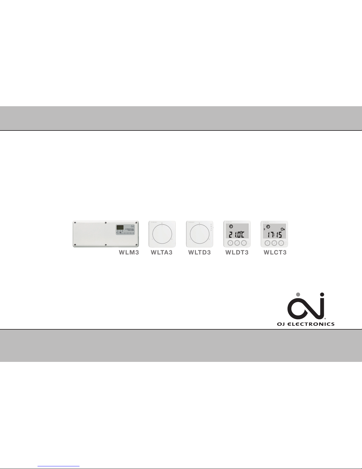
WLDT3
WLM3
WLCT3
WLTD3
WLTA3
Installation Quick Guide
www.ojelectronics.com
67347 02-15 (HKT)
Page 2

2
© 2015 OJ Electronics A/S
Installation Quick Guide ............................................................................................................ Page 3
Setting up the system .............................................................................................................. Page 5
Wireless system only ............................................................................................................... Page 5
Testing the system .................................................................................................................. Page 6
Troubleshooting ..................................................................................................................... Page 7
CONTENTS
QUICK GUIDE
Page 3

3
© 2015 OJ Electronics A/S
We recommend that the zone chart on the back page of the user manual be filled in before
commencing installation. This will identify the piping circuits to specific rooms and enable the correct
allocation of channel numbers in the WLM3 system.
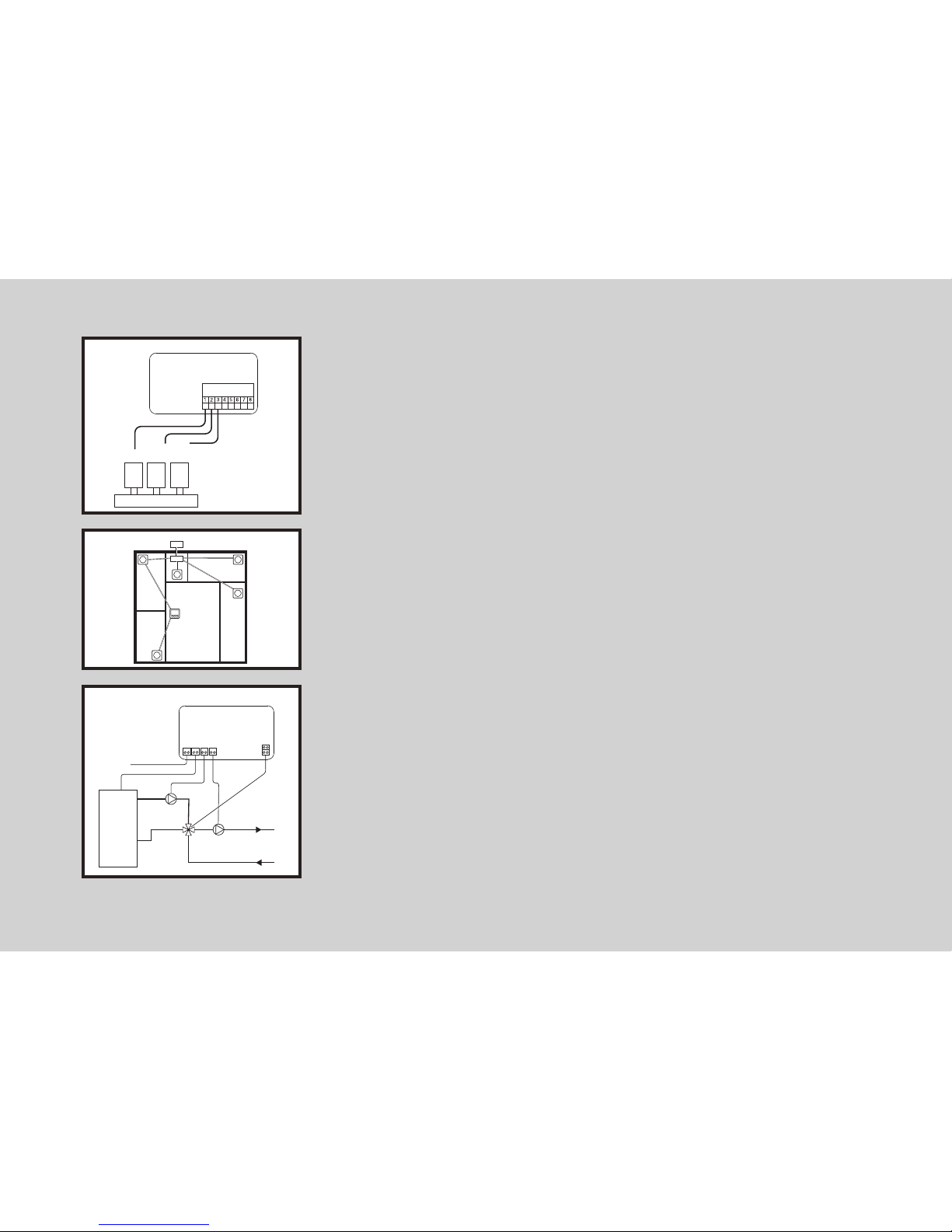
Mount the master and any AO module correctly on the wall in accordance with electrical regulations.
Connect the AO module using the special cable included in the box.
Mount the room sensors/controllers in the rooms, and set their channel selectors to correspond to the
number of the actuator controlling the room concerned.
With hardwired room sensors/controllers, connect the 2-wire bus to the master or AO module,
maintaining continuity of positive (+) and negative (-) connections.
If the room sensors/controllers are of wireless type, connect the receiver (WLRC3) using the special
cable included in the box.
NB: For room sensors/controllers with floor temperature limitation sensors, please refer to the
separate instructions included with the unit.
INSTALLATION QUICK GUIDE
A
B
D
C
QUICK GUIDE
This Quick Guide is for reference only and is not suitable for networked installations.
For full installation details, please refer to the full Installation Manual.
BR1025A15a
© 2015 OJ Electronic A/S
WLM3-BA/FS Master
WLM3-AO Module
BR1025A15a
BR1025A04a
© 2015 OJ Electronic A/S
WLM3 - Master
WLRC3
BR1025A04a
BR1025A05a
© 2015 OJ Electronics A/S
Channel 1
Manifold
Actuator 1
Actuator 2
Actuator x
Channel
selector
-GB
Jumper
BR1025A05a BR1025A16a
BR1025A16a
© 2015 OJ Electronic A/S
WLM3-BA/FS Master
WLM3-AO Module
AO Module Cable
With wireless room controllers/sensors, remove the front cover and before mounting the unit but do
not remove the plastic battery pull tab. Complete wireless setup before removing the plastic battery
pull tab and refitting the front cover.
Page 4
4
© 2015 OJ Electronics A/S
Connect the actuators to the channel outputs on the master in accordance with the pipe manifold
layout (see the zone chart).
Connect actuator no. 1 on the manifold to output no. 1 on the master.
Connect actuator no. 2 on the manifold to output no. 2 on the master.
etc.
Outdoor compensation module WLOC3 (FS masters only)
Install on wall facing away from direct sunlight.
Connect to 2-wire room sensor bus or direct to master, maintaining continuity of positive (+) and
negative (-) connections.
Connect 230V AC power supply, UFH circulating pump and boiler in accordance with
electrical regulations. (With FS masters, connect the mixing valve and supply water
temperature sensor.)
F
G
E
BR1025A17a
© 2015 OJ Electronic A/S
WLM3 - Master
Manifold
Actuator 1
Actuator 2
Actuator x
-GB
Thermal
Actuators
BR1025A17a
BR1025A13a
© 2015 OJ Electronic A/S
WLOC 3
Master
BR1025A13aBR1025A23a
WLM3 MASTER
BR1025A23a
© 2015 OJ Electronic A/S
-GB
FLOW DIAGRAM
Power
supply
Mixing Valve
Actuator
Main pump
Secondary pump
BOILER
Page 5

5
© 2015 OJ Electronics A/S
SETTING UP THE SYSTEM
1. Turn on the power and perform a full reset of the master by pressing the OK button for 16 seconds until all the area LEDs flash alternately
(the unit must be in DAY temperature mode - sun symbol).
2. Set the clock on any WLCT3 room controller.
2.1. If the hour digit is not flashing, press the small pinhole button beside the clock symbol.
2.2. Adjust the hours and press OK.
2.3. Adjust the minutes and press OK.
2.4. Adjust the day number (1 = Monday) and press OK.
3. In addition to the settings for its own room, the WLCT3 room controller can be used to set the operating times and temperatures of other room sensors
(channels).
To achieve this, do the following on the WLCT3 room controller:
3.1. If “CH 1” is already shown on the display of the WLCT3 room controller, proceed directly to step “3.4”.
3.2. Press the UP and DOWN buttons simultaneously for 4 seconds to enter the “InFo” menu.
3.3. Press the UP and Down Buttons to locate the “ArEA” menu and then press OK.
3.4. The display now shows “CH 1” (channel 1).
- Press the OK (√) button.
- Select “On” if this channel (room sensor) is to be controlled by the WLCT3 room controller by pressing the ‘DOWN’ button, otherwise select “OFF”.
- Now press the OK button to go to the next channel (CH 2) and repeat this step until all the required channels have been set.
3.5. After all channels have been set, select the “ESC” menu entry and press OK.
NB: If dierent times and temperatures are required for other channels (room sensors) within the system, more than one WLCT3 room controller can be
used. Care must be taken to ensure that a channel is not set to “On” on more than one WLCT3 room controller.
ADDITIONAL STEPS FOR WIRELESS SYSTEM:
Learning mode button
BR1026A09a
© 2015 OJ Electronic A/S
Channal
selector
-GB
Jumper
Button learning
mode
BR1026A09a
BR1025A10a
© 2015 OJ Electronic A/S
9
10
-GB
ON
OFF
Common UHF-PUMP
Commission mode
X-RELAY
Learn mode
Boiler test
Install mode
WLM2 Compatible
ON / OFF Control
BR1025A10a
4. Switch on DIP-3 to activate learning mode.
5. All wireless room sensors/controllers must now be initialized:
- Initialize analogue room sensors (WLTA3, WLTD3, WLTM3) by
removing the plastic battery pull tab or pressing the internal
initialization button (learning mode button) until a beep is heard.
- Initialize digital room sensors/controllers (WLCT3 and WLDT3) by
pressing the pinhole button (learning mode button) beside the clock or
I until a beep is heard.
When communication with a room controller/sensor has been
established, the corresponding channel LED on the master will light up.
6. Switch o DIP-3 to deactivate learning mode:
Page 6

6
© 2015 OJ Electronics A/S
1. Switch on DIP-3 to activate learning mode. - the power LED will flash quickly
2. Each red channel LED on the master should now be lit if a room sensor/controller is present on
that channel.
3. Switch o DIP-3 to deactivate learning mode again – the power LED will stop flashing.
4. Set the setpoint on all adjustable room sensors/controllers to minimum.
5. Switch on DIP-1 on the master to activate install mode. Install mode will remain active for 2
hours. Pumps, boiler, mixing valve and actuators should now be OFF.
NOTE: During install mode, the boiler will not fire unless DIP-2 is also activated. This is
designed to reduce energy consumption and boiler cycling during the testing process.
6. Set the knob on the adjustable room sensor/controller in room 1 to maximum. The red channel
1 LED should light up and the actuator on output 1 should activate.
Important: If the room sensor/controller is of wireless type, a delay of up to 5 minutes may
occur before the channel LED lights up. (Pressing the initialization button inside the room
sensor/controller for 30 sec. speeds this up.)
7. With an FS master, check that the UHF pump starts running and that the mixing valve opens.
8. Repeat step 6 for all rooms.
9. Boiler test function:
Switch on DIP-2.
This activates the boiler relay contacts for 1 minute.
10. To end system testing:
- Switch o DIP-1 to deactivate install mode.
Switch o DIP-2 to deactivate the boiler test.
- Set all temperature knobs to default positions.
Set WLTA3,WLTD3,WLTM3 and WLDT3 room sensors to zero (centre position /no oset).
Set WLCT3 room controllers to 21°C (recommended).
- Set all WLTM3, WLTD3 and WLDT3 room sensors to automatic mode (clock symbol).
11. The system will now operate automatically.
Other important settings can be found in the User Manual.
TESTING THE SYSTEM:
Page 7

7
© 2015 OJ Electronics A/S
TROUBLESHOOTING:
Problem Possible cause & solution
Channel LED does not light up
(when in learning mode)
Check that the power LED is flashing quickly. If it is not, switch DIP-3 to ON position.
2-wire bus may be incorrectly connected. Voltage at each room sensor should be no lower than 4.0V (check
for + & - continuity and short circuits).
With wireless room sensors, check that the batteries have been inserted correctly.
With wireless room sensors, check whether the initialize button has been pressed.
With wireless room sensors, check that the WLRC3-19 (receiver) has been connected correctly.
If the LEDs for channel 9-14 do not light up, check that the AO module has been connected to the master
correctly.
Check that the room sensor in the room has been set to the correct channel number.
The channel selector on the room sensor may be slightly out of position, try rotating it and then set it again.
Channel LED does not light up
(when in install mode after the room sensor
has been activated (set to maximum))
........................................................................................................................
The master itself has cancelled install mode. After 2 hours the master automatically de-activates install
mode. Reset DIP-1.
Check that the room sensor in the room has been set to the correct channel number (two room sensors
might be interchanged).
The actuator on the manifold does not
open after 3 minutes
Check that the red channel LED is lit (if not, see above).
The actuator for the room is not connected to the correct output on the master.
Bad electrical connection between actuator and terminals.
The actuator may be faulty or manually locked.
UFH pump does not start in install mode
Bad electrical connection between pump and terminals.
Install mode has not been activated. Move DIP-1 to the OFF position and then back to the ON position.
The pump may be faulty.
Page 8

8
© 2015 OJ Electronics A/S
Output relay for main pump, cooling, highlimit valve or other attached device not
activated
Incorrect connection to device (X-OUTPUT relay has volt-free contacts, see master wiring diagram for correct
connection).
Bad electrical connection between attached device and terminals.
Install mode not activated, set DIP-1 to OFF and then back to the ON position to commence install mode for
2 hours.
The attached device may be faulty.
Dip switches may be incorrectly set, see “Free Relay Function (X-OUTPUT)” in the Installation Manual for
details.
Boiler does not fire
(LED lit)
Incorrect connection to boiler (X-OUTPUT relay has volt-free contacts, see master wiring diagram for
correct connection).
Bad electrical connection between boiler and terminals.
During install mode the boiler relay will not operate.
The attached boiler may be faulty.
(LED not lit)
..................................................................................................................................................
Timing sequence delay is activated.
FS master only - mixing valve not open more than 20%.
No heat demand from room sensors.
Master is in cooling mode.
Mixing valve does not operate correctly
(when in install mode)
Incorrect connection, see master wiring diagram for correct connection.
Incorrect valve/actuator assembly.
The actuator is faulty.
Check what happens if the sensor and/or outdoor module are removed.
(valve cycles between open and closed
in normal operating mode)
....................................................................................................................................
Valve may be oversized.
Supply water sensor may be subject to heat migration.
Upstream water temperature is excessively high.
(These problems can be corrected by changing PI settings – please refer to the main installation manual).
Incorrectly installed, see the installation instructions supplied with the actuator.
Page 9

9
© 2015 OJ Electronics A/S
Room is too cold
(after running for at least 48 hours)
The room sensor is placed in a position that does not represent the general temperature in the room. For
example mounted on an external wall or near to an external heat source.
If the room is controlled by a WLCT3 room sensor, check that the time and temperatures are set correctly.
If the room sensor has a mode switch (WLTM3, WLTD3 or WLDT3), the switch may be set to “OFF” or
“NIGHT” position.
For rooms with floor sensors, the maximum floor limit setting could be preventing the room from reaching
the desired temperature.
The system may have insucient heating capacity.
Poor insulation may be causing large heat loss.
Room is too hot
(after running for at least 48 hours)
This might be caused by draughts caused by internal wall cavities or open doors or windows which aect
the temperature-measuring ability of the sensor.
The room sensor is placed in a position that does not represent the general temperature in the room.
If the room is controlled by a WLCT3 room sensor, check that the time and temperatures are set correctly.
If the room sensor has a mode switch (WLTM3, WLTD3 or WLDT3), the switch may be set to the “DAY”
position.
For rooms with floor sensors, the minimum floor limit setting could be maintaining the room temperature
above the desired setting.
Solar gain or an external heat source.
Temperature is unstable This could be caused by periodic solar gain or external heating. Try setting the master to simple ON/OFF
control (DIP-10 set to ON).
Page 10

10
© 2015 OJ Electronics A/S
Page 11

11
© 2015 OJ Electronics A/S
Page 12

OJ ELECTRONICS A/S
STENAGER 13B
DK-6400 SØNDERBORG
DENMARK
T. +45 73 12 13 14
F. +45 73 12 13 13
OJ@OJELECTRONICS.COM
WWW.OJELECTRONICS.COM
OJ ELECTRONICS UK
CRUSADER PARK
WARMINSTER
WILTSHIRE, BA12 8SP
UNITED KINGDOM
T. +44 01985 213 003
F. +44 01985 213 310
SALES@OJUK.CO.UK
WWW.OJUK.CO.UK
OJ ELECTRONICS A/S
C/O ROBERT BIELECKI
UL. WALBRZYSKA 33
58-160 SWIEBODZICE
POLSKA
T. +48 4220 91 742
F. +48 4220 91 744
RBI@OJ.DK
WWW.OJELECTRONICS.PL
The OJ trademark is a registered trademark belonging to OJ Electronics A/S · © 2015 OJ Electronics A/S
 Loading...