

Page 1
Type UCCG, UCDG
USER MANUAL
Product program
This user manual covers following thermostats with built-in GFCI
UCCG-9991 Incl. floor sensor 3m
UCCG-9999 With built-in room sensor
UCDG-9999 With 2 sensors; built-in room sensor and incl. floor sensor 3m
Introduction
The thermostat is an electronic on/off thermostat for control of temperature by means of an NTC sensor either placed externally or internally in the thermostat. The
thermostat has integrated a Ground Fault Circuit Interrupter (GFCI, Class A). The thermostat and the GFCI is a dual model suitable for 120/240 V 50/60 Hz supply.
The thermostat is capable of switching on your heating system at pre determined times on different days of the week. It is possible to set 4 periods called events
each day with different temperatures. From factory a default schedule is programmed suitable for most installations. Unless you change these settings the
thermostat will operate to this default program. Working with lower temperatures during times that the room is unoccupied will lower your energy costs without
reducing the comfort. The thermostat has an adaptive function that automatically changes the start time of a heating period so that the desired temperature is
reached at the time that you set. After 5 days the adaptive function has learned when the heating must be switched on.
The thermostat type UCCG-9991 has an external temperature sensor that is normally placed in the floor construction. In this configuration the thermostat
controls the temperature of the floor and not the temperature within the room.
The thermostat type UCCG-9999 has a built-in temperature sensor. In this configuration the thermostat controls the temperature of the room.
The thermostat type UCDG-9999 has a built-in temperature sensor and an externally temperature sensor. In this configuration the thermostat
controls the temperature within the room and use the externally temperature sensor as limit sensor avoiding too high or too low temperatures in the floor
construction.
The thermostat has a pin button marked R, allowing you to reset the thermostat to factory settings. These are listed at the end of this manual with space for
you to record your own weekly schedule.
GFCI
Test
R
Reset
®
BR928A08
A
B
C
D
E
F
H
I
G
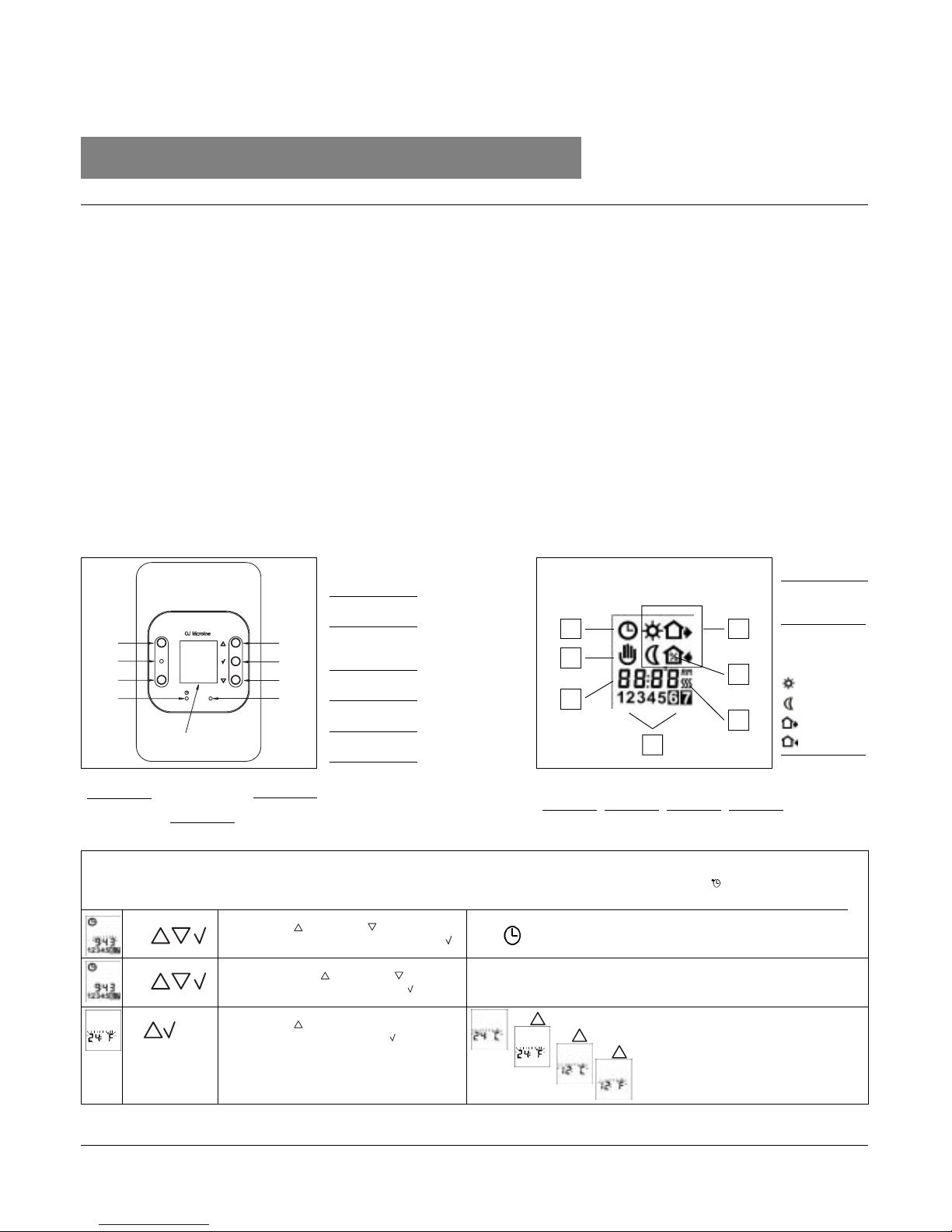
Buttons
Display symbols
P
O
N
M
J
K
L
1. Getting started
Wake
Night
Out
Home
A:
Reset of GFCI
F:
Reset to factory
setting
G:
Adjustment down
H:
OK - accept
I:
Adjustment up
B:
Red light
indicating
ground fault
C:
Test of GFCI
D:
Pin button
adjust of clock
E:
Display
J:
Clock
function
K:
Manual
mode
L:
Time and
temperature
M:
Day
number
N:
Heating on
O: %
Monitoring of
switch-on time
P:
4-event
symbol:
Setting the thermostat into operation
☞
☞
☞
1-7
Press the UP ( ) or DOWN ( ) buttons to
select the correct time and press OK button ( ).
Then press the UP ( ) or DOWN ( ) button to
select the correct day and press OK ( ) button.
Press the UP ( ) button to select time and
temperature scale and press OK ( ) button.
First time power is connected the clock and day will be flashing and must be set. After setting of time and day, selection of time scale (12 h or 24 h) and
temperature scale (°C or °F) can be selected. If you need to adjust the time of the thermostat at a later date, insert a pin into the hole ( ) for setting of time and
day. Adjustment must be made for summer and winter time. Setting of time and temperature scale can also be done under "advanced settings and r ead-out see 4.
☞
☞
☞
Lagernummer: 57611 08/03 - (BJ)
Type: UCCG, UCDG
Page 2

Checking GFCI
It is important that the GFCI has been checked for correct installation and function.
To check the GFCI: Testing can only be performed if the thermostat has a heating demand. Adjust the set point until the heating symbol (SSS) appears, use the
( ), to increase the heating demand. Wait 10 secs. to let the thermostat work according to the new set point. Press the button "TEST". The test is conclusive if
the red light on the thermostat lightens, and the display signs disappear. If this does not occur, check the installation. Press on RESET button to reset the GFCI.
The red light should disappear and the display will return to normal appearance. Push ok accept button ( ) to cancel the previously set temperature. If the test
fails, check your heating cable and the thermostat. The GFCI test should be carried out monthly.
If the GFCI trips in normal operation, without pressing the TEST button, there could be a ground fault! To check whether it is a ground fault or a nuisance
tripping, press RESET. If this cause the red light to shot off and not comes on again, it was a nuisance tripping and the system is functioning. If this cannot be
done there is a ground fault! Check your heating cable, the sensor cable and the thermostat.
Exchange the defective part.
2. Daily use of the thermostat
4-event clock mode
The day has been split into 4 events describing a typical day. When the thermostat is in 4event mode it will automatically adjust the temperature according to the required temperature
to the required time. As standard the thermostat has 5 days with 4 events, and 2 days with 2
events. Programming see 3.
4-event clock mode:
Comfort mode:
☞
☞
Manual mode:
☞
☞
Temporary override
To temporarily override the temperature in the 4-event schedule program, press the UP ( ) or DOWN ( ) button
once, to show the temperature, and press again to increase or decrease the temperature. The display will flash for 5
seconds, and will then revert to the time. The override will operate until the next programmed event when the unit will
resume the automatic programme.
The clock function symbol ( ) and one of the 4-event symbols ( ) will be indicated.
Programming see 3.
Cancel comfort mode
To cancel the override state, press the OK ( ) button twice.
Permanent override:
During holidays, the scheduled 4-event program can be overridden. Press the OK ( ) button, and then the UP ( ) or
DOWN ( ) button until the override temperature is set. The unit will now operate to this temperature permanently.
Cancel manual mode
To cancel the permanent override state press the OK ( ) button once, and the unit will resume automatic function.
5 secs.
5 secs.
☞
☞
☞
☞
☞
☞
☞
☞
Press OK ( ) button for 3 secs. to begin programming
: Time and temperature
: Time and temperature
: Time and temperature
: Time and temperature
Day 1 - 5
Day 6 - 7
☞ ☞
: Time and temperature
☞ ☞
: Time and temperature
3. Programming
4-event time and temperature
For each event, the start time and required temperature must be
set.
For example, in the morning you wish the heating to start at
07:00 and the temperature to rise to 25˚C. Press OK ( ) button
for 3 seconds and the start time is displayed. Change this to
07:00 with the
UP ( ) or DOWN ( ) button. Press OK ( ) to confirm.
The temperature is now displayed. Change this to 25˚C with the
UP ( ) or DOWN ( ) button.
Press OK ( ) button to confirm. This action can now
be repeated for the second event.
These settings will be valid with days 1-5 showing on the
display. To program the days 6 and 7, repeat the above. Days 6
and 7 are usually Saturday and Sunday, and only have two
events.
The temperature can be set within the range of +5 to +40˚C. It is
also possible to select the heating OFF at that event by
reducing the setting to 5˚C, and then pressing the ( ) once
more.
Page 3

Monitoring of energy consumption. The thermostat calculates average time it has been switched on allowing you to monitor your energy
consumption. In the thermostat you can read out:. Total switch-on time in percentage in the latest 2 days, 30 days or 365 days.
Calculation of operational costs per day: (switch-on time:100) x kW x kWh-price x 24 h per day
Example: Read-out: 30 % in the latest 365 days
Size of heating system: 1,2 kW (ask the installer)
Cost of power: 0,2 USD/ kWh - Calculation: (30:100) x 1,2 kW x 0,2 USD/ kWh x 24 h = 1,7 USDper day
4. Advanced settings and read-out
4-event sequence. The present event sequence flashes: Days 1-5, followed by days 6-7. To change, press the UP ( ) button until you
have days 1-6 and then day 7 flashing, or all 7 days are flashing. Select the required sequence with the OK ( ) button.
☞
✚
☞
☞
5-2: 4 events in 5 days +
2 events in 2 days.
6-1: 4 events in 6 days +
2 events in 1 day
7-0: 4 events in 7 days
☞
☞
}
2 days
30 days
365 days
Software version
Actual sensor temperature
}
Max and min allowed temperature range. The temperature setting range of +5˚ to 40˚ C can be limited to prevent a too high or too low
temperature being selected. For example, a wood floor covering should not be allowed to exceed a maximum of 27˚C. Low limitation is
used where the temperature of the floor is required never to fall below the minimum set temperature.
Time and temperature scale selection
Adaptive function: This function enables the thermostat to calculate when it needs to switch ON so that the required temperature is
reached at the set time. With a start time of 07:00 therefore, the thermostat may switch ON as early as 06:00 so that the desired
temperature of 25˚C is achieved by 07:00. Without this function set, the thermostat will start to heat at the time you set.
☞
☞
☞
☞
Maximum allowed temperature setting. Use the UP ( ) or
DOWN ( ) button to increase or reduce, and OK ( ) button to
accept.
Next is displayed LoLi. Press OK ( ) button to continue.
Minimum allowed temperature setting. Use the UP ( ) or
DOWN ( ) button to increase or reduce and OK ( ) button to
accept.
You can select either ˚C or ˚F scale, and 12 or 24 hour clock as
follows:
Press UP ( ) or DOWN ( ) button to change settings.
Confirm the required scale with the OK button ( ) button.
☞
☞
}
}
☞
☞
☞
☞
☞
Press the DOWN ( ) button to switch between on and off.
Press OK ( ) button to confirm.
Press OK ( ) button to end programming and to return to
scheduled programme.
☞
☞
☞
☞
Press both UP ( ) and DOWN ( ) buttons together for 3 seconds. INFO is displayed.
Press UP ( ) button until you reach the desired sub menu. Select the sub menu with the OK ( ) button.
Press UP ( ) or DOWN ( ) button to show the different readouts.
No changes can be made here. Use the OK ( ) button to end.
Page 4
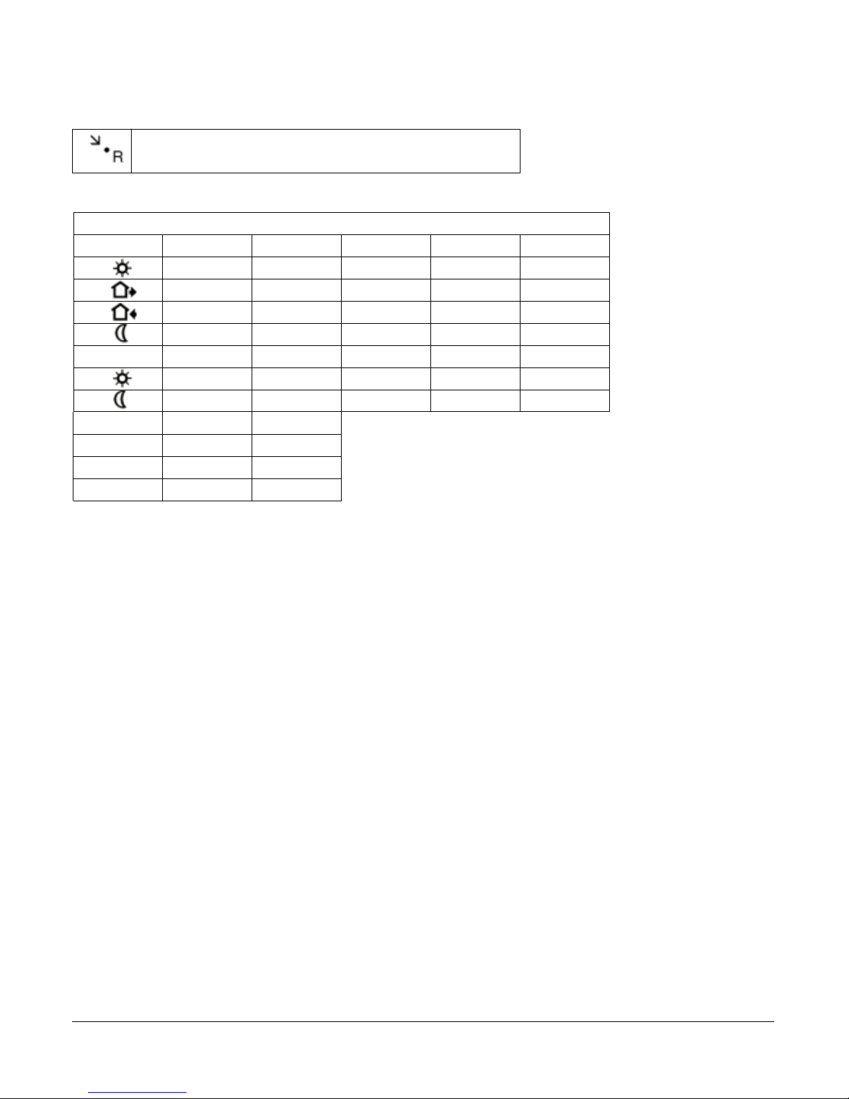
Press the pin button for 3 secs. and the thermostat returns to factory settings. Time,
day and scale for time (12h, 24h) and temperature (˚F, ˚C) read-out are also reset and
must be set according to “Setting the thermostat into operation”.
5. Reset to factory setting
4-event time and temperature
Day 1-5
06:00
Time With floor sensor Built-in sensor
08:00
16:00
22:30
08:00
23:00
5:24-event sequence
131˚F / 41˚F
24 H / ˚F
ON
Hi-Low temp.
Scale
Adaptive control
Day 6-7
77˚F / 25˚C 68˚F / 20˚C
68˚F / 20˚C 59˚F / 15˚C
81˚F / 27˚C 72˚F / 22˚C
68˚F / 20˚C 59˚F / 15˚C
81˚F / 27˚C 72˚F / 22˚C
68˚F / 20˚C 59˚F / 15˚C
6. Failure codes
E0 = Internal failure, replace thermostat
E1 = Built-in sensor short-circuit or disconnected,
replace thermostat
E2 = External sensor short-circuit or disconnected
7. Technical data
Supply: . . . . . . . . . . . . . . . . . . 120/240 Vac 50/60 Hz
Load: . . . . . . . . . . . . 16A maximum (resistive load)
Power: . . . . . . . . . . . . . . . . . . . . 1.920 W at 120 Vac
3.840 W at 240 Vac
GFCI: . . . . . . . . . . . . . . . . . Class A (5 mA trip level)
Temperature range: . . . . +5 to +40°C, +40 to +104˚F
Amb. Temperature range:
Thermostat: . . . . . . . . . . . 0 to +40°C, +32 to +104˚F
GFCI: . . . . . . . . . . . . . -35 to +65°C, -31 to +149˚F
OJ ELECTRONICS A/S
Stenager 13B · DK-6400 Sønderborg
Tel. +45 73 12 13 14 · Fax +45 73 12 13 13
www.oj.dk
Factory settings
Page 5

Type UTCG, UCCG, UCDG
INSTRUCTIONS
Lagernummer: 57609 - 08/03 (BJ)
English
The thermostat is an electronic on/off
thermostat for control of temperature by means
of an NTC sensor either placed externally or
internally in the thermostat. The thermostat has
integrated a Ground Fault Circuit Interrupter
(GFCI, Class A). The thermostat and the GFCI is
a dual model suitable for 120/240 V 50/60 Hz
supply.
The thermostat is for flush mounting in a wall
socket.
Product program
Thermostats with built-in GFCI
UTCG-9991 Incl. floor sensor 3 m
UTCG-9999 With built-in room sensor
Clock-thermostats with built-in GFCI
UCCG-9991 Incl. floor sensor 3m
UCCG-9999 With built-in room sensor
UCDG-9999 With 2 sensors;
built-in room sensor and
incl. floor sensor 3m
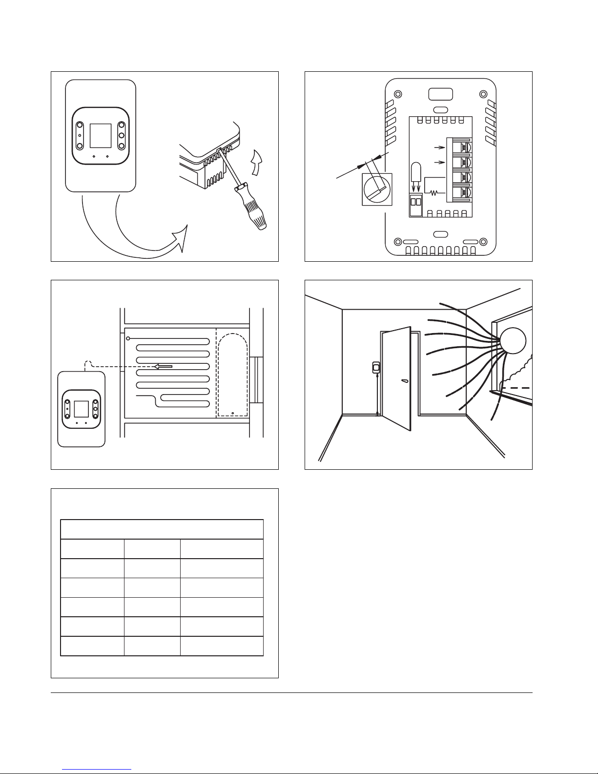
Mounting of floor sensor (fig. 3)
The floor sensor is used for temperature
regulation in floor surfaces. For easy
replacement the sensor can be mounted in a
tube which is placed between 2 heating cables.
The tube is ended towards the floor surface and
sealed.
If required, the sensor cable can be extended
up to about 100 m with a standard installation
cable. 2 leads in a multi lead cable, which is
used as supply cable for the heating cable,
must not be used.
Mounting of thermostat with built-in sensor
(fig. 4)
The room sensor is used for comfort
temperature regulation in rooms. The
thermostat is mounted on the wall with free air
circulation about 1.6 m above the floor. Draught,
direct sunlight, or any other direct heating outlet
must be avoided. No external sensor is to be
connected.
Mounting of thermostat
Installation
TURN OFF THE POWER TO THE HEATING
SYSTEM AT THE MAIN POWER PANEL TO
AVOID ELECTRICAL SHOCK.
KEEP AIR VENTS OF THE THERMOSTAT
CLEAN AND OBSTRUCTION FREE.
This thermostat is an electrical product and
must be installed in conformity with the National
and/or Local Electrical Code. The installation
must be performed by qualified personnel
where required by law. The thermostat is
equipped with a ground fault circuit interrupter
(GFCI, Class A), which require that the line and
load is isolated from each other for correct
operation. The resistive load must not exceed
16A (1920W at 120Vac /3840W at 240Vac).
During a ground fault, the two lines will be cutoff.
Line Cable
Delivers power from the service panel (breaker
panel or fuse box) to the thermostat.
This cable shall only be connected to the
thermostat’s line terminals marked L1 and L2.
Load Cable
Delivers power from the thermostat to the
heating cable.
This cable shall only be connected to the
thermostat’s load terminals marked load, 16A.
1. Use a screwdriver to open the lock (fig. 1),
and remove the frame
2. Connect cables according to the diagram
(fig. 2)
3. The thermostat is mounted in the wall socket.
The frame are remounted.
Temperature sensor
The floor sensor is connected to the screw less
terminals marked sensor. Push with a
screwdriver on the terminal spring and mount
the wires.
Operation
With integrated clock, type UCCG and UCDG:
The first time the thermostat is connected,
time and day must be set:
Setting of time (the clock flashes
during setting)
Setting of day (day flashes during
setting)
Without integrated clock, type UTCG:
Actual temperature setting is shown and the
thermostat is ready for use.
Checking GFCI
It is important that the GFCI has been checked
for correct installation and function.
To check the GFCI:
Testing can only be performed if the thermostat
has a heating demand
Adjust the set point until the heating symbol
(SSS) appears, use the ( ),
to increase the heating demand. Wait 10 sec to
let the thermostat work according to the new
set point.
Press the button "TEST"
The test is conclusive if the red light on the
thermostat lightens, and the display signs
disappear. If this does not occur, check the
installation.
Press on RESET button to reset the GFCI.
☞
☞
BR928A10
Type: UTCG, UCCG, UCDG
The red light should disappear and the display
will return to normal appearance.
Push ok accept button ( ) to cancel the
previously set temperature
If the test fails, check your heating cable and
the thermostat.
The GFCI test should be carried out monthly.
If the GFCI trips in normal operation, without
pressing the TEST button, there could be a
ground fault! To check whether it is a ground
fault or a nuisance tripping, press RESET. If this
cause the red light to shot off and not comes on
again, it was a nuisance tripping and the system
is functioning. If this cannot be done there is a
ground fault!
Check your heating cable, the sensor cable and
the thermostat. Exchange the defective part.
Programming
See user’s manual.
Fault location
If the sensor is disconnected or short-circuited,
the heating system is cut out. The sensor can
be checked according to the resistance table
fig. 5.
Error codes
E0: Internal error. The thermostat must be
replaced.
E1: Built-in sensor short-circuited or
disconnected. The thermostat must be
replaced
E2: External sensor short-circuited or
disconnected.
UL LISTED
According to the following standards,
GFCI: UL 943:1993
Thermostat: UL 8730-2-9:1998
UL 60730-1A:2002
UL file number: E157297.
Classification
The product is a class II device (enhanced
insulation) and the product must be connected
to the following leads:
Phase (L, L1) 240 V ±15%, 50/60 Hz or
120 V ±15%, 50/60 Hz
Neutral (N, L2)
Load max. 16A
The terminals are suitable for field wiring of 12
AWG to 22 AWG conductors
Technical Data
Supply . . . . . . . . . . . . . .120/240 Vac 50/60 Hz
Load . . . . . . . .16A maximum (resistive load)
Power . . . . . . . . . . . . . . . .1.920 W at 120 Vac
. . . . . . . . . . . . . . . .3.840 W at 240 Vac
GFCI . . . . . . . . . . . .Class A (5 mA trip level)
Temperature range .+5 to +40°C, +40 to +104˚F
Amb. Temperature range
Thermostat . . . . . . . .0 to +40°C, +32 to +104˚F
GFCI . . . . . . . . .-35 to +65°C, -31 to +149˚F
Page 6
BR928A06
Fig. 1
BR928A02
Fig. 3
BR928A07
Sensor
Temp.(˚C)
Value (ohm)
-10
0
10
20
30
64000
38000
23300
14800
9700
Temp.(˚F)
68
86
50
32
-14
Fig. 5
1/4"
1/4" Strip
length
BR928A05
L1
L2
120/240VAC
16A
1920W /
SENSOR
3840W
Fig. 2
1,6m
Fig.4
 Loading...