

Page 1

INSTRUCTIONS
Type PTH
57433B 03/14 (OSH)
English
PTH is a series of electronic pressure transmitters designed primarily to measure total and
differential air pressures in ventilation systems.
The resulting measurements are used for
monitoring, control and regulation purposes via
a regulator, PLC or monitoring system. The resulting measurements are used for monitoring,
control and regulation purposes via a regulator,
PLC or monitoring system.
Typical applications include:
- The maintenance/control of constant pressure
at a given position within the duct system.
- The maintenance/control of desired underpressure within the duct system.
- The measurement of pressure differentials
across filters to determine optimum filter
replacement time.
- Flow determination via differential pressure
measurements across a standard aperture.
PRODUCT PROGRAMME
Type Product
PTH-3202 Pressure transmitter,
0-2500 Pa, 1 channel, IP54
FUNCTION
PTH is a pressure transmitter for comfort
ventilation systems. It provides an active current
or voltage signal proportional to the measured
air pressure. PTH consists of semiconductor elements. There is no air throughput and
the unit is thus protected against dust in the
ventilation system. The pressure element is
temperature compensated to provide accurate
pressure measurement throughout the specified
temperature range.
The required measuring range of the pressure transmitter is set with DIP switches. The
output signal can be changed from voltage
[V] to current [mA] by setting a jumper. A DIP
switch allows two different damping times to be
selected so that pressure fluctuations within the
ventilation system are attenuated in the transmitter output signal. A green LED indicates that
supply voltage has been connected correctly.
If the actual pressure is outside the selected
measuring range, the green LED flashes.
CE MARKING
OJ Electronics A/S hereby declares that the
product is manufactured in accordance with
Council Directive 92/31/EEC on electromagnetic compatibility (and subsequent amendments)
and Council Directive 73/23/EEC on electrical
equipment designed for use within certain
voltage limits.
Applied standards
EN 61000-6-2 and EN 61000-6-3
Electromagnetic compatibility (EMC)
TECHNICAL DATA
Full scale pressure range PTH-3202 / 0-2500 Pa
Pressure ranges ................ PTH-3202 (see fig. 5)
Supply voltage ............24 V AC ±15%, 50/60 Hz
13.5-28 V DC
Own consumption (-20/+40°C) ...... max. 0,5 VA
Output signal (selectable) ................. 0-10 V DC,
2-10 V DC
4-20 mA, 0-20 mA
Accuracy output signal ........................................
1.5 %xMV+0.3 %xSR+2.5 Pa
(MV = measured value / SR = set measuring range)
Dampening (selectable) ................. 0.4 s or 10 s
Max. pressure .......................................... 20 kPa
Ambient temperature ......................... -20/+40 °C
(constant operation)
-30/+50 °C (transient)
Dimensions .............75 x 36 x 91 mm (see fig. 1)
Cable dimensions ................. 4 x max. 1.5 mm2
Pressure connector ........................ 2 x ø6.2 mm
Enclosure ..................................................... IP54
MOUNTING
PTH must be securely mounted on a level surface using screws. PTH is insensitive to mounting
orientation. However, in order to maintain the
specified enclosure, tubes should be attached
to both tube connectors if the connectors point
upwards. The enclosure is equipped with screw
holes, see fig. 1.
Pressure is connected by means of tubes.
The higher pressure must be connected to the
“+ connector” and the lower pressure to the
“- connector”. If the tubes are unintentionally exchanged, or the pressure is outside the
measuring range, the green LED flashes. See
table 1. The pressure tubes must be as short
as possible and must be secured in position to
prevent vibration. To obtain the best possible
results, pressure must be measured where
there is least risk of turbulence, i.e. in the centre
of the ventilation duct and at a suitable distance
from bends and branches. See fig. 2.
The enclosure is opened without the use of
tools by pressing the snap lock at the side of
the connectors. The transmitter cable may be
up to 50 m in length and must be connected as
shown in fig. 3. The transmitter cable must be
kept separate from mains-carrying cables as
voltage signals from these may affect transmitter function.
SETTINGS
Pressure range is set by turning the dial, SW2
(see fig. 3)
PTH types in this product series, pressure range
can be set to 8 different intervals, ranging from
-50/+50 Pa to 0-2500 Pa (see fig. 5).
If the dial is set to values other than the specified positions (0-7), the pressure transmitter will
interpret the setting as position 7 corresponding
to the highest pressure range.
If the pressure transmitter is inadvertently set
to a pressure range lower than the pressure
encountered in the connectors, the green LED
will light constantly (see table 1).
The screw terminals of the pressure transmitter
can provide a 0/2 - 10 V output signal and/or a
0/4 - 20 mA output signal (see fig. 4).
The 0-10 V output signal is provided by terminal
2 with DIP 1 of SW1 in position “Off”.
The 2-10 V output signal is provided by terminal
2 with DIP 1 of SW1 in position “On”.
The 0-20 mA output signal is provided by terminal 4 with DIP 1 of SW1 in position “Off”.
The 4-20 mA output signal is provided by
terminal 4 with DIP 1 of SW1 in position “On”
(see figs 4 & 7).
Output signal damping time can be set to 0.4
s or 10 s using DIP2 of SW1 (see figs 3 & 8).
The transmitter measures the pressure several
times within the set time and the output signal
consists of the average of these measurements.
This allows any pressure fluctuations within
the ventilation system to be dampened in the
transmitter output signal.
ZEROING
The transmitter can be zeroed after it has
been mounted and the power supply connected. Before zeroing the transmitter, it is
important to ensure that the pressure on the
+ and - connectors is equal (e.g. by stopping
the ventilation system). If the yellow LED is
constantly lit, the transmitter is measuring a
differential pressure of more than 50 Pa. This
may be caused by unintended pressure within
the system (draughts or compressed tubing). It
is recommended that tubes be removed from
the + and - connectors during zeroing. Zeroing
is activated by pressing the integrated zero-set
switch (see fig. 3), after which the yellow LED
will continue to flash until zeroing has been
completed.
LED INDICATION
The green LED is lit when the power supply has
been connected correctly and flashes when the
actual pressure is above or below the selected
measuring range. The yellow LED is lit if pressure exceeds 50 Pa and flashes for approx. 3
seconds during zeroing.
Table 1
LED on
On Flashing Off
Green OK
Yellow >0,5 mbar Zeroing in progress <0,5 mbar
FIGURES
Fig. 1: Dimensioned sketch
Fig. 2: Transmitter position in relation to bends
and branches
Fig. 3: PCB component positions
Fig. 4: Wiring diagram
Fig. 5: Selection of pressure range: PTH-3202
Fig. 6: Selection of output voltage/current
Fig. 7: Selection of damping time
Fig. 8: Free DIP switch
Bailey & Mackey Ltd
Baltimore Road
Birmingham B42 1DE
Tel: 0121-357 5351 · Fax: 0121-357 8319
www.baileymackey.com
Pressure outside
set range
No supply
© 2012 OJ Electronics A/S
1
Page 2
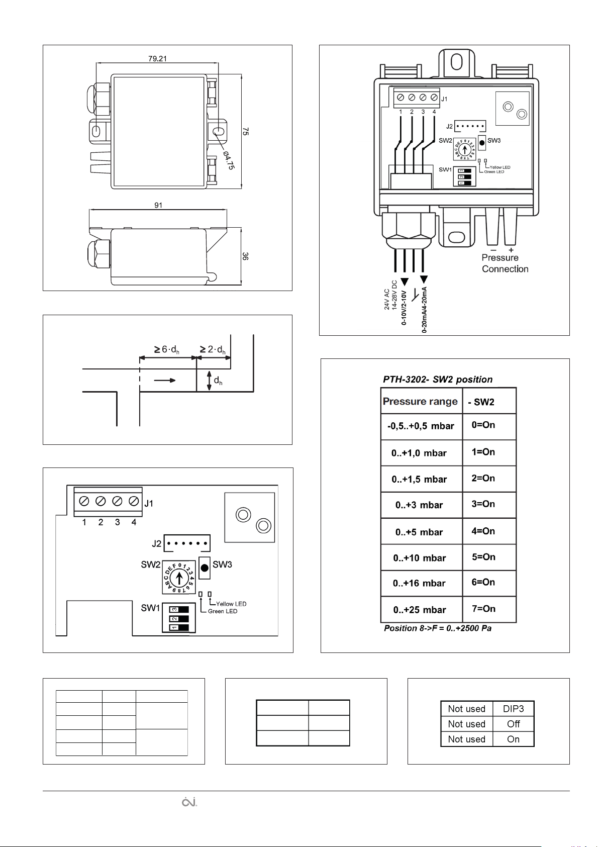
Fig. 1
BR-0996-A07
© 2011 OJ Electronics A/S
Output DIP1 Terminal
0-10 V O Terminal 2
2-10 V On
0-20 mA O Te rminal 4
4-20 mA On
BR-0996-A08
Fig. 2
Fig. 4
BR956A02bBR956A03aBR996A03
BR996A06
Fig. 3
Fig. 5
Fig. 6
2
Fig. 7
Fig. 8
Damping DIP2
0,4 Sec O
10 Sec On
BR996A07
The trademark is registered and belongs to OJ Electronics A/S · © 2014 OJ Electronics A/S
BR996A08
BR996A09 BR996B04
 Loading...