

Page 1
INSTRUCTIONS
© 2016 OJ Electronics A/S
1
67025D 07/16 (LOA)
Type OSD4-1999
English
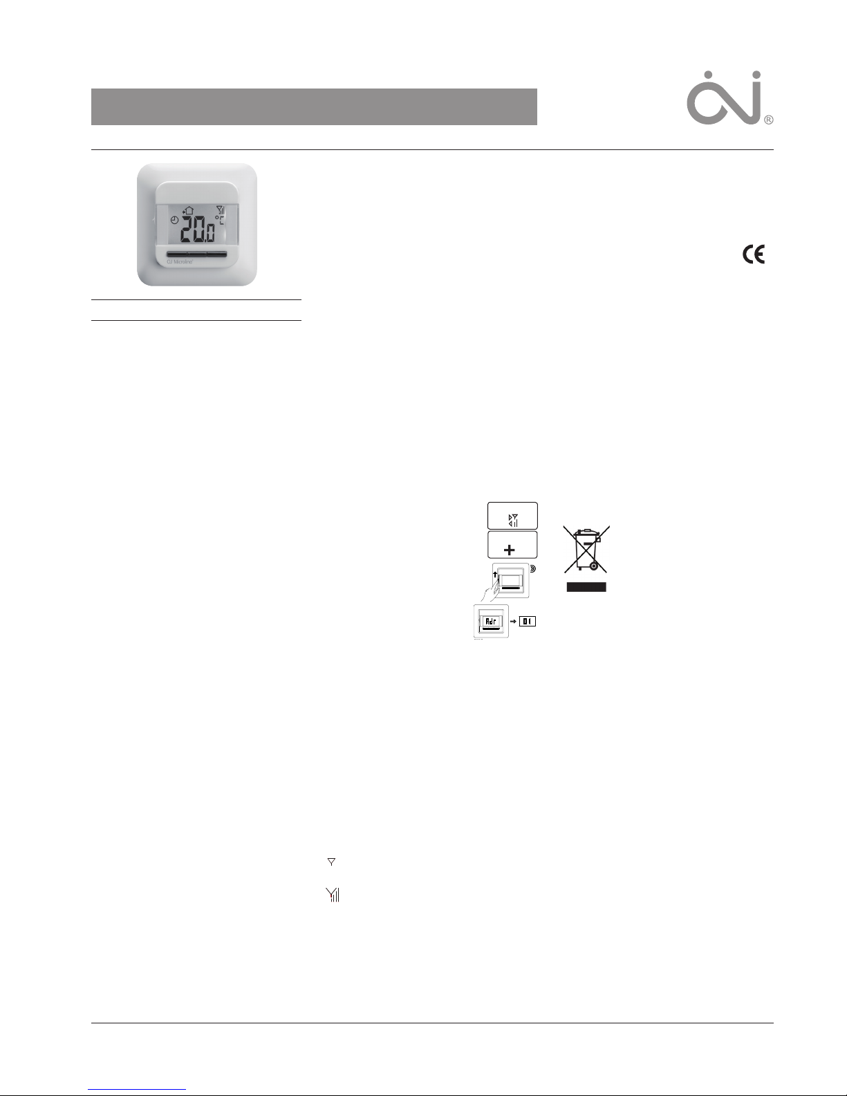
CS4TM THERMOSTAT
A wireless, radio controlled thermostat recommended for Comfort System 4. The thermostat is
ideal for all floor types and controls the heating
on the basis of room, floor or room/floor limit
temperature. Wireless communication to the central controller ensures easy installation.
PRODUCT PROGRAMME
OSD4-1999 Radio controlled thermostat with
built-in room sensor and floor sensor
WARNING – Important Safety Instructions
Disconnect the power supply before carrying out
any installation or maintenance work on this unit
and associated components. This unit and associated components should only be installed by
a competent person (i.e. a qualified electrician).
Electrical installation must be in accordance with
appropriate statutory regulations.
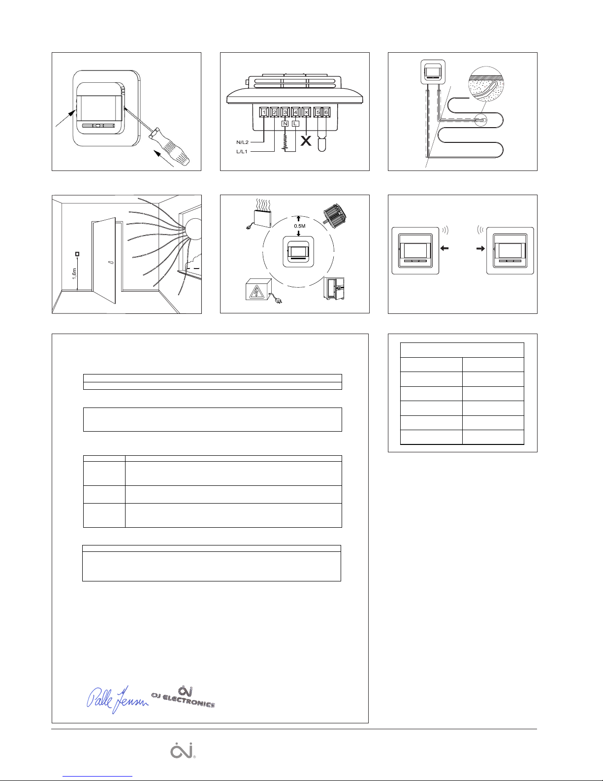
INSTALLING THE THERMOSTAT
The thermostat is for flush mounting in a wall
socket. A baseplate for external wall mounting is
available.
Fig. 1:
1. Slide the power button down to O “0”.
2. Release the front cover ONLY by inserting a
small screwdriver into the hole on either side
of the thermostat.
Fig. 2 + 2a:
3. Connect the wires in accordance with the
diagram.
4. Mount the thermostat in the wall socket.
5. Fit the frame and carefully press the cover
onto the thermostat. Ensure that both the
power slide button on the cover and the
power switch pin are down.
DO NOT open the thermostat by releasing the
four fixing clips on the back.
MOUNTING OF SENSOR
The terminals for the sensors contain a safety
extra-low voltage (SELV) circuit, allowing the
sensors to be placed as close to the floor surface
as necessary without the risk of electric shock,
should the sensor cable become damaged.
Sensor cable recommendations
• The sensor cable may be extended up to 30 m
by means of a separate two-core cable.
• The two wires from the sensor to the thermostat must be kept separate from high voltage
wires/cables.
Place the cable in a separate pipe or segregate it from power cables in som other way.
Never use two vacant wires in a multi-core
cable.
• Shielded cable: Do not connect the shield to
earth (PE).
Fig. 3: Mounting of floor sensor
The floor sensor is used for comfort temperature
regulation in rooms on the basis of floor temperature. It is recommended that the cable and
sensor be placed in a non-conductive installation
pipe embedded in the floor. The end of the pipe
must be sealed and the pipe placed as high as
possible in the concrete layer.
The floor sensor must be centred between loops
of heating cable.
PLACING THE THERMOSTAT
The room sensor is used for comfort temperature
regulation in rooms.
Fig. 4:
The thermostat should be mounted on the wall
approx. 1.6 m above the floor in such a way as to
allow free air circulation around it. The thermostat
must never be covered by a curtain or similar.
Draughts and direct sunlight or other heat
sources must be avoided.
Fig. 4a:
Observe the minimum distance of 0,5m, from
large metal surfaces, electronic equipment,
electric motors, etc.
Fig. 4b:
To ensure good wireless transmission without
interference, all wireless units in the Comfort
System CS4
TM
should always be placed with
min. 1,0m between them.
QUICK SETUP
Quick guide to thermostat setup:
1. Activate the Central Controller.
Go to Menu/System settings.
2. Select Add unit.
3. Activate the thermostat.
The address will be displayed.
4. Select time schedule in the
menu of the central controller.
You need to name the time
schedules from the list (zonenames). You can max. have 5
time schedules in the system.
PROGRAMMING
See user manual for CS4
TM
for further options
and how to plan you system
FIG.5: SENSOR RESISTANCE
If the sensor is disconnected or short-circuited,
the heating system is switched o. The sensor
can be checked against the resistance table.
ERROR CODES / STATUS
E0: Internal error. The unit must be replaced.
E1: Built-in sensor short-circuited or discon-
nected.
E2: External sensor short-circuited or discon-
nected.
E5: Internal overheating. Inspect the installation.
E8: Wrong application in the thermostat or the
time schedule.
Communication error. No connection to the
central controller - The thermostat will switch
to manual mode.
The aerial strenght to the Central Controller is
displayed in 1 to 4 bars. 4=Full signal, 1=very
low signal.
FACTORY RESET
Allows factory settings to be restored. Your
personal settings will be lost for this thermostat,
and the connection to the central controller will
be interupted.
1. Press and hold the middle button until the
display stops flashing and the manual symbol
Systemsettings
Add to unit
is shown (after 10 seconds).
The factory settings are now restored and the
thermostat is in manual mode.
2. Turn the thermostat OFF and back ON to
reconnect to the Central Controller.
CERTIFICATION
OJ Electronics A/S hereby declares that
the product conforms with the following
Directives of the European Parliament
and of the Council:
LVD, EMC, R&TTE, RoHS and WEEE
Applied standards
Please see the document “EC DECLARATION
OF CONFORMITY” in the back.
CLASSIFICATION
The product is a Class II device (enhanced
insulation) and must be connected in the following way:
Term. 1: Neutral (N)
Term. 2: Phase (L) 230 V ±10 %, 50/60 Hz
Term. 3-4: Load, max. 16 A / 3600 W
Term. X: Do not connect
Term. 5-6: External floor sensor
ENVIRONMENT AND RECYCLING
Please help us to protect the environment by
disposing of the packaging in accordance with
national regulations for waste processing.
RECYCLING OF OBSOLETE APPLIANCES
Appliances with this label must
not be disposed of with general
household waste. They must be collected separately and disposed of in
compliance with local regulations.
TECHNICAL DATA
Voltage ........................... 230 V AC ±10 % 50 Hz
Max. pre-fuse ................................................. 16 A
Built-in circuit breaker ....................... 2-pole, 16 A
Output relay............... Make contact - SPST - NO
Output ....................................... Max. 16 A / 3600
Control principle ...................................... PWM/PI
Stand-by power ............................................. 1 W
RF frequency band .............................. 868.3 Mhz
RF transmission range .......100 metres/open field
Temperature range ................................+5/+40 °C
Limit sensor ..........................................+5/+40 °C
Ambient operating temperature ............+0/+25 °C
Sensor input type .......................................... SELV
Pollution degree .................................................. 2
Overvoltage .................................................. Cat. II
Rated impulse voltage .................................. 4 kV
Enclosure rating .......................................... IP 21*
Dimensions ....................... H/81, W/81, D/40 mm
Mounting depth ......................................... 20 mm
Display .......................... H/25, W48 mm, segment
EU Registered Design .......... 001534462-0001/2
According to EN 60730-1:2011
Automatic action type 1
* IP 21 applies only to front with cover after
mounting in a flush box
The thermostat is maintenance free.
OJ ELECTRONICS A/S
Stenager 13B · DK-6400 Sønderborg
Tel: +45 73 12 13 14 · Fax: +45 73 12 13 13
oj@ojelectronics.com · www.ojelectronics.com
Page 2
2
Varemerket er et registrert varemerke tilhørende OJ Electronics A/S · © 2016 OJ Electronics A/S
BR929A08
Sensor
Temp.(˚C) Value (ohm)
-10
0
10
20
30
64000
38000
23300
14800
9700
EC DECLARATION OF CONFORMITY
en No.: 0987
. . . . . . . . . . . . . .
(signature)
The undersigned, representing the following manufacturer
Manufacturer: OJ ELECTRONICS A/S
Address: Stenager 13B, 6400 Soenderborg, Denmark, tlf. (+45) 7312 1314.
Herewith declares that the product
Product identification: Control, temperature sensing
OCS4-10, MCS4-10 Central Control Unit
OSC4/OSD4, MSC4/MSD4 Satellite Unit
OSA4-10, MSA4-10 Relay Point Unit
Is in conformity with the provisions of the following EC directive(s)
(including all applicable amendments)
Reference n
o
Title
2004/108/EC EMC DIRECTIVE
The European parliament and of the council of 15 December 2004 on the approximation of
the laws of the Member States relating to electromagnetic compatibility and repealing
Directive 89/336/EEC.
2006/95/EC LOW VOLTAGE DIRECTIVE
Council Directive 2006/95/EC of 12 December 2006 on the harmonization of the laws of
Member States relating to electrical equipment designed for use within certain voltage limits
1999/5/EEC R&TTE DIRECTIVE
Directive of 9 March 1999 of the European Parliament and of the Council on Radio
Equipment and Telecommunications Terminal Equipment and the mutual recognition of their
conformity
Harmonized standards
N
o
Issue No Issue
EN 60730-1 2011 EN 300 220-2 V2.4.1
EN 60730-2-9 2010 EN 300 220-1 V2.1.1
EN 301 489-3 V1.4.1
EN 301 489-1 V1.8.1
EN 62479 2010
Testing was carried out by the VDE Prüf- und Zertifizierungsinstitut.
Soenderborg, date 04/07/2013
Fig. 5
BR929A08
Fig. 2 Fig. 3
Fig. 4 Fig. 4a
Fig. 1
BR0987A04a
BR0984A01a
BR984A04b
BR0986B02a
BR929A04a
Min. 1m
Fig. 4b
BR986C01
 Loading...