

Page 1
INSTRUCTIONS
Type OSA4-10
67027E 07/16 (LOA)
English
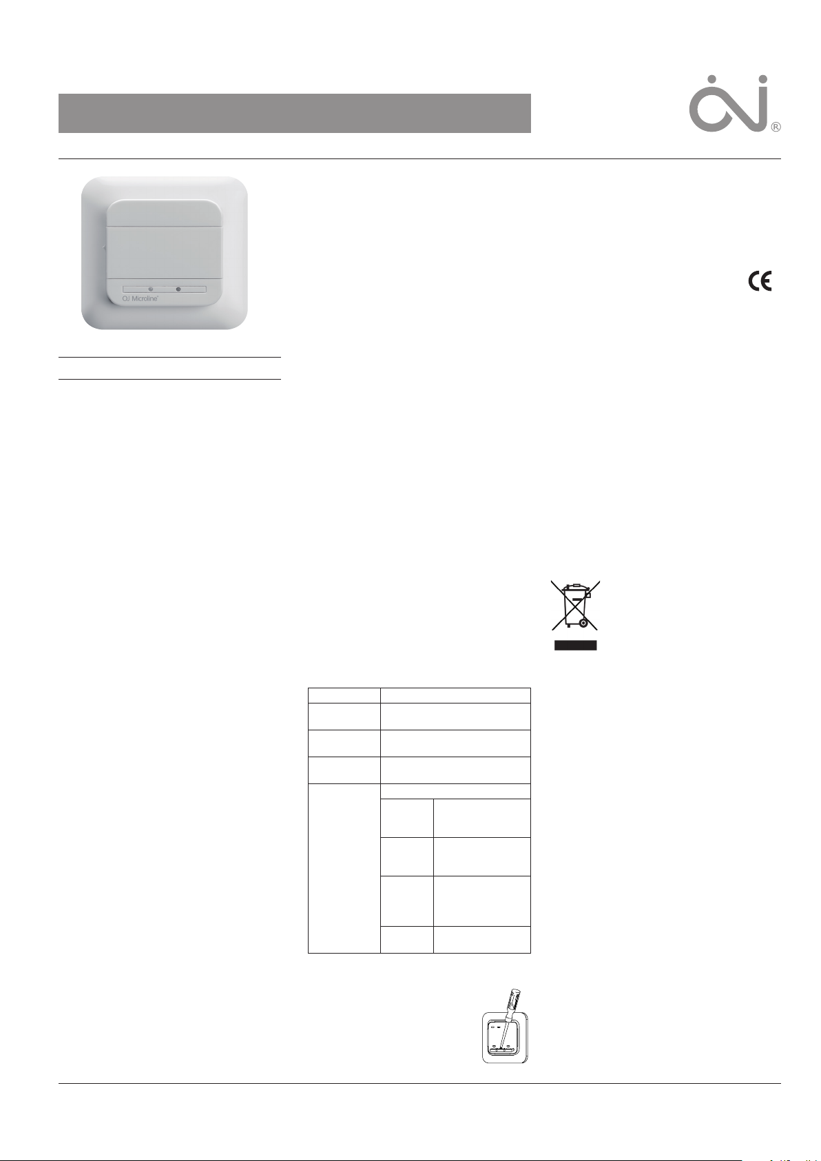
RELAY MODULE FOR CS4
Relay module for controlling electric heating
panels, etc., featuring night setback, frost protection and floor sensing thermostat mode.
Only for use in combination with the Central
Controller for wireless communication.
PRODUCT PROGRAMME
OSA4-10 Relay module incl. mount-
OSC4/MCS4-10 Central Controller incl.
floor sensor
WARNING – Important Safety Instructions
Disconnect the power supply before carrying
out any installation or maintenance work on this
unit and associated components. This unit and
associated components should only be installed
by a competent person (i.e. a qualified electrician). Electrical installation must be in accordance with appropriate statutory regulations
INSTALLING THE RELAY MODULE
The Relay module is designed for flush mounting in a wall socket or in the accompanying
mounting box.
Fig. 1:
1. Slide the power button down to O “0”.
2. Release the front cover ONLY by inserting a
small screwdriver into the hole on either side
of the Relay module.
Fig. 2, 2a eller 2b:
3. Connect the wires in accordance with the
diagram.
4. Mount the unit in a wall socket or the accompanying mounting box.
5. Fit the frame and carefully press the cover
onto the Relay module. Ensure that both
the power slide button on the cover and the
power switch pin are down.
DO NOT open the Relay module by releasing
the four fixing clips on the back.
APPLICATION
The relay module can be used for three dierent
control types: Night setback, Frost protection or
with an external floor sensor.
Fig. 2: Night setback
Connect the heating panel to terminal 4. The
relay module sets the heating panel in setback
mode according to the time programmed in the
4-event time schedule from the Central Controller (most heating panels have a built-in ”night
setback input-connector”).
Fig. 2a: Frost protection
Short-circuit terminals 5 and 6 to set the relay
TM
ing box
module to frost protection.
The relay module enters frost protection mode
and uses the built-in room sensor to maintain
the frost protection temperature.
In frost protection mode, the relay module
ensures that the heating panel maintains the
setpoint set on the Central Controller.
Fig. 2b: Thermostat with external sensor
Connect a floor sensor to terminals 5 and 6.
Now the relay module works as a thermostat
controlling the heating according the floor
temperature.
The relay module controls the temperature according to the 4-event time schedule from the
Central Controller.
MOUNTING THE RELAY MODULE
The accompanying mounting box makes it
easy to mount the Relay module on the wall.
Draughts and direct sunlight or other heat
sources must be avoided.
Fig. 3:
Observe the minimum distance of 0,5m, from
large metal surfaces, electronic equipment,
electric motors, etc.
Fig. 3a:
To ensure good signal transmission the unit
should be mounted as high as possible.
The unit should be mounted min. 0,5m above
the floor, away from the heating source, in such
a way that the unit is unaected by the floor
heat.
Fig. 3b:
To ensure good wireless transmission without
interference, all wireless units in the Comfort
System CS4
min. 1,0m between them.
SETTINGS
See user manual for CS4
and how to plan you system.
LED READOUTS
Green ON: Power ON, Relay module OK.
Green flashes
quickly:
Green flashes
slowly:
Red ON: Relay ON, power to heating
Red flashes
quickly:
FACTORY RESET
Allows factory settings to be restored and cancels the connection
to the Central Controller.
1. Remove the cover by inserting
2. Now hold the screwdriver on
TM
should always be placed with
TM
for further options
Connection sequence in
progress
No connection to Central
Controller
source
Error code
1 flash E1: Internal sensor
2 flashes E2: External sensor
5 flashes E5: Internal
6 flashes E6: Communica-
a small screwdriver into the hole
on one side of the thermostat.
defective or
short-circuited.
defective or
short-circuited
overheating.
Inspect the
installation.
tion error
the contact points under the LEDs.
Hold it until both LEDs flash three times. The
relay module has now been reset.
3. Mount the cover and turn the power o and
on again. The relay module will now connect
to the Central Controller.
CERTIFICATION
OJ Electronics A/S hereby declares that
the product conforms with the following
Directives of the European Parliament and
of the Council:
LVD, EMC, R&TTE, RoHS and WEEE
Applied standards
Please see the document “EC DECLARATION OF
CONFORMITY” in the back.
CLASSIFICATION
The product is a Class II device (enhanced insulation) and must be connected in the following
way:
Term. 1: Neutral (N)
Term. 2: Phase (L) 230 V ±10 %, 50/60 Hz
Term. 3-4: Load, max. 16 A / 3600 W
Term. X: Do not connect
Term. 5-6: Night setback, frost protection or
external floor sensor
ENVIRONMENT AND RECYCLING
Please help us to protect the environment by
disposing of the packaging in accordance with
national regulations for waste processing.
RECYCLING OF OBSOLETE APPLIANCES
Appliances with this label must not be
disposed of with general household
waste. They must be collected
separately and disposed of in
compliance with local regulations.
TECHNICAL DATA
Voltage .......................... 230 V AC ±10 % 50 Hz
Max. pre-fuse .............................................. 16 A
Built-in circuit breaker .................... 2-pole, 16 A
Output relay ............ Make contact - SPST - NO
Output ............................... Max. 16 A / 3600 W
Control principle ................................... PWM/PI
Stand-by power ........................................... 1 W
RF frequency band ...............................868 MHz
RF transmission range ..... 100 metres/open field
Frost protection ..................................+5/+10 °C
Ambient operating temperature ..........+0/+25 °C
Pollution degree ............................................... 2
Overvoltage ...............................................Cat. II
Rated impulse voltage ................................ 4 kV
Enclosure rating ........................................ IP 21*
Dimensions ..................... H/81, W/81, D/40 mm
Mounting depth ...................................... 20 mm
EU Registered Design ........ 001101349-0001/2
Automatic action type 1
* IP 21 applies only to front with cover after
mounting in a flush box
The relay module is maintenance free.
OJ ELECTRONICS A/S
Stenager 13B · DK-6400 Sønderborg
Tel: +45 73 12 13 14 · Fax: +45 73 12 13 13
oj@ojelectronics.com · www.ojelectronics.com
© 2016 OJ Electronics A/S
1
Page 2

Fig. 1
Min. 1m
Fig. 2
Fig. 2a
Fig. 2b
BR0987B08a
Fig. 3 Fig. 3a
BR0987B21a
BR0987B18a
BR0986B02a
BR0987B07a
BR0986B05a
Fig. 3b
BR986C01
2
Varemerket er et registrert varemerke tilhørende OJ Electronics A/S · © 2016 OJ Electronics A/S
 Loading...