

Page 1
Type ICD3-1999
USER MANUAL - ENGLISH
Contents
1
. Introduction . . . . . . . . . . . . . . . . . . . . . . . 1
2. Getting started . . . . . . . . . . . . . . . . . . . . . . . 1
3
. General Display . . . . . . . . . . . . . . . . . . . . . . . 1
4
. LED . . . . . . . . . . . . . . . . . . . . . . . 2
5. Buttons . . . . . . . . . . . . . . . . . . . . . . . 2
6
. Menus for Setting Up the Thermostat . . . . . . . . . . . . . . . . . 2
6.1. Operation . . . . . . . . . . . . . . . . . . . . . . . 2
6
.1.1. Auto . . . . . . . . . . . . . . . . . . . . . . 2
6.1.2. Manual . . . . . . . . . . . . . . . . . . . . . 2
6
.1.3. Comfort . . . . . . . . . . . . . . . . . . . . . 2
6
.2. Setting 4-event . . . . . . . . . . . . . . . . . . . . . 2
6.2.1. Example of Scheduling 4-event Set-up . . . . . . . . . . . . . 2
6
.3. Programming . . . . . . . . . . . . . . . . . . . . . . 2
6.4. General Settings . . . . . . . . . . . . . . . . . . . . . 2
6
.4.1. Language . . . . . . . . . . . . . . . . . . . . . 2
6.4.2. Time . . . . . . . . . . . . . . . . . . . . . . 2
6
.4.3. Day . . . . . . . . . . . . . . . . . . . . . . 3
6.4.4. Temperature . . . . . . . . . . . . . . . . . . . . 3
6.4.5. Child lock . . . . . . . . . . . . . . . . . . . . . 3
6
.4.6. Heater . . . . . . . . . . . . . . . . . . . . . . 3
6.4.7. Covering . . . . . . . . . . . . . . . . . . . . . 3
6
.4.8. Sub Floor . . . . . . . . . . . . . . . . . . . . . 3
6
.4.9. Application . . . . . . . . . . . . . . . . . . . . 3
6.4.10 Energy monitoring . . . . . . . . . . . . . . . . . . . 3
6
.5. Service . . . . . . . . . . . . . . . . . . . . . . . 3
6.6. Contact Details . . . . . . . . . . . . . . . . . . . . . 3
6.7. Engineer Settings . . . . . . . . . . . . . . . . . . . . . 3
6
.7.1. Readout . . . . . . . . . . . . . . . . . . . . . 3
6.7.2. Temp. Settings . . . . . . . . . . . . . . . . . . . 3
6.7.3. Adaptive function . . . . . . . . . . . . . . . . . . . 3
6.7.4. Offset . . . . . . . . . . . . . . . . . . . . . . 4
6.7.6. Reset . . . . . . . . . . . . . . . . . . . . . . 4
7. Error Messages . . . . . . . . . . . . . . . . . . . . . . . 4
8. Factory settings . . . . . . . . . . . . . . . . . . . . . . . 4
9. Appendix . . . . . . . . . . . . . . . . . . . . . . . 4
9.1. Table of Compatibility. . . . . . . . . . . . . . . . . . . . 4
9.2. Heat Definitions . . . . . . . . . . . . . . . . . . . . . 4
1
6
7069 06/11 (MBC)
1. Introduction
The ICD3 thermostat can switch on your
heating system at pre-determined times on
different days of the week. It is possible to set 4
periods called events each day with different
temperatures. The thermostat comes with a
default schedule that is suitable for most
installations. Unless you change these settings,
the thermostat will operate to this default
program.
Working with lower temperatures during times
that the room is unoccupied will lower your
energy costs without reducing the comfort. The
thermostat has an adaptive function that
automatically changes the start time of a
heating period so that the desired temperature
is reached at the time that you set. After 3 days
the adaptive function has learned when the
heating must be switched on.
2. Getting started
Quick set-up:
The first time you connect the power or after a
reset, the display will show you “Welcome to
Warmup”.
Push ENTER button. Then you can select:
• Language
• Time
• Day
• Temperature
• Child lock
• Heater?
• Covering?
• Sub floor
• Application
• Energy monitoring
Use the navigation buttons for selecting /
changing in the menus.
Important:
You have, as minimum, to select “Heater” and
“covering” to define the type of heater and
covering, before you can start up the
thermostat.
For further information, see point:
5. Buttons.
6.4. General settings.
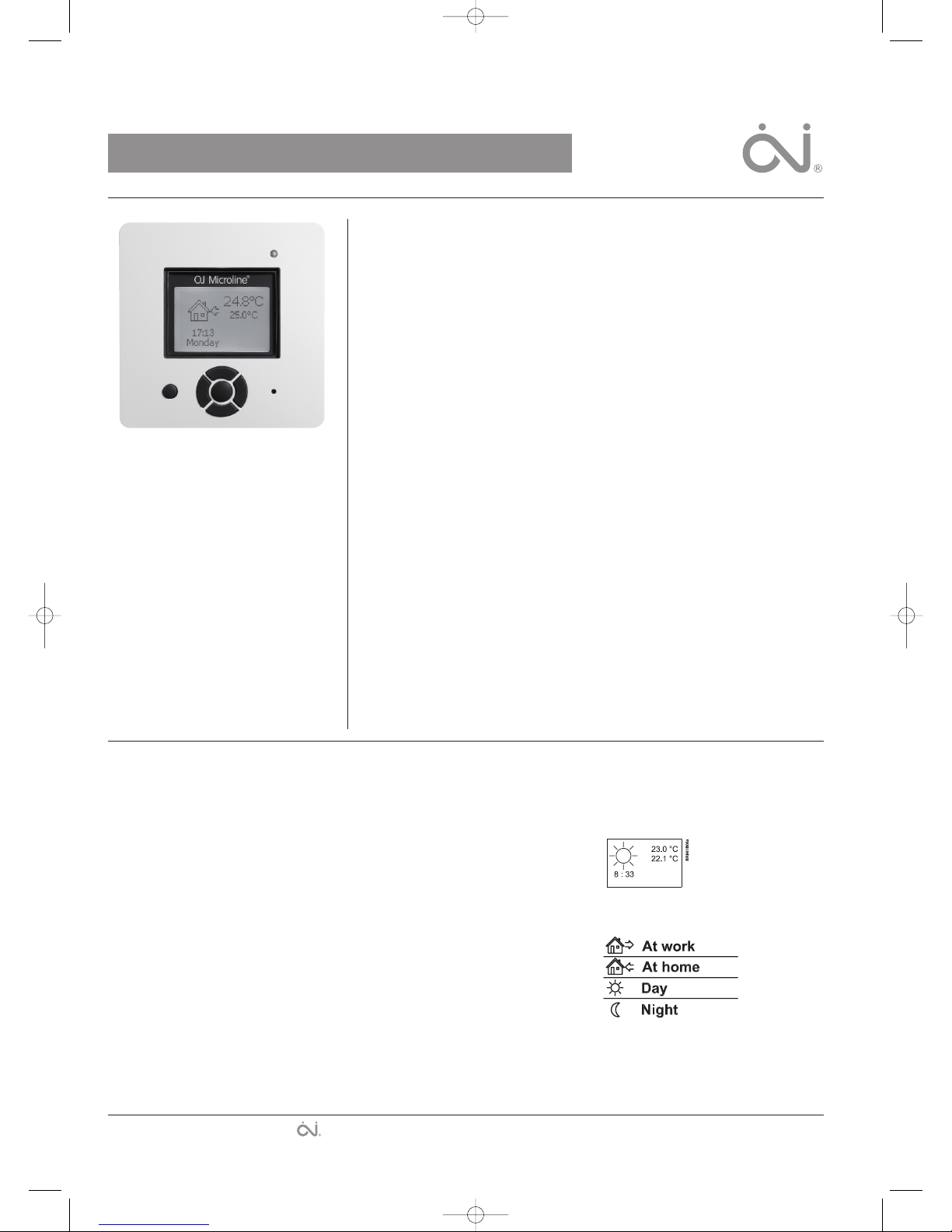
3. General Display
The display will normally
show the period (day, night,
home, out), the current
temperature, and the time.
The period is indicated by a symbol. Below you
can see a list of some of the symbols:
L
anguage
E
nglish . . . . . . Page 1 - 4
E
spañol
.
. . . . . Page 5 - 8
Deutsch . . . . . . Page 9 - 12
The trademark is registered and belongs to OJ Electronics A/S · © 2011 OJ Electronics A/S
67069-06-11.qxd:skabelon-A4 29/06/11 9:13 Side 1
Page 2
4
. LED
T
he LED is placed in the top right corner above
the display.
LED signal Indicates
C
onstant red light Relay is active
B
links System failure. (see error
m
essages)
No light Relay not active or
t
hermostat turned off
5. Buttons
Y
ou can use the standby button to turn display
a
nd regulation of temperature on/off. When the
thermostat is switched off, the relay
disengages. The clock will keep going, though.
W
hen you press the Reset button (use pen to
activate) for 3 seconds, a "Confirm factory
r
eset" text will be shown on the display. Then
press the ENTER button to reset the thermostat,
which will then start up with default values and
display the installation menu.
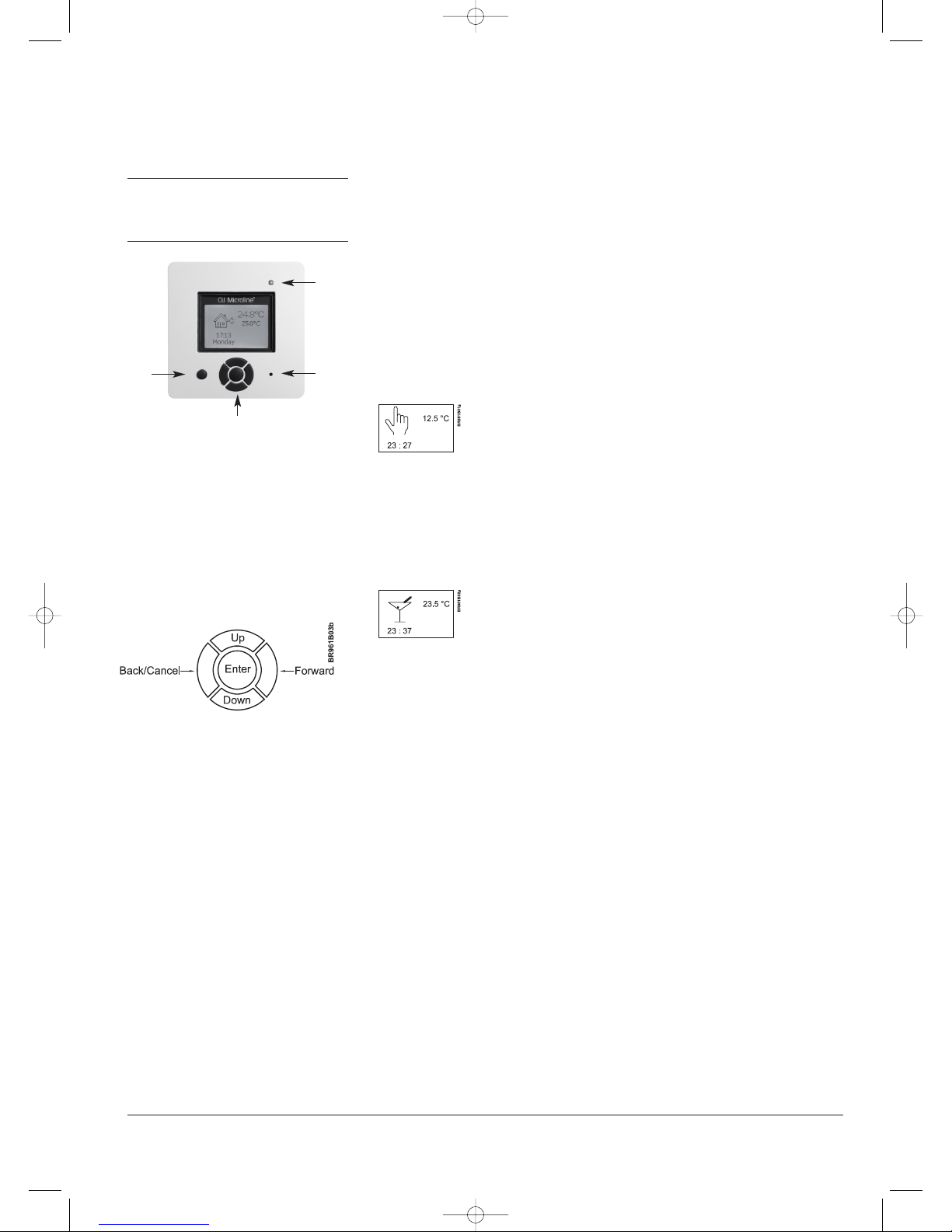
Thebuttons for navigating inthemenus and
selecting/changing settingsareplaced inthemiddle.
Back/Cancel • Go back in the menus (i.e.
upwards in the menu
hierarchy).
• Cancel changes of current
value.
Forward • Move forward in the menus
(i.e. downwards in the
menu hierarchy).
• Quick steps upwards when
specifying values, e.g.
temperature.
Up • Move up in menu.
• Raise current value, e.g.
temperature.
Down • Move down in menu.
• Lower current value, e.g.
temperature.
ENTER/Change • Select item from menu to
see/change/set value.
• Accept new/changed
setting.
6. Menus for Setting Up
the Thermostat
You can program the thermostat and make
various settings by using the menu system. To
open the main menu, press the ENTER button.
In the sections below every item on the main
menu will be described in more detail.
6.1. Operation
H
ere you can choose between three different
w
ays of setting the temperature(s):
6
.1.1. Auto
S
elect Auto if you want the temperature to be
c
ontrolled and operated automatically via the 4-
event system.
6
.1.2. Manual
Here you can cancel the scheduled 4-event
program (e.g. during holidays) and set the
w
anted temperature manually. You may want to
a
djust the temperature to for example 5°C for
frost protection while you are away.
T
o set the temperature, do the following:
1
. Select Manual.
2. Use the up/down button to raise/lower the
t
emperature.
3
. Press the ENTER button to finish.
Please note: The temperature that you set
m
anually will be valid until you cancel the
m
anual mode again by selecting Auto.
6
.1.3. Comfort
Here you can set a temporary Comfort
temperature (so-called party mode) for a single
e
vent.
To set the temperature, do the following:
1
. Select Comfort.
2. Use the up/down button to raise/lower the
temperature.
3. Press the ENTER button to finish.
Please note: Comfort mode is a temporary,
manual setting that will be automatically
cancelled by the next event in the scheduled 4event system.
6.2. Setting 4-event
If Auto has been selected in the Operation
menu, the 4-event system can be set to
automatically control the temperature settings
for each day in a period of 7 days.
You can select the desired temperature for Day
and Night, for when you are Out and at Home,
and for the Weekend Day and Weekend Night.
Moreover, you can define when you want each
time period (Day, Night, Out, Home, Weekend
Day, and Weekend Night) to begin.
Please note: You need to use the Down button
to move to the end of the menu.
Finally you can specify temperatures and
periods (Day, Night, Out, Home) for each day of
the week. Mon-Sun, 4-events option should be
selected in the Programming menu (will be
shown as Programming: 7:0 on the display).
Please refer to section 6.3 about Programming.
6.2.1. Example of Scheduling 4-event Set-up
If you in the Programming menu have selected
Mon-Fri, Sat-Sun (shown as Programming: 5:2
on the display) you can set up the 4 periods
(called events) in the following way:
1. Choose Day.
• Specify when Day time begins.
Use the up/down button to mark the
wanted time.
Press the ENTER button to finish.
• Specify the wanted Day temperature.
U
se the up/down button to raise/lower the
t
emperature.
Press the ENTER button to finish.
2
. Choose Out.
•
Specify when Out time begins.
• Specify the wanted temperature when you
a
re out and away from home (Out temp).
3. Choose Home.
• Specify when Home time begins.
•
Specify the wanted temperature when you
a
re at home (Home temp).
4
. Choose Night.
•
Specify when Night time begins.
•
Specify the wanted Night temperature.
5
. Choose Weekend Day.
•
Specify when Day time begins on
weekends.
• Specify the wanted Day temperature on
w
eekends.
6. Choose Weekend Night.
• Specify when Night time begins on
w
eekends.
•
Specify the wanted Night temperature on
weekends.
6
.3. Programming
Here you can choose between various
p
rogramming options that are used in
c
onnection with scheduling the 4-event system:
•
Mon-Fri, Sat-Sun
Will be shown as 5:2 on the display. This
setting allows you to have 5 days with the
same 4-events, and 2 days with the same 2
events. The days 1-5 are controlled by the
settings for Day, Night, Out, Home and
day 6-7 is controlled by the settings for
Weekend Day and Weekend Night.
• Mon-Sat, Sun
Will be shown as 6:1 on the display. This
setting allows you to have 6 days with the
same 4-events, and 1 day with 2 events.
The days 1-6 are controlled by the settings
for Day, Night, Out, Home and day 7 is
controlled by the settings for Weekend Day
and Weekend Night.
• Mon-Sun, 4-events
Will be shown as 7:0 on the display. This
setting allows you to have 7 days with 4
different events (Day, Night, Out, Home).
The days 1-7 are controlled by individual
day settings (Monday – Sunday).
6.4. General Settings
6.4.1. Language
Here you can select the language you want to
be used on the display. You can choose
between the following languages:
• English
• German (Deutsch)
• French (Francais)
• Spanish (Espanol)
• Portuguese (Portogese)
6.4.2. Time
• Here you can select whether 12- or 24-hour
clock should be used.
• To set the time, select Set time. Then use
the up/down buttons to adjust the time, and
press the ENTER button to finish.
2
Standby
Navigation
LED
Reset
© 2011 OJ Electronics A/S
67069-06-11.qxd:skabelon-A4 29/06/11 9:13 Side 2
Page 3
6.4.3. Day
H
ere you can set the day of the week:
•
Monday
• Tuesday
•
Wednesday
•
Thursday
•
Friday
• Saturday
•
Sunday
Please note: You need to use the Down button
to move to the end of the list of weekdays.
6
.4.4. Temperature
Scale
H
ere you can specify what temperature unit
s
hould be used in the display:
•
°C (Celsius, with a resolution of 0.5 degree)
• °F (Fahrenheit, with a resolution of 1
d
egree)
•
A scale from 1-10 (in steps of about 10°).
Display shows
H
ere you can decide whether the display shall
s
how the time, set point and/or air/floor
temperature.
•
Time (On/Off)
•
Set point (On/Off) (The current temperature
that the thermostat has been set to, for
i
nstance in the 4-event settings.)
•
Air Temp. (On/Off). The air/floor
temperature currently registered by the
sensor.
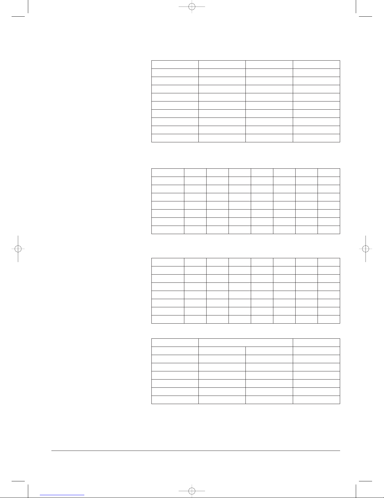
6.4.5. Child lock
By switching on the child lock you can lock the
menus (marked with a padlock symbol on the
display). Then it will no longer be possible to
select the sub-menus and change the settings.
You can still set a comfort temperature and the
time, though.
Please note: You can still use the Reset button
to return to factory settings, if the child lock has
been switched on.
6.4.6. Heater
Here you can define the type of heater that the
thermostat is attached to:
• Undertile
• Underlaminate
• Undercarpet
• Inscreed
• Type A
• Type B
• User Defined
Please refer to Appendix for configuration table
showing combinations of heater type and
covering.
6.4.7. Covering
Here you can enter the type of floor covering:
• Ceramic Tiles
• Stone
• Laminate
• Wood
• Carpet
• Vinyl
• Other
Please refer to Appendix for configuration table
showing combinations of heater type and
covering.
6.4.8. Sub Floor
H
ere you can enter the type of sub floor:
•
Concrete
• Screed
•
WBP Ply
•
Ins. Backer Board
•
Backer Board
6
.4.9. Application
H
ere you can select the type of regulator
application:
•
Floor Temp. Cont.: A floor sensor is used.
• Fl. Cont. 2 sensors: Both floor sensor and
l
imit sensor are used. A maximum
t
emperature limit can be set for the limit
s
ensor, so the thermostat will switch off if
the temperature at the place of the limit
s
ensor reaches the maximum temperature.
T
his set-up with a limit sensor can, for
instance, be used to avoid damage to some
delicate floor covering.
•
Air Temp. Control: The sensor is placed in
the thermostat.
•
Air Cont. Floor limit: Apart from the sensor
i
nside the thermostat an extra limit sensor
is used. A maximum temperature limit can
b
e set for the limit sensor, so the
t
hermostat will switch off if the temperature
at the position of the limit sensor reaches
the maximum temperature. This set-up with
a
n extra limit sensor can, for instance, be
u
sed to avoid damage to some delicate
floor covering.
• Regulator Control: No sensor is used here.
The thermostat will turn on in sequences of
20 minutes, and you can specify the length
of the sequences as a percentage of 20
minutes. If you, for example, set the
regulator to 50, the thermostat will turn on
for 10 minutes, switch off for 10 minutes,
and then turn on again for 10 minutes.
• External Control: Used in case of a set-up
with several thermostats being controlled
by an external master thermostat. Then the
thermostat will work as a slave, and you
cannot apply any settings at all since the
master thermostat controls it.
6.4.10. Energy monitoring
Here you can read-out the energy consumption
for the past:
• 2 Days
• 30 Days
• 360 Days
Press ENTER for the chosen period. The
value in percent (%) shows how much of
the time there has been heat. The following
calculates the cost for the selected period.
Ensure the price of heating is correct, if not,
check the settings for subsequent currency
price per kW/h and the load:
• Currency: Press ENTER and chose the
desired currency. Confirm with ENTER.
• Cost: Press ENTER and set the actual cost
of electricity. The cost must be inserted per
kW/h. Press ENTER.
• Load: Press ENTER and enter the
connected heating power. The value must
be in Watt (W). Press ENTER.
Leave the menu by Exit.
6.5. Service
If you need technical help then select Service
from the main menu to see the contact
information.
6.6. Contact Details
Select Contact Details from the main menu to
see the contact information.
OJ ELECTRONICS A/S
S
tenager 13B · DK-Sønderborg · Denmark
T
. +45 73 12 13 14 · F. +45 73 12 13 13
oj@ojelectronics.com · www.ojelectronics.com
6
.7. Engineer Settings
T
o select Engineer settings, press the up and
down button at the same time for 5 seconds.
N
ote: Changes may invalidate warranty.
6.7.1. Readout
Here you see readouts of the following current
t
emperatures:
•
Room temp
• Floor temp
•
Floor limit temp
Y
ou can also get readouts of some statistics:
• Min daily: A percentage indicating the
m
inimum activated period within 24 hours
o
ver the last 14 days.
• Max daily: A percentage indicating the
m
aximum activated period within 24 hours
o
ver the last 14 days.
• Min Air: Minimum room temperature within
t
he last 48 hours.
• Mean Air: Average room temperature within
t
he last 48 hours.
• Max Air: Maximum room temperature
within the last 48 hours.
•
Min Floor: Minimum floor temperature
within the last 48 hours.
• Mean Floor: Average floor temperature
within the last 48 hours.
• Max Floor: Maximum floor temperature
within the last 48 hours.
• Cut out cnt: Number of relay connections
in the service life of the thermostat. This
value is never reset.
• Application: Here you can get readout for
the current application type that has been
selected in the General settings
- Floor
- Floor-2
- Air
- Air-Limit
- Reg.
- Ext.
• Software ver.: Indicates the current version
of the software.
6.7.2. Temp. Settings
Here you can specify the wanted minimum and
maximum temperatures for air, floor, or external
limit sensor.
Before you can select minimum and maximum
limits for air, floor or limit sensor, the application
for the regulator type in question must be chosen.
Please refer to section 6.4.9 about General
Settings – Application for more details.
Please note: If you do not specify any settings
here, the factory settings will be used.
• Air Temp. Range
- Max Temp
- Min Temp
• Floor Temp. Range
- Max Temp
- Min Temp
• Limit Sensor
- Max Temp
- Min Temp
3
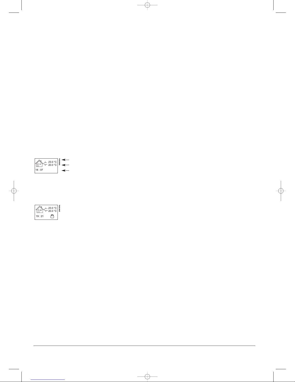
A
ir/floor temperature
Set point
T
ime
© 2011 OJ Electronics A/S
67069-06-11.qxd:skabelon-A4 29/06/11 9:13 Side 3
Page 4
6.7.3. Adaptive function
H
ere you can activate/deactivate (On/Off) the
a
daptive function. This function is only related
to the 4-event timer and only works in
c
onnection with going from one event to
a
nother where the temperature is going to be
r
aised. The adaptive function finds out when the
thermostat shall start heating to ensure that the
r
ight temperature is reached at the time that it
h
as been programmed for.
6.7.4. Offset
O
ffset is used to compensate for any difference
b
etween the thermostat and a room
thermometer. If the thermometer, for instance,
s
hows 1°C more than the thermostat, it is
p
ossible to adjust the offset by +/- 5°C. Then
t
he thermostat will show the same temperature
as the thermometer. If the thermostat for
e
xample shows 1 degree too much, offset
s
hould be set to +1. Then the temperature will
be set 1 degree lower.
O
ffset applies to both built-in and external
s
ensors whereas the limit sensor, if any, is not
affected.
6
.7.6. Reset
•
Reset 2: Reset values defined in Engineer
settings to factory settings.
•
Reset 3: Equal to Reset 2, except history
data are deleted. The number of relay
connections is not deleted, though.
7. Error Messages
I
f you get an error the LED is flashing red.
Internal failure The thermostat is defective,
replace thermostat
External failure External sensor or heating
unit is defective.
4
D
ay 1-5
Event
Time With floor sensor With air sensor
Day 06:00-08:00 25°C 20°C
Out 08:00-16:00 20°C 15°C
H
ome
1
6:00-22:30
2
5°C
2
2°C
Night 22:30-06:00 20°C 15°C
Day 6-7
Event Time With floor sensor With air sensor
D
ay
0
8:00-23:00
2
5°C
2
2°C
N
ight
2
3:00-08:00
2
0°C
1
5°C
8
. Factory settings
T
he thermostat is delivered with factory set programs as follows:
Tiles Stone Laminate Wood Carpet Vinyl Other
U
ndertile
Y
ES
Y
ES
N
O
N
O
N
O
N
O
Y
ES
Underlaminate NO NO YES YES NO NO YES
U
ndercarpet
N
O
N
O
Y
ES
Y
ES
Y
ES
Y
ES
Y
ES
I
nscreed
Y
ES
Y
ES
Y
ES
Y
ES
Y
ES
Y
ES
Y
ES
Type A YES YES NO NO NO NO YES
Type B NO NO NO NO YES YES YES
U
ser Defined
Y
ES
Y
ES
Y
ES
Y
ES
Y
ES
Y
ES
Y
ES
Tiles Stone Laminate Wood Carpet Vinyl Other
Undertile A A n/a n/a n/a n/a E
Underlaminate n/a n/a B B n/a n/a E
Undercarpet n/a n/a B B C C E
Inscreed A A B B C C E
Type A D D n/a n/a n/a n/a E
Type B n/a n/a n/a n/a C C E
User Defined E E E E E E E
Configuration Control temperature Overheat
Room Floor
Min. Max.
Min. Max. Max.
A 5 30 5 40 40
B 5 27 5 27 27
C 5 25 5 25 27
D 5 30 5 50 55
E prog prog prog
9
. Appendix
9.1. Table of Compatibility
9.2. Heat Definitions
n/a = not available
© 2011 OJ Electronics A/S
67069-06-11.qxd:skabelon-A4 29/06/11 9:13 Side 4
Page 5

Type ICD3-1999
MANUAL PARA EL USUARIO - ESPAÑOL
Contenido
1. Introducción . . . . . . . . . . . . . . . . . . . . . . . 5
2
. Instrucciones iniciales . . . . . . . . . . . . . . . . . . . . . 5
3. Pantalla general . . . . . . . . . . . . . . . . . . . . . . . 5
4
. LED . . . . . . . . . . . . . . . . . . . . . . . 6
5. Botones . . . . . . . . . . . . . . . . . . . . . . . 6
6
. Menús para ajustar el termostato. . . . . . . . . . . . . . . . . . . 6
6
.1. Funcionamiento . . . . . . . . . . . . . . . . . . . . . 6
6.1.1. Auto . . . . . . . . . . . . . . . . . . . . . . 6
6
.1.2. Manual . . . . . . . . . . . . . . . . . . . . . 6
6.1.3. Confort . . . . . . . . . . . . . . . . . . . . . 6
6
.2. Ajuste de 4 eventos . . . . . . . . . . . . . . . . . . . . 6
6.2.1. Ejemplo de programación del Ajuste de 4 eventos . . . . . . . . . . 6
6
.3. Programación . . . . . . . . . . . . . . . . . . . . . . 6
6.4. Ajustes generales . . . . . . . . . . . . . . . . . . . . . 6
6.4.1. Idioma . . . . . . . . . . . . . . . . . . . . . . 6
6
.4.2. Hora . . . . . . . . . . . . . . . . . . . . . . 7
6.4.3. Día. . . . . . . . . . . . . . . . . . . . . . . 7
6
.4.4. Temperatura . . . . . . . . . . . . . . . . . . . . 7
6.4.5. Bloqueo para niños (Bloq. p. niños) . . . . . . . . . . . . . . 7
6
.4.6. Calefactor (Calefact.) . . . . . . . . . . . . . . . . . . 7
6.4.7. Cubierta (Cbrta.) . . . . . . . . . . . . . . . . . . . 7
6.4.8. Contrapiso (Cntr.piso). . . . . . . . . . . . . . . . . . 7
6
.4.9. Aplicación . . . . . . . . . . . . . . . . . . . . . 7
6.4.10. Monitoreo de energía . . . . . . . . . . . . . . . . . . 7
6
.5. Servicio . . . . . . . . . . . . . . . . . . . . . . . 7
6.6. Información de contactos. . . . . . . . . . . . . . . . . . . 7
6
.7. Ajustes ingeniería . . . . . . . . . . . . . . . . . . . . . 7
6.7.1. Lectura . . . . . . . . . . . . . . . . . . . . . 7
6.7.2. Ajustes de la temp. . . . . . . . . . . . . . . . . . . 7
6.7.3. Función adaptativa (Func. adapt.) . . . . . . . . . . . . . . . 7
6.7.4. Compensación (Compens.) . . . . . . . . . . . . . . . . 8
6.7.6. Reajuste . . . . . . . . . . . . . . . . . . . . . 8
7. Mensajes de error. . . . . . . . . . . . . . . . . . . . . . . 8
8. Ajustes de fábrica. . . . . . . . . . . . . . . . . . . . . . . 8
9. Anexo . . . . . . . . . . . . . . . . . . . . . . . 8
9.1. Tabla de compatibilidad . . . . . . . . . . . . . . . . . . . 8
9.2. Definiciones de calefacción . . . . . . . . . . . . . . . . . . 8
5
1. Introducción
El termostato ICD3 es capaz de activar su sistema de calefacción a horas predeterminadas
en días diferentes de la semana. Es posible
establecer 4 períodos llamados eventos cada
día con diferentes temperaturas. El termostato
viene con un programa predeterminado que es
adecuado para la mayoría de las instalaciones.
A menos que usted cambie estos ajustes, el
termostato funcionará con este programa predeterminado.
El funcionamiento con temperaturas menores
durante las horas en que la habitación no esté
habitada reducirá sus costes de energía sin
sacrificar su comodidad. El termostato tiene
una función adaptativa que cambia automáticamente la hora de activación de un período de
calefacción de manera que se alcance la temperatura deseada a la hora que usted lo establezca. Después de 3 días, la función adaptativa habrá aprendido a qué hora deberá activarse la calefacción.
2. Instrucciones iniciales
Instalación rápida: La primera vez que usted
conecte la alimentación eléctrica o después de
un reajuste, la pantalla mostrará el mensaje
“Bienvenido a Warmup”.
Pulse el botón Aceptar. Después puede seleccionar:
• Idioma
• Hora
• Día
• Temperatura
• Bloqueo para niños (Bloq. p. niños)
• Calefactor (Calefact.)
• Cubierta (Cbrta.)
• Contrapiso (Cntr.piso)
• Aplicación
• Monitoreo de energía (Mon. de energía)
Use los botones de navegación para seleccionar o cambiar los menús.
¡Importante!
Usted tiene que seleccionar, como mínimo,
“Calefact.” y “Cbrta.” para definir el tipo de
calefactor y cubierta antes de poder activar el
termostato. Si desea obtener más información,
sírvase ver el punto:
5. Botones.
6.4. Ajustes generales.
3. Pantalla general
Normalmente, la pantalla
mostrará el período (día,
noche, en casa, ausente),
la temperatura actual, y la
hora.
El período se indica por medio de un símbolo.
A continuación se muestra un listado de algunos de los símbolos:
Ausente
En casa
Día
Noche
B
La marca es una marca comercial registrada de OJ Electronics A/S · © 2011 OJ Electronics A/S
67069-06-11.qxd:skabelon-A4 29/06/11 9:13 Side 5
Page 6

4
. LED
E
l indicador LED está ubicado en la esquina
superior derecha encima de la pantalla.
Señal LED Indica
L
uz roja continua El relé está activo
C
entellea Falla del sistema. (ver
(
ver mensajes de error)
No se ilumina El relé no está activo o se
a
pagó el termostato.
5. Botones
Se puede usar el botón de listo y en espera
p
ara encender y apagar la pantalla y regular la
t
emperatura. Cuando se desactiva el termostato, se desactiva el relé. Sin embargo, el reloj
continuará funcionando.
A
l pulsar el botón de reajuste (use una pluma
para activarlo) durante 3 segundos, en la pantal
la aparecerá el mensaje "Confirmar reajuste de
fábrica". Después pulse el botón Aceptar para
reajustar el termostato, el cual comenzará
entonces con los valores predeterminados y
mostrará el menú de instalación.
Los botones para navegar a través de los
menús y para seleccionar y cambiar los ajustes
están colocados en la parte media.
Volver/Cancelar • Retroceder en los menús
(por ejemplo, hacia arriba
en la jerarquía de menú).
• Anular los cambios del
valor actual.
Adelante • Avanzar en los menús (por
ejemplo, hacia abajo en la
jerarquía de menú).
• Avanza rápidamente hacia
arriba al especificar los
valores, por ejemplo, la
temperatura.
Arriba • Ascender en el menú.
• Elevar el valor actual, por
ejemplo, la temperatura.
Abajo • Descender en el menú.
• Reducir el valor actual, por
ejemplo, la temperatura.
Aceptar/Cambiar • Seleccionar el elemento de
menú para ver / cambiar /
establecer el valor.
• Aceptar ajuste
nuevo/modificado.
6. Menús para ajustar el termostato
Usted puede programar el termostato y efectuar varios ajustes utilizando el sistema de
menú. Para abrir el menú principal, pulse el
botón Aceptar. En las secciones a continuación
cada elemento en el menú principal se describ
irá en mayor detalle.
6.1. Funcionamiento
A
quí, usted puede seleccionar entre tres mane-
r
as diferentes de ajustar las temperatura(s):
6.1.1. Auto
S
eleccione Auto si desea controlar y operar
a
utomáticamente la temperatura a través del
sistema de 4 eventos.
6
.1.2. Manual
A
quí usted puede cancelar el programa de 4
eventos (por ejemplo, durante las vacaciones) y
e
stablecer manualmente la temperatura. Quizá
d
esee ajustar la temperatura a, por ejemplo, 5°
C
para protección contra el congelamiento
mientras se encuentra fuera de casa.
P
ara ajustar la temperatura, haga lo siguiente:
1. Seleccione Manual.
2. Use el botón arriba/abajo para subir/bajar la
t
emperatura.
3
. Pulse el botón Aceptar para terminar.
Tome nota: La temperatura que establezca
m
anualmente será válida hasta que vuelva a
a
nular el modo manual mediante la selección
del modo Auto.
6.1.3. Confort
A
quí puede ajustar una temperatura temporal
Confort (conocida también como modalidad
de fiesta) para un solo evento.
Para ajustar la temperatura, haga lo siguiente:
1. Seleccione Confort.
2. Use el botón arriba/abajo para subir/bajar la
temperatura.
3. Pulse el botón Aceptar para terminar.
Tome nota: La modalidad Confort es un ajuste
manual y temporal que se anulará automáticamente cuando comience el siguiente evento
programado en el sistema de 4 eventos.
6.2. Ajuste de 4 eventos
Si se ha seleccionado Auto en el menú de
Operación, se podrá ajustar el sistema de 4
eventos para controlar automáticamente los
ajustes de temperatura para cada día en un
período de 7 días.
Puede seleccionar la temperatura deseada para
el Día y la Noche, para cuando usted esté
Ausente y En casa, y también para Fin de
semana Día y Fin de semana Noche.
Además, usted puede definir cuándo desea
que comience cada período de tiempo (Día,
Noche, Ausente, En casa, Fin de semana
Día, y Fin de semana Noche).
Tome nota: Es necesario que utilice el botón
Abajo para llegar hasta el final del menú.
Finalmente, usted puede especificar temperaturas y períodos (Día, Noche, Ausente, En casa)
para cada día de la semana (Lunes, Martes,
Miércoles, Jueves, Viernes, Sábado y
Domingo). Sin embargo, esto requiere que se
seleccione la opción Lun-Dom, 4 eventos en
el menú de Programación (se mostrará como
Programación: 7:0 en la pantalla). Le sugerimos consultar la sección 6.3 pertinente a
Programación.
6.2.1. Ejemplo de programación del Ajuste
d
e 4 eventos
S
i en el menú Programación ha seleccionado
L
un-Vie
, Sáb-Dom (que aparece como
P
rogramación: 5:2 en la pantalla) podrá ajustar
l
os 4 períodos (llamados eventos) de la manera
s
iguiente:
1
. Seleccione Día.
•
Especificar cuándo comienza Hora del día.
Use el botón arriba/abajo para marcar la
hora deseada.
P
ulse el botón Aceptar para terminar.
•
Especifique la Temperatura de día (Temp.
de día) deseada.
U
se el botón arriba/abajo para subir/bajar
l
a temperatura.
P
ulse el botón Aceptar para terminar.
2. Seleccione Ausente.
•
Especifique cuándo comienza Hora de
a
usencia (Hora de aus.).
• Especifique la temperatura deseada cuando esté ausente y lejos de casa (Temp. de
a
us.).
3
. Seleccione En casa.
• Especifique cuándo comienza Hora en casa.
• Especifique la temperatura deseada cuand
o esté en casa (Temp. casa).
4
. Seleccione Noche.
• Especifique cuándo comienza Hora noc-
t
urna.
•
Especifique la Temperatura nocturna
(Temp. noct.) deseada.
5. Seleccione Fin de semana Día
(
Fin de sem. Día).
•
Especifique cuándo comienza Hora del día
durante los fines de semana.
•
Especifique la Temperatura de día (Temp.
de día) deseada durante los fines de semana.
6. Seleccione Fin de semana Noche (Fin de
sem. Noche).
• Especifique cuándo comienza Hora noc-
turna (Hora noct.) durante los fines de
semana.
• Especifique la Temperatura nocturna
(Temp. noct.) deseada durante los fines de
semana.
6.3. Programación
Aquí usted puede seleccionar entre diversas
opciones de programación que se utilizan en
conexión con la programación del sistema de 4
eventos:
• Lun-Vie, Sáb-Dom
En la pantalla aparecerá como 5:2. Este
ajuste le permite tener 5 días con los mismos 4 eventos, y 2 días con los mismos 2
eventos. Los días 1-5 se controlan por
medio de los ajustes para Día, Noche,
Ausente, En casa y los días 6-7 se controla
por medio de los ajustes para Fin de sem.
Día y Fin de sem. Noche.
• Lun-Sáb, Dom
En la pantalla aparecerá como 6:1. Este
ajuste le permite tener 6 días con los mismos 4 eventos, y 1 día con 2 eventos. Los
días 1-6 se controlan por medio de los
ajustes para Día, Noche, Ausente, En casa
y el día 7 se controla por medio de los
ajustes para Fin de sem. Día y Fin de sem.
Noche.
• Lun-Dom, 4 eventos
En la pantalla aparecerá como 7:0. Este
ajuste le permite tener 7 días con 4 eventos
diferentes (Día, Noche, Ausente, En casa).
Los días 1-7 se controlan mediante ajustes
individuales del día (lunes – domingo).
6.4. Ajustes generales
6.4.1. Idioma
Aquí, usted puede seleccionar el idioma que
desee utilizar en la pantalla. Puede elegir entre
los siguientes idiomas:
6
Listo y en
espera
Navegación
LED
Volver/
Cancelar
Adelante
Enter
Arriba
Abajo
BR961B03a-E
Reajuste
© 2011 OJ Electronics A/S
67069-06-11.qxd:skabelon-A4 29/06/11 9:13 Side 6
Page 7

• Inglés (English)
•
Alemán (Deutsch)
•
Francés (Francais)
• Español
•
Portugués (Português)
6
.4.2. Hora
• Aquí usted puede seleccionar el formato de
h
orario que desea utilizar, de 12 horas o de
2
4 horas.
• Además, desde aquí puede ajustar la hora.
Para ajustar la hora, seleccione Hora
a
juste. Entonces use los botones arriba
/
abajo para ajustar la hora, y pulse el botón
Aceptar para terminar.
6
.4.3. Día
A
quí puede ajustar el día de la semana:
• Lunes
•
Martes
•
Miércoles
• Jueves
• Viernes
•
Sábado
•
Domingo
Tome nota: Es necesario que utilice el botón
Abajo para llegar hasta el final de la lista de los
d
ías de la semana.
6.4.4. Temperatura
E
scala
A
quí, puede especificar qué unidades de tem-
peratura se utilizarán en la pantalla:
• °C (Celsius, con una resolución de
0
,5 grados)
•
°F (Fahrenheit, con una resolución
de 1 grado)
•
Una escala de 1 a 10 (en pasos de
aproximadamente 10°).
La pantalla muestra
Aquí, puede decidir si desea que la pantalla
muestre la hora, el punto de ajuste y/o la temperatura del aire/piso.
• Hora (Encendido/Apagado)
• Punto ajuste (Encendido/Apagado) (La
temperatura actual a la que el termostato
se ha ajustado, por ejemplo, en los ajustes
de 4 eventos).
• Temp. aire. (Encendido/Apagado). La temperatura del aire/piso actualmente detectada por el sensor.
6.4.5. Bloqueo para niños (Bloq. p. niños)
Al activar el bloqueo para niños puede bloquear
los menús (marcados con un símbolo de candado en la pantalla). Al hacerlo, ya no será
posible seleccionar los submenús ni cambiar
los ajustes. Sin embargo, aún se podrá ajustar
una temperatura de confort y la hora.
Tome nota: Se puede aún utilizar el botón de
Reajuste para volver a los ajustes de fábrica, si
se hubiese activado el bloqueo para niños.
6.4.6. Calefactor (Calefact.)
Aquí, puede definir el tipo de calefactor al cual
está acoplado el termostato:
• Bajo losetas
• Bajo laminados
• Bajo alfombra
• Hormigón
• Tipo A
• Tipo B
• Definido por el usuario
Consulte en el Anexo la tabla de configuración
q
ue muestra las combinaciones del tipo de
c
alefactor y la cubierta.
6
.4.7. Cubierta (Cbrta.)
A
quí puede introducir el tipo de cubierta de
p
iso:
• Baldosa Cerámica
•
Piedra
•
Laminado
• Madera
• Alfombra
•
Vinilo
•
Otro
Consulte en el Anexo la tabla de configuración
q
ue muestra las combinaciones del tipo de
c
alefactor y la cubierta.
6.4.8. Contrapiso (Cntr.piso)
A
quí puede introducir el tipo de contrapiso:
•
Hormigón
• Pavimento
• Madera contrachapada WBP (Mad. Cntr.
C
hap. WBP)
•
Placa de aislamiento IBB
• Placa de refuerzo
6
.4.9. Aplicación
A
quí puede seleccionar el tipo de aplicación de
regulador:
•
Control de la temperatura de piso (Cont.
t
emp. de piso): Se utiliza un sensor de piso.
• 2 sensores de control de piso (2 sensores
de Cont. de piso): Se utilizan el sensor de
p
iso y el sensor limitador. Se puede esta-
b
lecer un límite máximo de temperatura
para el sensor limitador, de manera que el
t
ermostato se apagará si la temperatura en
la ubicación del sensor limitador alcanza el
valor máximo seleccionado. Esta configuración con un sensor limitador, puede utilizarse, por ejemplo, para evitar daños a
algunas cubiertas de piso delicadas.
• Control de la temperatura del aire (Cont.
temp. Aire): El sensor se coloca en el termostato.
• Control de la temperatura del aire límite
con sensor de piso (Lím. suelo cont. Aire):
Además del sensor dentro del termostato
se utiliza un sensor limitador adicional. Se
puede establecer un límite máximo de temperatura para el sensor limitador, de manera que el termostato se apagará si la temperatura en la ubicación del sensor limitador alcanza el valor máximo seleccionado.
Esta configuración con un sensor limitador
adicional, se puede utilizar, por ejemplo,
para evitar daños a algunas cubiertas de
piso delicadas.
• Control regulador (Contr. regulador): Aquí
no se utiliza ningún sensor. El termostato
se activará en secuencias de 20 minutos, y
usted puede especificar la duración de las
secuencias como un porcentaje de 20
minutos. Por ejemplo, si usted ajusta el
regulador a 50, el termostato se encenderá
durante 10 minutos, se apagará durante 10
minutos, y después se volverá a encender
10 minutos.
•
Control externo (Contr. ext.): Se usa en el
caso de una configuración con varios termostatos que se controlan desde un termostato maestro externo. Entonces el termostato
funcionará como esclavo, y no podrá aplicar
ajuste alguno en absoluto dado que el termostato maestro los controla.
6.4.10. Monitoreo de energía
Desde aquí puede leer el consumo de energía
durante los últimos:
• 2 días
• 30 días
• 360 días
Pulse ENTER para el período seleccionado.
El valor en porcentaje (%) muestra qué
tanto tiempo ha estado activa la calefacc
ión. Lo siguiente calcula el coste para el
p
eríodo seleccionado. Asegúrese de que el
precio de la calefacción sea el correcto, de
l
o contrario, verifique los ajustes para el
p
recio de divisa subsecuente por kW/h y la
c
arga:
• Divisa: Pulse ENTER y seleccione la divisa
d
eseada. Pulse ENTER para confirmar.
•
Coste: Pulse ENTER y ajuste el coste real
de la electricidad. Será necesario introducir
el coste por kW/h. Pulse ENTER.
•
Carga: Pulse ENTER e introduzca la potenc
ia de calefacción conectada. El valor debe
estar en vatios (W). Pulse ENTER.
P
ulse Exit para salir del menú.
6
.5. Servicio
Si necesita asistencia técnica entonces selecc
ione Servicio desde el menú principal para
v
isualizar la información de contactos.
6.6. Información de contactos
S
eleccione Info. Contactos del menú principal
p
ara ver la información de contactos.
OJ ELECTRONICS A/S
S
tenager 13B · DK-Sønderborg · Denmark
T
. +45 73 12 13 14 · F. +45 73 12 13 13
oj@ojelectronics.com · www.ojelectronics.com
6
.7. Ajustes ingeniería
Para seleccionar Ajustes ingeniería, pulse los
botones arriba y abajo simultáneamente durant
e 5 segundos.
N
ota: Cambios pueden anular la garantía.
6
.7.1. Lectura
Aquí usted ve las lecturas de las siguientes
temperaturas actuales:
• Temperatura ambiente (Temp. amb.)
• Temperatura del suelo (Temp. suelo)
• Temperatura límite del suelo (Temp. límite)
Además puede obtener lecturas de algunas
estadísticas:
• Mín. diario: Un porcentaje que indica el
período mínimo activado en un lapso de 24
horas durante los pasados 14 días.
• Máx. diario: Un porcentaje que indica el
período máximo activado en un lapso de
24 horas durante los pasados 14 días.
• Aire (mín.): Temperatura ambiente mínima
durante las 48 horas recién pasadas.
• Aire (medio): Temperatura ambiente promedio durante las 48 horas recién pasadas.
• Aire (máx.): Temperatura ambiente máxima
durante las 48 horas recién pasadas.
• Suelo (mín.): Temperatura mínima del
suelo durante las 48 horas recién pasadas.
• Suelo (medio): Temperatura promedio del
suelo durante las 48 horas recién pasadas.
• Suelo (máx.): Temperatura máxima del
suelo durante las 48 horas recién pasadas.
• Cont. corte: Número de conexiones de
relé en la vida útil de servicio del termostato. Este valor no se puede reajustar.
• Aplicación: Aquí puede obtener la lectura
para el tipo de aplicación actual que se ha
seleccionado en Ajustes generales
- Suelo
- Suelo-2
- Aire
- Aire-límite
- Reg. (Control regulador)
- Ext. (Control externo)
• Vers. software.: Indica la versión actual
del software.
6.7.2. Ajustes de la temp.
Aquí puede especificar las temperaturas mínimas y máximas deseadas para el aire, el suelo
o para el sensor limitador externo.
7
Temperatura del aire/piso
Punto de ajuste
Hora
© 2011 OJ Electronics A/S
67069-06-11.qxd:skabelon-A4 29/06/11 9:13 Side 7
Page 8

Antes de poder seleccionar los límites mínimos
y
máximos para el aire, para el suelo o para el
s
ensor limitador, será necesario seleccionar la
aplicación para el tipo de regulador en cuest
ión. Le sugerimos consultar la sección 6.4.9
s
obre Ajustes generales - Aplicación para
o
btener más detalles.
T
ome nota: Si no especifica algún ajuste aquí,
s
e utilizarán los valores de fábrica.
• Gama de temp. aire
-
Temp. máx.
-
Temp. mín.
• Gama de temp. piso
-
Temp. máx.
-
Temp. mín.
•
Sensor limitador
- Temp. máx.
-
Temp. mín.
6.7.3. Función adaptativa (Func. adapt.)
Aquí puede activar/desactivar (Encender /
A
pagar) la función adaptativa. Esta función
s
olamente se relaciona con el temporizador de
4 eventos y solamente funciona en conexión
con el paso de un evento a otro donde se elev
ará la temperatura. Las función adaptativa
d
etermina el momento en que el termostato
habrá de dar inicio a la calefacción para asegur
arse de que se alcance la temperatura correcta
a
la hora que se haya programado.
6.7.4. Compensación (Compens.)
E
sta opción se utiliza para compensar cualquier
d
iferencia entre el termostato y un termómetro
de la habitación. Por ejemplo, si el termómetro
m
uestra 1 °C más que el termostato, es posible
ajustar la compensación en +/- 5 °C. Entonces
el termostato mostrará la misma temperatura
que el termómetro. Si el termostato para el
ejemplo muestra 1 grado en exceso, se recomienda ajustar la compensación a +1.
Entonces la temperatura se establecerá 1 grado
más abajo.
La Compensación aplica a los sensores incorporados y externos mientras que el sensor limitador, si está instalado, no resulta afectado.
6.7.6. Reajuste
• Reajuste 2: Reajusta los valores definidos
en Ajustes ingeniería a los valores de
fábrica.
• Reajuste 3: Igual que Reajuste 2, excepto
que se borran los datos históricos. Sin
embargo, no se borra el número de
conexiones de relé.
7. 7. Mensajes de error
Si obtiene un error el LED se iluminará intermitentemente en rojo.
Error interno El termostato está defectuo
so, sustituir el termostato.
Error externo El sensor externo o el calen
tador está defectuoso.
8
D
ía 1-5
E
vento
H
ora
C
on sensor de piso
C
on sensor de aire
Día 06:00-08:00 25°C 20°C
Ausente 08:00-16:00 20°C 15°C
En casa 16:00-22:30 25°C 22°C
N
oche
2
2:30-06:00
2
0°C
1
5°C
D
ía 6-7
Evento Hora Con sensor de piso Con sensor de aire
Día 08:00-23:00 25°C 22°C
Noche 23:00-08:00 20°C 15°C
8
. Ajustes de fábrica
E
l termostato se suministra con programas ajustados en la fábrica de la manera siguiente:
Baldosa
C
erámica
Piedra Laminado Madera Alfombra Vinilo Otro
B
ajo losetas
S
Í
S
Í
N
O
N
O
N
O
N
O
S
Í
Bajo laminados NO NO SÍ SÍ NO NO SÍ
Bajo alfombra NO NO SÍ SÍ SÍ SÍ SÍ
Hormigón SÍ SÍ SÍ SÍ SÍ SÍ SÍ
T
ipo A
S
Í
S
Í
N
O
N
O
N
O
N
O
S
Í
Tipo B NO NO NO NO SÍ SÍ SÍ
Definido por el
u
suario
SÍ SÍ SÍ SÍ SÍ SÍ SÍ
Baldosa
Cerámica
Piedra Laminado Madera Alfombra Vinilo Otro
Bajo losetas A A n/a n/a n/a n/a E
Bajo laminados n/a n/a B B n/a n/a E
Bajo alfombra n/a n/a B B C C E
Hormigón A A B B C C E
Tipo A D D n/a n/a n/a n/a E
Tipo B n/a n/a n/a n/a C C E
Definido por el
usuario
E E E E E E E
Configuratión Temperatura de control Calentamiento
Ambiente Suelo
Mín. Máx.
Mín. Máx.
Máx.
A 5 30 5 40 40
B 5 27 5 27 27
C 5 25 5 25 27
D 5 40 5 50 55
E prog prog prog
9
. Anexo
9.1. Tabla de compatibilidad
9.2. Definiciones de calefacción
n/a = No disponible
© 2011 OJ Electronics A/S
67069-06-11.qxd:skabelon-A4 29/06/11 9:13 Side 8
Page 9

Type ICD3-1999
BEDIENUNGSANLEITUNG - DEUTS C H
Inhalt
1. Einführung . . . . . . . . . . . . . . . . . . . . . . . 9
2
. Erste Schritte . . . . . . . . . . . . . . . . . . . . . . . 9
3. Allgemeines Display . . . . . . . . . . . . . . . . . . . . . . 9
4
. LED . . . . . . . . . . . . . . . . . . . . . . . 10
5. Tasten . . . . . . . . . . . . . . . . . . . . . . . 10
6
. Menüs zur Einstellung des Thermostats . . . . . . . . . . . . . . . . . 10
6
.1. Betrieb . . . . . . . . . . . . . . . . . . . . . . . 10
6.1.1 Auto . . . . . . . . . . . . . . . . . . . . . . 10
6
.1.2 Manuell . . . . . . . . . . . . . . . . . . . . . 10
6.1.3 Komfort . . . . . . . . . . . . . . . . . . . . . 10
6
.2. Einstellung der 4 Phasen . . . . . . . . . . . . . . . . . . 10
6.2.1 Beispiel für die Einstellung des 4-Phasen-Zeitplans. . . . . . . . . . 10
6
.3. Programmierung. . . . . . . . . . . . . . . . . . . . . 10
6.4. Allgemeine Einstellungen . . . . . . . . . . . . . . . . . . 11
6.4.1 Sprache . . . . . . . . . . . . . . . . . . . . . 11
6
.4.2 Uhrzeit . . . . . . . . . . . . . . . . . . . . . 11
6.4.3 Tag . . . . . . . . . . . . . . . . . . . . . . 11
6
.4.4 Temperatur . . . . . . . . . . . . . . . . . . . . 11
6.4.5 Kindersperre . . . . . . . . . . . . . . . . . . . . 11
6
.4.6 Heizung . . . . . . . . . . . . . . . . . . . . . 11
6.4.7 Abdeckung . . . . . . . . . . . . . . . . . . . . 11
6.4.8 Unterboden (Underb.) . . . . . . . . . . . . . . . . . 11
6
.4.9 Anwendung (Anwend.) . . . . . . . . . . . . . . . . . 11
6.4.10 Energieüberwachung . . . . . . . . . . . . . . . . . 11
6
.5. Service . . . . . . . . . . . . . . . . . . . . . . . 11
6.6 Kontaktangaben . . . . . . . . . . . . . . . . . . . . . 11
6
.7 Technische Einstellungen . . . . . . . . . . . . . . . . . . 11
6.7.1 Anzeige . . . . . . . . . . . . . . . . . . . . . 11
6.7.2 Temp. Einstellungen . . . . . . . . . . . . . . . . . . 11
6.7.3 Adaptivfunktion . . . . . . . . . . . . . . . . . . . 12
6.7.4 Offset . . . . . . . . . . . . . . . . . . . . . 12
6.7.6 Rückstellung . . . . . . . . . . . . . . . . . . . . 12
7. Fehlermeldungen . . . . . . . . . . . . . . . . . . . . . . 12
8. Fabrikeinstellungen . . . . . . . . . . . . . . . . . . . . . . 12
9. Anhang . . . . . . . . . . . . . . . . . . . . . . . 12
9.1 Kompatibilitätstabelle . . . . . . . . . . . . . . . . . . . 12
9.2 Heizungscode . . . . . . . . . . . . . . . . . . . . . 12
9
1. Einführung
Der ICD3-Thermostat dient dazu, Ihre
Heizanlage zu vorgegebenen, für jeden
Wochentag unterschiedlichen Zeitpunkten
einzuschalten. Die Einstellung von 4 Perioden,
genannt Phasen, für jeden Tag und mit
unterschiedlichen Temperaturen ist möglich. Der
Thermostat ist ab Fabrik mit einem für die
meisten Anlagen passenden Zeitplan
vorprogrammiert. Falls Sie diese Einstellungen
nicht ändern, arbeitet der Thermostat gemäß
diesen Vorgaben.
Niedrigere Temperaturen in Perioden, in denen
der Raum nicht benutzt wird, bedeuten
niedrigere Energiekosten, ohne Verminderung
des Komforts. Der Thermostat verfügt über eine
Adaptivfunktion, die automatisch den Beginn
einer Heizperiode ändert, damit die gewünschte
Temperatur zu dem von Ihnen eingestellten
Zeitpunkt erreicht ist. Nach drei Tagen hat die
Adaptivfunktion die Einschaltzeitpunkte der
Heizung entsprechend angepasst.
2. Erste Schritte
Schnelleinstellung: Beim ersten Einschalten
oder nach einer Rückstellung erscheint am
Display „Willkommen bei Warmup“.
ENTER-Taste betätigen. Zur Wahl stehen jetzt:
• Sprache
• Uhrzeit
• Tag
• Temperatur
• Kindersperre
• Heizung?
• Bodenbelag?
• Untergrund?
• Einstellungen?
• Energieüberwachung (Energieüberwach.)
Die Navigationstasten zur Wahl/Änderung in
den Menüs benutzen.
Wichtig:
Vor Inbetriebnahme des Thermostats sind
zumindest „Heizung“ und „Abdeck.“ zu wählen,
um den Heizungstyp und die Bodenabdeckung
zu definieren.
Für weitere Informationen siehe Punkt:
5. Tasten
6.4. Allgemeine Einstellungen
3. Allgemeines Display
Am Display werden
normalerweise die Periode
(Tag, Nacht, anwesend,
abwesend), die aktuelle
Temperatur und die Zeit
angezeigt.
Die Periode wird durch ein Symbol dargestellt.
Nachfolgend eine Liste der Symbole:
Abwesend
Anwesend
Tag
Nacht
B
Die Marke ist eine eingetragene Marke der OJ Electronics A/S · © 2011 OJ Electronics A/S
67069-06-11.qxd:skabelon-A4 29/06/11 9:13 Side 9
Page 10

4
. LED
D
ie LED befindet sich über der rechten oberen
Ecke des Displays.
LED-Signal Anzeige
K
onstant rot leuchtend Relais ist aktiv
B
linkend Systemausfall (siehe
F
ehlermeldungen)
Leuchtet nicht Relais nicht aktiv oder
T
hermostat abgeschaltet
5. Tasten
M
it der Einsatzbereit-Taste lassen sich das
Display und die Temperaturregelung ein-/auss
chalten. Bei ausgeschaltetem Thermostat ist
d
as Relais inaktiv. Die Uhr läuft jedoch fort-
gesetzt weiter.
N
ach 3 Sekunden langem Betätigen der Rück-
s
telltaste (zur Aktivierung Kugelschreiber
benutzen) erscheint am Display der Text
„
Rückstellung auf Fabrikeinstellungen
bestätigen“. Danach die OK-Taste betätigen, um
den Thermostat rückzustellen, der jetzt mit den
Fabrikeinstellungen in Betrieb gesetzt wird und
das Installationsmenü anzeigt.
Die Tasten zur Navigation in den Menüs und zur
Wahl/Änderung von Einstellungen befinden sich
in der Mitte.
Zurück/ • Bewegung rückwärts in den
Abbrechen Menüs (d. h. nach oben in der
Menühierarchie).
• Annulliert Änderungen von
aktuellen Werten
Vorwärts • Bewegung vorwärts in den Menüs
(d.h. nach unten in der Menühierarchie).
• Springt bei der Festlegung von
Werten, z. B. der Temperatur,
schnell stufenweise höher.
Rauf • Nach oben im Menü.
• Erhöht den aktuellen Wert, z. B.
die Temperatur.
Runter • Nach unten im Menü.
• Senkt den aktuellen Wert, z. B.
die Temperatur.
ENTER/ • Menüposition zur Anzeige /
Ändern Änderung / Einstellung
auswählen.
• Neue/geänderte Einstellung
bestätigen.
6. Menüs zur Einstellung des
Thermostats
Mit Hilfe des Menüsystems lässt sich der
Thermostat programmieren und lassen sich
verschiedene Einstellungen vornehmen. Zum
Öffnen des Hauptmenüs ENTER-Taste
betätigen. In den folgenden Abschnitten werden
die einzelnen Positionen des Hauptmenüs
e
ingehender beschrieben.
6.1. Betrieb
Z
ur Wahl stehen drei unterschiedliche Verfahren
z
ur Einstellung der Temperatur(en).
6.1.1. Auto
W
ählen Sie Auto, wenn die Temperatur
a
utomatisch mit Hilfe des 4-Phasen-Programms
geregelt werden soll.
6
.1.2. Manuell
D
as 4-Phasen-Programm wird annulliert (z. B.
während eines Urlaubs) und die gewünschte
T
emperatur manuell eingestellt. Gegebenenfalls
k
ann die Temperatur zum Frostschutz z. B. auf 5
°
C festgelegt werden.
Z
um Einstellen der Temperatur wie folgt
v
orgehen:
1. Manuell wählen.
2. Zum Erhöhen/Senken der Temperatur die
R
auf-/Runter-Taste benutzen.
3
. Zum Abschluss ENTER-Taste betätigen.
Bitte beachten: Die manuell eingestellte
T
emperatur bleibt gültig, bis vom Manuell-
M
odus wieder auf Auto umgeschaltet wird.
6
.1.3. Komfort
Hier lässt sich bei Bedarf eine KomfortT
emperatur für ein einmalig stattfindendes
Ereignis einstellen (der so genannte PartyModus).
Zum Einstellen der Temperatur wie folgt
vorgehen:
1. Komfort wählen.
2. Zum Erhöhen/Senken der Temperatur die
Rauf-/Runter-Taste benutzen.
3. Zum Abschluss ENTER-Taste betätigen.
Bitte beachten: Der Komfortmodus ist eine
zwischenzeitliche, manuelle Einstellung, die
automatisch mit Beginn der nächsten Phase im
4-Phasen-Programm aufgehoben wird.
6.2. Einstellung der 4 Phasen
Ist das Betriebs-Menü auf Auto eingestellt, lässt
sich das 4-Phasen-Programm auf automatische
Regelung gemäß den individuellen Temperaturvorgaben für jeden einzelnen Tag über einen
Zeitraum von 7 Tagen einstellen.
Die gewünschten Temperaturen für Tag und
Nacht, wenn Sie abwesend und wenn Sie
anwesend sind, für den Wochenendetag und
die Wochenendenacht lassen sich einstellen.
Außerdem können Sie den Zeitpunkt festlegen,
an dem die Perioden für (Tag, Nacht,
abwesend, anwesend, Wochenendetag und
Wochenendenacht) jeweils beginnen sollen.
Bitte beachten: Um zum Menüende zu
gelangen, die Runter-Taste benutzen.
Schließlich lassen sich Temperaturen und
Perioden (Tag, Nacht, abwesend, anwesend) für
jeden Tag der Woche (Montag, Dienstag, Mittwoch, Donnerstag, Freitag, Samstag und Sonntag) festlegen. Dazu ist jedoch erforderlich, dass
die Mo-So, 4-Phasen-Option im Programmier-
ungs-Menü (am Display als Programmieren:
7:0 angezeigt) gewählt wurde: Siehe Abschnitt
6.3 über Programmierung.
6.2.1. Beispiel für die Einstellung des
4
-Phasen-Zeitplans
W
urde im Programmierungs-Menü Mo-Fr, SaSo (am Display als Programmierung: 5:2
a
ngezeigt) gewählt, lassen sich die 4 Perioden
(
genannt Phasen) wie folgt einstellen:
1
. Tag wählen.
• Beginn der Tageszeit festlegen.
D
en gewünschten Zeitpunkt mit Hilfe der
R
auf-/Runter-Taste markieren.
Zum Abschluss ENTER-Taste betätigen.
• Gewünschte Tagestemperatur
(
Tagestemp.) festlegen.
Z
um Erhöhen/Senken der Temperatur die
Rauf-/Runter-Taste benutzen.
Z
um Abschluss ENTER-Taste betätigen.
2
. Abwesend wählen.
•
Beginn der Abwesenheitszeit (Abwes.zeit)
festlegen.
•
Die gewünschte Temperatur bei
A
bwesenheit von zu Hause (Abwes.temp.)
festlegen.
3. Anwesend wählen.
•
Beginn der Anwesenheitszeit (Anwes.zeit)
f
estlegen.
• Die gewünschte Temperatur bei
Anwesenheit zu Hause (Anwes.temp.)
f
estlegen).
4
. Nacht wählen.
• Beginn der Nachtzeit festlegen.
•
Gewünschte Nachttemperatur (Nachttemp.)
f
estlegen.
5. Wochenendetag wählen.
• Beginn der Tageszeit an Wochenenden
f
estlegen.
•
Gewünschte Tagestemperatur (Tagestemp.)
an Wochenenden festlegen.
6
. Wochenendenacht wählen.
• Beginn der Nachtzeit an Wochenenden
festlegen.
• Gewünschte Nachttemperatur
(Nachttemp.) an Wochenenden festlegen.
6.3. Programmierung
Zur Wahl stehen mehrere Programmierungsoptionen in Verbindung mit der Zeitplanung des
4-Phasen-Programms:
• Mon-Fri, Sat-Sun
Wird als 5:2 am Display angezeigt. Mit
dieser Einstellung werden 5 Tage mit 4
gleichen Phasen und 2 Tage mit 2 gleichen
Phasen festgelegt. Die Tage 1-5 werden
nach den Einstellungen für Tag, Nacht,
abwesend, anwesend, und die Tage 6-7
nach den Einstellungen für Wochenende-
tag und Wochenendenacht geregelt.
• Mon-Sat, Sun
Wird als 6:1 am Display angezeigt. Mit
dieser Einstellung werden 6 Tage mit 4
gleichen Phasen und 1 Tag mit 2 Phasen
festgelegt. Die Tage 1-6 werden nach den
Einstellungen für Tag, Nacht, abwesend,
anwesend, und Tag 7 nach den
Einstellungen für Wochenendetag und
Wochenendenacht geregelt.
• Mon-Sun, 4-events
Wird als 7:0 am Display angezeigt. Mit
dieser Einstellung werden 7 Tage mit 4
verschiedenen Phasen (Tag, Nacht,
abwesend, anwesend) festgelegt. Die
Tage 1-7 werden nach den individuellen
Tageseinstellungen (Montag-Sonntag)
geregelt.
6.4. Allgemeine Einstellungen
6.4.1. Sprache
Hier können Sie die von Ihnen gewünschte
Sprache für die Displayanzeige wählen.
Folgende Sprachen sind verfügbar:
• Englisch (English)
• Deutsch
10
Einsatzbereit
Navigation
LED
Rückstellung
Zurück/
Abbrechen
Vorwärts
Enter
Rauf
Runter
BR961B03a-D
© 2011 OJ Electronics A/S
67069-06-11.qxd:skabelon-A4 29/06/11 9:13 Side 10
Page 11

• Französisch (Français)
•
Spanisch (Español)
•
Portugiesisch (Português)
6
.4.2. Uhrzeit
•
Hier lässt sich einstellen, ob die Anzeige mit
1
2- oder 24-Stunden-Uhr erfolgen soll.
• Auch die Uhrzeit lässt sich hier einstellen.
D
azu Uhrzeit einstellen (Uhrzeit einst.)
w
ählen. Die Zeit mit Hilfe der Rauf-/RunterTaste justieren und abschließend die
ENTER-Taste betätigen.
6
.4.3. Tag
Hier ist der Wochentag einzustellen:
•
Montag
•
Dienstag
•
Mittwoch
• Donnerstag
•
Freitag
•
Samstag
• Sonntag
Bitte beachten: Um zum Listenende zu
g
elangen, die Runter-Taste benutzen.
6.4.4. Temperatur
Skala
H
ier können Sie die von Ihnen gewünschte
T
emperatureinheit für die Displayanzeige
wählen:
•
°C (Celsius, mit einer Auflösung von 0,5
G
rad)
• °F (Fahrenheit, mit einer Auflösung von 1
Grad)
•
Eine Skala von 1-10 (in Stufen von rund
1
0°).
D
isplay zeigt
Hier steht zur Wahl, ob am Display die Zeit, der
Sollwert und/oder die Luft-/Bodentemperatur
angezeigt werden sollen.
• Zeit (Ein/Aus)
• Sollwert (Ein/Aus) (Die aktuelle im
Thermostat eingestellte Temperatur, z. B.
gemäß 4-Phasen-Einstellung.)
• Lufttemp. (Ein/Aus). Die aktuell vom Fühler
registrierte Luft-/Bodentemperatur.
6.4.5. Kindersperre
Nach Aktivierung der Kindersperre sind die
Menüs blockiert (ein Vorhängeschloss wird am
Display angezeigt). Es ist jetzt nicht mehr
möglich, auf Untermenüs zuzugreifen und die
Einstellungen zu ändern. Komforttemperatur
und Zeit lassen sich jedoch weiter einstellen.
Bitte beachten: Die Rückstelltaste zur
Wiederherstellung der Fabrikeinstellungen ist
auch bei aktivierter Kindersperre wirksam.
6.4.6. Heizung
Hier ist der Heizungstyp, an den der Thermostat
angeschlossen ist, anzugeben:
• Unter Fliesen
• Unter Laminat
• Unter Teppich
• Im Estrich
• Typ A
• Typ B
• Anwendungsspezifisch
Siehe bitte Anhang betreffend die die
Kombinationen von Heizungstyp und
Abdeckung umfassende Konfigurationstabelle.
6.4.7. Bodenbelag (Bodenbel.)
H
ier ist der Typ der Bodenabdeckung
e
inzugeben:
• Keramikfliesen
•
Stein
•
Laminat
•
Holz
• Teppich
•
PVC
•
Andere
Siehe bitte Anhang betreffend die die
Kombinationen von Heizungstyp und
A
bdeckung umfassende Konfigurationstabelle.
6.4.8. Undergrund (Untergr.).)
H
ier ist der Typ des Unterbodens einzugeben:
•
Beton
•
Estrich
• Wasserfestes Sperrholz
•
Isolerplatte
•
Unterlegplatte
6.4.9. Einstellung (Einstell.)
H
ier ist der Typ der Regleranwendung festzu-
l
egen:
• Fußbodentemperatursteuerung.
(Fußb.temp.-Steuer.): Ein Bodenfühler wird
e
ingesetzt.
•
Fußbodenregelung 2 Fühler: (Fußb.-Reg. 2
Fühler): Sowohl ein Bodenfühler als auch
e
in Begrenzungsfühler kommen zum
E
insatz. Mit dem Begrenzungsfühler wird
eine maximale Grenztemperatur festgelegt
– der Thermostat schaltet ab, wenn die
T
emperatur am Platzierungsort des
B
egrenzungsfühlers die maximale
Temperatur erreicht. Die Anwendung mit
B
egrenzungsfühler empfiehlt sich, wenn z.
B. eine Beschädigung von empfindlicher
Bodenabdeckung verhindert werden soll.
• Lufttemperatursteuerung: Der Fühler ist
im Thermostat angebracht.
• Lufttemperaturregelung mit Boden-
begrenzung: (Luft.-Reg. Fußb.begr.):
Zusätzlich zum im Thermostat eingebauten
Fühler kommt ein Begrenzungsfühler zum
Einsatz. Mit dem Begrenzungsfühler wird
eine maximale Grenztemperatur festgelegt
– der Thermostat schaltet ab, wenn die
Temperatur am Platzierungsort des
Begrenzungsfühlers die maximale Temperatur erreicht. Die Anwendung mit zusätzlichem Begrenzungsfühler empfiehlt sich,
wenn z. B. eine Beschädigung von
empfindlicher Bodenabdeckung verhindert
werden soll.
• Reglersteuerung: (Reglerst.): Hier wird kein
Fühler eingesetzt. Der Thermostat wird in
Sequenzen von 20 Minuten eingeschaltet,
wobei die Einschaltlänge als ein Prozentsatz von 20 Minuten festgelegt wird. Wird
der Regler z. B. auf 50 eingestellt, ist der
Thermostat 10 Minuten lang eingeschaltet,
10 Minuten lang ausgeschaltet, und dann
erneut 10 Minuten lang eingeschaltet.
• Externe Steuerung: : Kommt zur
Anwendung, wenn mehrere Thermostaten
von einem externen Masterthermostat
gesteuert werden. Der Thermostat wirkt
dann als Folgegerät, und es können
keinerlei Einstellungen vorgenommen
werden, da der Masterthermostat die
Regelung bestimmt.
6.4.10. Energieüberwachung
Hier können Sie den Energieverbrauch in den
vergangenen Perioden ablesen:
• 2 Tage
• 30 Tage
• 360 Tage
Nach Wahl des gewünschten Zeitraums ENTER
betätigen. Der Wert gibt die Einschaltzeit der
Heizung in Prozent (%) an. Nachfolgend lassen
sich die Kosten für den gewählten Zeitraum kalkulieren. Bitte kontrollieren, ob die Heizkosten
korrekt angegeben sind, falls nicht, bitte die
E
instellung des zugeordneten Preises je kW/h
u
nd der Last entsprechend anpassen:
• Währung: Bitte ENTER betätigen und die
g
ewünschte Währung wählen. Mit ENTER
b
estätigen.
•
Kostent: Bitte ENTER betätigen und den
aktuellen Strompreis eingeben. Es sind die
K
osten je kW/h anzugeben. ENTER
b
etätigen.
• Last: Bitte ENTER betätigen und die
angeschlossene Heizleistung eingeben. Der
W
ert ist in Watt (W) anzugeben. ENTER
b
etätigen.
Das Menü mit Exit verlassen.
6
.5. Service
B
ei Bedarf von technischer Hilfe finden sich im
Hauptmenü unter Service entsprechende
K
ontaktinformationen.
6.6. Kontaktangaben
Zur Anzeige der Kontaktinformationen
K
ontaktangaben im Hauptmenü wählen.
OJ ELECTRONICS A/S
Stenager 13B · DK-Sønderborg · Denmark
T
. +45 73 12 13 14 · F. +45 73 12 13 13
o
j@ojelectronics.com · www.ojelectronics.com
6
.7. Technische Einstellungen
F
ür den Zugang zu den Technischen Einstellungen die Rauf- und Runter-Tasten gleichzeitig 5 Sekunden lang betätigen. Hinweis: Bei
Ä
nderungen ist Garantieverlust möglich.
6.7.1. Anzeige
H
ier werden folgende aktuelle Temperaturen
angezeigt:
• Raumtemperatur (Raumtemp.)
• Fußbodentemperatur (Fußb.temp.)
• Fußbodengrenztemperatur (Grenztemp.)
Auch einige Statistiken lassen sich anzeigen:
• Tägliches Minimum (Min.täglich): Die
kürzeste Aktivierungsperiode innerhalb von
24 Stunden während der letzten 14 Tage in
Prozent.
• Tägliches Maximum (Max.täglich): Die
längste Aktivierungsperiode innerhalb von
24 Stunden während der letzten 14 Tage in
Prozent.
• Luft Minimum (Min.Luft): Niedrigste Raumtemperatur während der letzten 48 Stunden.
• Luft Mittelwert (Mittl.Luft):
Durchschnittliche Raumtemperatur während
der letzten 48 Stunden.
• Luft Maximum (Max.Luft): Höchste
Raumtemperatur während der letzten 48
Stunden.
• Fußboden Minimum (Min.Fußb.):
Niedrigste Fußbodentemperatur während
der letzten 48 Stunden.
• Fußboden Mittelwert (Mittl.Fußb.):
Durchschnittliche Fußbodentemperatur
während der letzten 48 Stunden.
• Fußboden Maximum (Max.Fußb.): Höchste
Fußbodentemperatur während der letzten
48 Stunden.
• Schaltzähler: Anzahl der Relaisschaltungen
während der bisherigen Betriebslebensdauer des Thermostats. Dieser Wert lässt
sich nicht rückstellen.
• Anwendungsbereiche (Anwend.):
Angezeigt wird der in den Allgemeinen
Einstellungen festgelegte aktuelle
Anwendungstyp.
- Fußboden
- Fußboden-2
- Luft
- Luft-Begrenzung (Luft-Begr.)
- Reg.
- Ext.
• Softwareversion: Gibt die aktuelle Version
der Software an.
11
Luft-/Bodentemperatur
Sollwert
Zeit
© 2011 OJ Electronics A/S
67069-06-11.qxd:skabelon-A4 29/06/11 9:13 Side 11
Page 12

6.7.2. Temp. Einstellungen
H
ier lassen sich die gewünschten Minimal- und
M
aximaltemperaturen für Luft, Fußboden oder
externen Begrenzungsfühler festlegen.
B
evor eine Festlegung der Minimal- und
M
aximaltemperaturen für Luft, Fußboden oder
externen Begrenzungsfühler erfolgen kann,
m
uss die Anwendung für den betreffenden
R
eglertyp gewählt werden. Für weitere
Einzelheiten siehe Abschnitt 6.4.9 über
Allgemeine Einstellungen – Anwendung.
B
itte beachten: Falls hier keine Einstellungen
erfolgen, werden die Fabrikeinstellungen
b
enutzt.
•
Lufttemp. Bereich
-
Max. Temp.
- Min. Temp.
•
Fußbodentemperatur Bereich
(
Fußb.temp.Ber.)
- Max. Temp.
- Min. Temp.
•
Begrenzungsfühler
-
Max. Temp.
- Min. Temp.
6
.7.3. Adaptivfunktion
H
iermit lässt sich die Adaptivfunktion
aktivieren/deaktivieren (Ein/Aus). Die Funktion
b
ezieht sich ausschließlich auf das 4-Phasen-
P
rogramm und arbeitet nur in Verbindung mit
dem Übergang von einer Phase in eine andere,
wenn die Temperatur angehoben werden soll.
M
it der Adaptivfunktion wird ermittelt, wann der
T
hermostat die Heizung einschalten muss, um
die korrekte Temperatur zum programmierten
Z
eitpunkt erreicht zu haben.
6.7.4. Offset
Der Offset dient dazu, etwaige Unterschiede
zwischen dem Thermostat und einem Raumthermometer zu kompensieren. Zeigt das
Thermometer z. B. 1 °C mehr als der
Thermostat an, besteht die Möglichkeit, den
Offset mit +/- 5 °C anzupassen. Danach zeigt
der Thermostat die gleiche Temperatur wie das
Thermometer an. Zeigt der Thermostat z. B. 1
Grad zuviel an, ist der Offset auf +1 einzustellen. Die Temperatur ist dann 1 Grad
niedriger eingestellt. Der Offset gilt sowohl eingebauten als auch externen Sensoren, hingegen
ist ein eventueller Begrenzungsfühler nicht
davon betroffen.
6.7.6. Reset
• Rückstellung 2: Rückstellwerte sind unter
Technische Einstellungen als Fabrikein
stellungen festgelegt.
• Rückstellung 3: Gleich wie Rückstellung 2,
jedoch historische Daten werden gelöscht.
Die Anzahl der Relaisschaltungen wird
jedoch nicht gelöscht.
7. Fehlermeldungen
Im Falle einer Störung beginnt die LED rot zu
blinken.
Interner Fehler Der Thermostat ist defekt,
Thermostat austauschen
Externer Fehler Externer Fühler oder
Heizelement ist defekt
T
ag 1-5
P
hase
Z
eit
m
it Bodenfühler
m
it Luftfühler
Tag 06:00-08:00 25°C 20°C
Abwesend 08:00-16:00 20°C 15°C
Anwesend 16:00-22:30
2
5°C
22°C
N
acht
2
2:30-06:00
2
0°C
1
5°C
T
ag 6-7
Phase Zeit mit Bodenfühler mit Luftfühler
Tag 08:00-23:00 25°C 22°C
Nacht 23:00-08:00 20°C 15°C
8
. Fabrikeinstellungen
D
er Thermostat wird mit folgender Vorprogrammierung geliefert:
Keramik-
f
liesen
S
teinLaminat
H
olz
T
eppich
P
VC
A
ndere
U
nter Fliesen
J
A
J
A
N
EIN
N
EIN
N
EIN
N
EIN
J
A
Unter Laminat NEIN NEIN JA JA NEIN NEIN JA
U
nter Teppich
N
EIN
N
EIN
J
A
J
A
J
A
J
A
J
A
I
m Estrich
J
A
J
A
J
A
J
A
J
A
J
A
J
A
Typ A JA JA NEIN NEIN NEIN NEIN JA
Typ B NEIN NEIN NEIN NEIN JA JA JA
Anw.spezifisch JA JA JA JA JA JA JA
Keramik-
fliesen
Stein Laminat Holz Teppich PVC Andere
Unter Fliesen A A k.A. k.A. k.A. k.A. E
Unter Laminat k.A. k.A. B B k.A k.A E
Unter Teppich k.A. k.A. B B C C E
Im Estrich A A B B C C E
Typ A D D k.A. k.A. k.A. k.A. E
Typ B k.A. k.A. k.A. k.A. C C E
Anw.spezifisch E E E E E E E
Konfiguration Regeltemperatur Überhitzung
Raum Fußboden
Min. Max.
Min. Max. Max.
A 5 30 5 40 40
B 5 27 5 27 27
C 5 25 5 25 27
D 5 30 5 50 55
E Programm Programm Programm
9
. Anhang
9.1. Kompatibilitätstabelle
9.2. Heizungscode
k.A = nicht verfügbar
The trademark is registered and belongs to OJ Electronics A/S · © 2011 OJ Electronics A/S
67069-06-11.qxd:skabelon-A4 29/06/11 9:13 Side 12
 Loading...