

OJ Electronics OJ-DV-1013, OJ-DV-1005, OJ-DV-1007, OJ-DV-1011, OJ-DV-3016 Instructions Manual
...Page 1
INSTRUCTIONS
OJ-DV
67393C 12/16 (OSH) © 2016 OJ Electronics A/S
OJ Drives
A DRIVES PROGRAMME DEDICATED TO VENTILATION SOLUTIONS
®
Page 2

INSTRUCTIONS OJ-DV
Contents
1. Product presentation ...............................................................3
2. Introduction ......................................................................3
3. Key to symbols....................................................................3
4. Ensuring safety before installation .....................................................3
5. Product use ......................................................................4
6. Prohibition on use .................................................................4
7. EMC – Electromagnetic compatibility ..................................................4
8. Approvals and certifications..........................................................4
9. Product programme ................................................................5
10. Rating plate ......................................................................6
11. Exploded and dimensioned drawings ..................................................7
12. Mechanical installation..............................................................9
13. Electrical installation...............................................................10
13.1 Dangerous induced voltage (Windmilling) ........................................10
13.2 EMC-compliant installation ...................................................10
13.3 Short-circuit protection - Power supply..........................................10
13.4 Personal protection - use of RCD’s (TT-system), direct current (AC/DC) risk .............10
13.5 Potential equalisation........................................................11
13.6 Grounding hazard (PE) leakage current hazard....................................11
13.7 Cable requirements .........................................................11
13.8 Opening the OJ-DV .........................................................12
13.9 Cable entries – cable glands – strain relief .......................................12
13.10 Spring terminals............................................................13
13.11 Terminal and connector overview ..............................................13
13.12 Motor connection...........................................................13
13.13 Mains voltage connection ....................................................14
13.14 Modbus connection.........................................................14
13.15 A/D control signal connections ................................................15
13.16 Closing of OJ-DV ...........................................................16
14. Checklist – mechanical and electrical installation ........................................17
15. Hand terminal (Hterm) – connection and functions .......................................18
16. PCTool – connection and functions ...................................................18
17. Optional modules – connection and function ...........................................18
18. Functions .......................................................................19
18.1 Analogue/digital control......................................................19
18.2 Modbus control ............................................................19
18.3 Switching frequency ........................................................19
18.4 Braking power .............................................................20
18.5 Fire mode ................................................................20
18.6 Frequency converter mode – for asynchronous motors ............................20
18.7 Electronically commutated mode (EC mode) – for PM and BLDC motors ...............21
19. Built-in protection ................................................................22
20. Alarms .........................................................................22
21. Modbus addressing of OJ-DV ......................................................24
22. Maintenance.....................................................................24
23. Troubleshooting ..................................................................25
24. Disposal ........................................................................27
25. Technical specifications............................................................28
© 2016 OJ Electronics A/S
2
Page 3
INSTRUCTIONS OJ-DV | General
1. Product presentation
OJ-DV is a range of controllers suitable for regulating the speed of an electric motor in a wide variety
of applications.
OJ-DV is highly versatile as it can control various motor types, including:
• ACIM - asynchronous induction motors
• PMSM - permanent magnet synchronous motors
• BLDC - brushless DC motors
2. Introduction
• Read this manual thoroughly and follow the instructions it contains before taking OJ-DV into use.
• This manual contains important information and should be used when installing, connecting and
commissioning the OJ-DV as well as during maintenance, service and troubleshooting.
• If the instructions contained in this manual are not observed, the liability of the supplier and the
warranty shall be voided (see also Section 6. Prohibition on use).
• Technical descriptions, drawings and figures must not be wholly or partly copied or disclosed to
third parties without the permission of the manufacturer.
• All rights are reserved if the product is included in patent rights or other form of registration.
3. Key to symbols
Particular attention should be paid to the sections in these instructions which are marked with
symbols and warnings.
Warning
3.1. This symbol is used where there is a risk of severe or fatal personal injury.
Caution
3.2. This symbol is used where potentially dangerous situations may result in minor or moderate personal
injury. The symbol is also used to warn against unsafe and hazardous conditions.
Note
3.3. This symbol is used to indicate important information and in situations which may result in serious
damage to equipment and property.
Warning
4. Ensuring safety before installation
4.1. OJ-DV must only be installed by qualified personnel or people who have received appropriate
training and have thus become qualified to install the product.
4.2. Qualified personnel have knowledge of the installation practices used and can perform installation in
accordance with relevant local and international requirements, laws and regulations.
4.3. Qualified personnel are familiar with the instructions and safety precautions described in this manual.
4.4. OJ-DV contains dangerous high voltage when connected to the mains.
4.5. Mains voltage must always be disconnected before any installation, service or maintenance tasks are
performed on the product.
4.6. When OJ-DV is connected to the mains, there is a risk that the motor could start unintentionally,
causing a risk of dangerous situations and personal injuries.
4.7. Unintentional start during programming, service or maintenance may result in serious injury or
damage to equipment and property.
4.8. The motor/fan can be started via an external input signal, Modbus or a connected control panel.
4.9. Before connecting mains voltage to OJ-DV, all OJ-DV, motor and fan components must be properly
fitted.
4.10. Before connecting mains voltage to OJ-DV, all openings, covers and cable glands must be properly
fitted and closed. Unused cable glands must be replaced with blank glands.
© 2016 OJ Electronics A/S
3
Page 4

INSTRUCTIONS OJ-DV | General
4.11. OJ-DV contains capacitors which become charged during operation. These capacitors can remain
charged even after the power supply has been cut o. There is a risk of severe personal injury if
the connection terminals or wire ends are touched before these capacitors have been completely
discharged. The discharge time is about 3 minutes under normal conditions.
5. Product use
5.1. OJ-DV is especially used in ventilation applications (fans).
5.2. OJ-DV can also be used in other applications. If OJ-DV is used in applications where it cannot be
positioned directly in a flow of air, impaired OJ-DV cooling must be taken into account. This can
be countered by creating additional ventilation around the product or by reducing performance
requirements. See Section 25. Technical specifications.
5.3. OJ-DV is an electronic motor controller used to regulate fan speed. OJ-DV can be used to control AC
asynchronous motors, BLDC motors and PM motors.
5.4. Depending on what is needed, OJ-DV is suitable for stand-alone applications or as part of larger
systems/machines.
5.5. The product can be used under various environmental conditions. See Section 25. Technical
specifications.
5.6. OJ-DV can be fitted directly to the frame of the fan motor, thus saving space.
5.7. Motor operation can be regulated by commands from an external controller.
5.8. OJ-DV has built-in motor protection.
5.9. OJ-DV can be used in domestic and industrial environments and has a built-in EMC filter.
5.10. The OJ-DV is developed for use in industry and defined as professional equipment according to
EN 61000-3-2:2014, it is not intended for sales to the general public.
Warning
6. Prohibition on use
• The OJ-DV must not be taken into use until the machine or product into which it is incorporated
has in its entirety been declared to be in conformity with all relevant national and international
regulations.
• The product must not be energised until the entire installation complies with ALL relevant EU
directives.
• The product carries a manufacturer's warranty if installed in accordance with these instructions
and applicable installation regulations.
• If the product has been damaged in any way, e.g. during transport, it must be inspected and
repaired by authorised personnel before being connected to the power supply.
• If OJ-DV is built into machinery with rotating parts, e.g. a ventilation system, transport system,
etc., the entire system must comply with the Machinery Directive.
7. EMC – Electromagnetic compatibility
• OJ-DV has built-in EMC filter.
8. Approvals and certifications
CE marking
• OJ Electronics A/S hereby declares under sole responsibility that the product complies with the
following European Parliament directives:
• LVD - Low voltage: 2006/95/EU
• EMC - Electromagnetic compatibility: 2004/108/EU
• RoHS - Hazardous substances: 2011/65/EU
Product standard
• In accordance with EN 61800-2 – Adjustable speed electrical power drive systems. Part 2. General
requirements.
© 2016 OJ Electronics A/S
4
Page 5

INSTRUCTIONS OJ-DV | General
Safety
• In accordance with EN 61800-5-1 – Adjustable speed electrical power drive systems. Part 5.
Safety requirements – Electrical, thermal and energy.
EMC - Electromagnetic compatibility
Table 8.1
OJ-DV size Motor cable length Intended use PDS of category
EN-61800-3
0.55…..1.3 kW <5.0 m First environment C1 & C2 EN-61000-6-2 EN-61000-6-3
1.5…..3.0 kW <5.0 m First environment C1 & C2 EN-61000-6-2 EN-61000-6-3
4.0…..7.5 kW <5.0 m First environment C1 & C2 EN-61000-6-2 EN-61000-6-3
11.0 kW <5.0 m First environment C1 & C2 EN-61000-6-2 EN-61000-6-3
15.0 kW <4.0 m First environment C1 & C2 EN-61000-6-2 EN-61000-6-3
11.0…..15.0k W >4.0 Second environment C3 EN-61000-6-2 EN-61000-6-4
• In accordance with EN 61800-3 – Adjustable speed electrical power drive systems. Part 3. EMC
requirements and specific test methods. See table 8.1
• The OJ-DV product line fulfils the “residential level” for emissions as per EN-61000-6-3 and the
“industrial level” for immunity as per EN-61000-6-2 with up to 5 metre shielded motor cables.
(15kW is limited to up to 4 metre motor cables).
• Longer motor cables can be used. Industrial level for both immunity and emissions can be fulfilled,
depending on the cable capacity as well as the motor capacity.
By reducing the motor cable length, it is possible to install up to 6 OJ-DVs in the same unit with EN-618003 C1 & C2 still being fulfilled.
RoHS compatible
• Contains no hazardous substances according to the RoHS Directive.
Immunity Emission
9. Product programme
• OJ-DV is available in four dierent enclosures, whose size depends on the rated power of the
OJ-DV.
• The product programme contains 12 power sizes ranging from 0.55 kW to 15.0 kW, see table 9.
• Enclosures are designated ”H1”…”H5”, where ”H1” is the smallest and ”H5” is the largest.
• All enclosures are made of die-cast aluminium.
Table 9
Product name Enclosure Power Supply voltage Dimensions (w, h, d)
OJ-DV-1005 H1 0.55 kW 1 x 230 V 185 x 230.5 x 90 mm
OJ-DV-1007 H1 0.75 kW 1 x 230 V 185 x 230.5 x 90 mm
OJ-DV-1011 H1 1.1 kW 1 x 230 V 185 x 230.5 x 90 mm
OJ-DV-1013 H1x 1.3 kW 1 x 230 V 185 x 265 x 125 mm
OJ-DV-3016 H3 1.6 kW 3 x 400 V 185 x 265 x 100 mm
OJ-DV-3024 H3 2.4 kW 3 x 400 V 185 x 265 x 100 mm
OJ-DV-3030 H3 3.0 kW 3 x 400 V 185 x 265 x 100 mm
OJ-DV-3040 H4 4.0 kW 3 x 400 V 220 x 294 x 107 mm
OJ-DV-3055 H4 5.5 kW 3 x 400 V 220 x 294 x 107 mm
OJ-DV-3065 H4 6.5 kW 3 x 400 V 220 x 294 x 107 mm
OJ-DV-3075 H4 7.5 kW 3 x 400 V 220 x 294 x 107 mm
OJ-DV-3110 H5 11.0 kW 3 x 400 V 244 x 399 x 144 mm
OJ-DV-3150 H5 15.0 kW 3 x 400 V 244 x 399 x 144 mm
All 3x400V versions can also be connected to 3x230V. The power output (kW) will, however, be limited to
max. 58% (1/√3) of the rated power output at 3x400V.
© 2016 OJ Electronics A/S
5
Page 6
INSTRUCTIONS OJ-DV | General
Caution
With enclosure sizes H3 ... H5, OJ-DV operating and motor parameters are set for connection to a supply
voltage of 3x400V.
If these types are connected to a 3x230V power supply, operating and motor parameters must therefore be
changed for optimum operation.
Motor parameters can be changed by the installer via the hand terminal (OJ-DV Hterm), OJ-Drives-Tool or
OJ-DV PCTool. Configuration parameters can only be changed by the manufacturer.
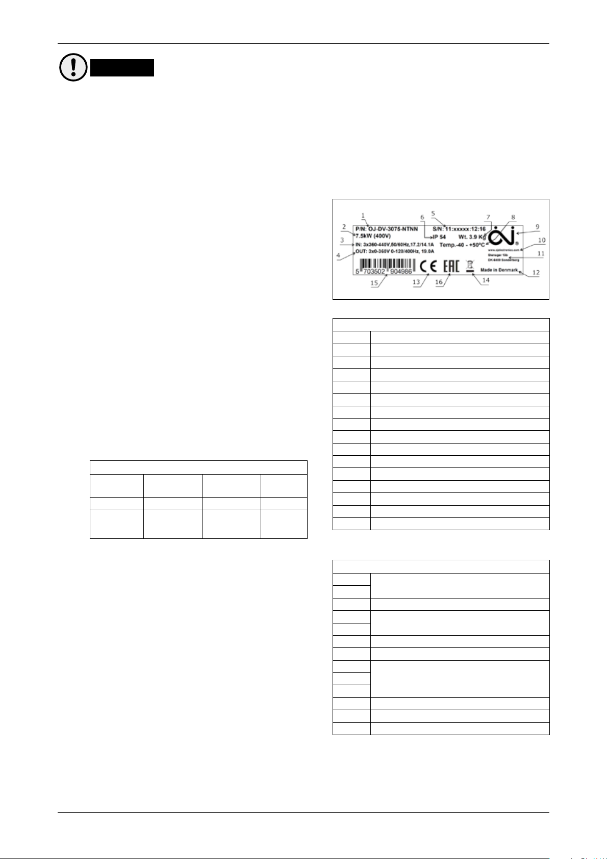
10. Rating plate
10.1. OJ-DV is equipped with a silver-coloured rating
plate.
See the example in fig. 10.1 and explanation in
table 10.2.
Check that the information specified on the rating
plate is as expected.
10.2. Rating plate, information and explanation
10.3. Explanation of product code
Each and every OJ-DV is given its own product
code during manufacture.
The product code (see table 10.3) gives precise
information on the specific OJ-DV.
The product code contains the following
information:
Table 10.3
Week number
W W B B B B B S S S S S Y Y
Week of
production
Batch Serial no. Year
Manufacturer's order
number
Unit
number
Year of
manufacture
Figure 10.1
Table 10.2
1 Product ID = see table 10.4.
2 Shaft power at nominal voltage
3 Max. input voltage, Hz/A
4 Max. output voltage/Hz/A
5 Product code = see table 10.3.
6 Enclosure rating
7 Weight
8 Temperature range, operating
9 Manufacturer's logo
10 Manufacturer's web address
11 Manufacturer's postal address
12 Country of manufacture
13 CE approved, logo
14 Disposal, logo
15 Bar code
16 EAC approved, logo
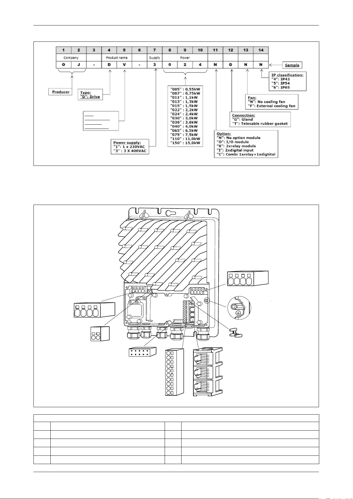
10.4. The product ID consists of a combination of 14
numbers and letters, each of which provides
information about the specific product, see fig.
10.4 and table 10.4.
© 2016 OJ Electronics A/S
Table 10.4
1
2
3
4
5
6
7
8
9
10
11
12
13
Manufacturer's initials
Product type
Electrical connection
Controller power/size
Optional module type
Cable entry
Integrated cooling fan
6
Page 7
INSTRUCTIONS OJ-DV | Installation
Figure 10.4
Type:
“V”: Ventilation
“R”: Rotor
“C”: Conveyor
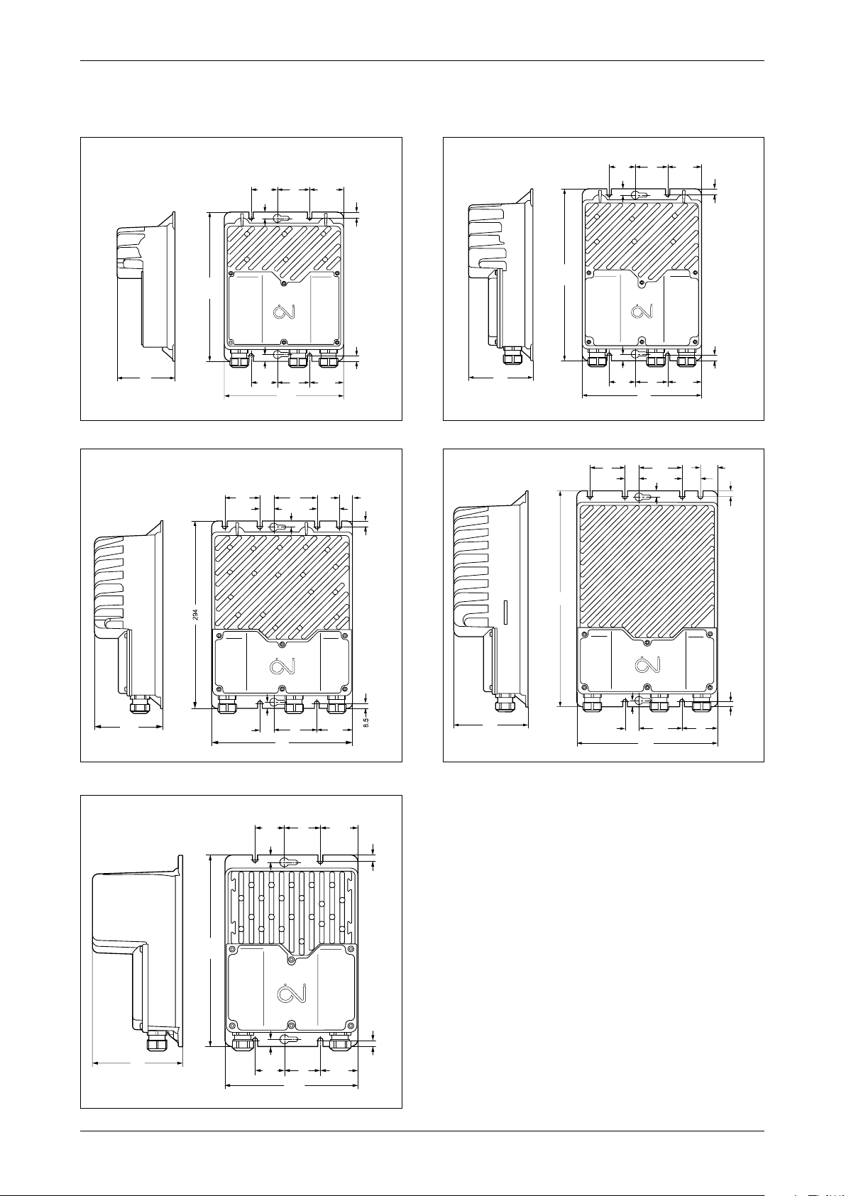
11. Exploded and dimensioned drawings
Figure 11.1
1
2
BR1014A21b
© 2016 OJ Electronics A/S
7
8
6
3
4
Table 11.1
No. Description No. Description
1 Motor connection terminals 5 RJ12 Modbus connectro (2 x xslave/1 x Master)
2 Connections for future use 6 3-point stain relief for Modbus connector cable (ribbon cable)
3 Connector for optional modules 7 Power terminals (H1=L, N, PE); (H3, H4, H5=L1, L2, L3, PE)
4 Terminal strip for Modbus and A/D control signals 8 Connector for the earth (PE) protective conductor
© 2016 OJ Electronics A/S
5
BR1014A21b
7
Page 8
INSTRUCTIONS OJ-DV | Installation
© 2015 OJ Electronics A/S
Dimensioned drawings
Figure 11.2
Figure 11.4
Figure 11.3
52.25
50
40.5
40.5
10
10
185
52.25
50
10
230.5
90
40.5
10
185
52.25
50
BR1014A25a
8.5
© 2015 OJ Electronics A/S
265.5
8.5
100
52.25
50
40.5
BR1014A25a
BR1014A23a
8.5
8.5
© 2015 OJ Electronics A/S
BR1014A23a
Figure 11.5
29.5
66.5
10
BR1014A22b
8.5
33
35
54.5
47
34.5
20.7
BR1014A24a
8.5
© 2015 OJ Electronics A/S
67
22
10
107.5
Figure 11.6
399
10
220
55.222
67
144
BR1014A24a
50 52.25
40.5
10
265.5
8.5
BR1014A43a
© 2016 OJ Electronics A/S
21.5
10
68.5
244
8.5
66
BR1014A22b
125
40.5
10
50
52.25
8.5
184.5
BR1014A43a
© 2016 OJ Electronics A/S
8
Page 9
INSTRUCTIONS OJ-DV | Installation
12. Mechanical installation
Incorrect mechanical installation may cause overheating and impaired performance.
Warning
• OJ-DV must only be installed by trained/experienced personnel.
• To ensure proper cooling of the OJ-DV, it must be positioned in such a way that the passing air
flow (> 3 m/s turbulent air speed) can cool the OJ-DV cooling fins. (3 m/s turbulent air speed is
equivalent to 6.5 m/s laminar air speed). If the OJ-DV is installed in a reduced air flow (< 3 m/s
turbulent air speed) or mounted outside a direct airstream, the output power (kW) will be reduced.
External on-board cooling fan can be added.
• Only OJ-DV-1013 can be installed without considering the above requirements for sucient air
flow over the cooling fins. OJ-DV-1013 is supplied with extra large cooling fins and can therefore
be mounted in still air with an air temperature of max. 40°C.
See Section 25: Technical Specifications.
• To facilitate future service and maintenance tasks, ensure that there is sucient space around the
unit after it has been installed.
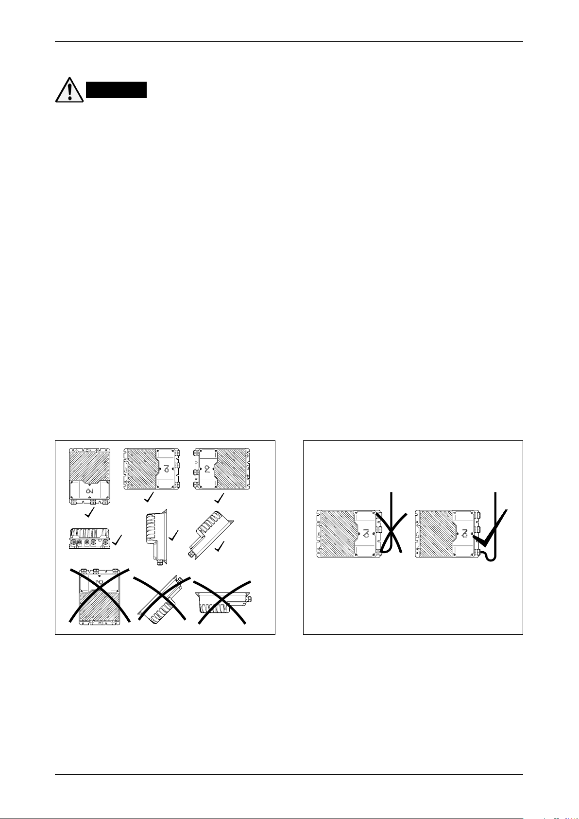
• To achieve the specified enclosure rating, the cable glands must not point upwards (see fig. 12.4).
• To prevent water from entering OJ-DV via cables and cable glands, ensure that connection is
performed in such a way that water is prevented from accumulating around the cable in the gland.
See fig. 12.5.
• Check that the surface to which OJ-DV is attached is capable of supporting the entire weight of
the unit.
• OJ-DV can be mounted vertically, horizontally or at an incline. See fig. 12.4.
• OJ-DV must be installed on a flat solid surface.
• To avoid unnecessarily long motor cables (max. 5 m), OJ-DV should be installed as close to the
motor as possible.
• Use only the pre-cut installation holes/screw holes to secure OJ-DV in place.
• Dimensioned drawings, see figs 11.2 to 11.6.
Figure 12.4
BR1014A05a
© 2015 OJ Electronics A/S
BR1014A05a
Figure 12.5
BR1014A26a
© 2015 OJ Electronics A/S
BR1014A26a
© 2016 OJ Electronics A/S
9
Page 10

INSTRUCTIONS OJ-DV | Installation
13. Electrical installation
Warning
• OJ-DV must only be installed and commissioned by trained/qualified personnel.
• Check that the data specified on the rating plate of the motor matches the data specified on the
OJ-DV rating plate.
• Incorrect electrical installation may cause a risk of severe or fatal personal injury.
Warning
13.1 Dangerous induced voltage (Windmilling)
• If natural drafts through the duct system cause the fan to rotate even when it has not received an
operating signal (called windmilling), there is a risk that the motor will induce voltage on the OJ-DV
motor terminals, making them dangerous to touch.
Caution
13.2 EMC-compliant installation
• Always use shielded cables as motor cables.
• Shielded cable is not necessary for I/O signal cables and Modbus cables.
• Cable shields must always be electrically connected to the earthed product enclosure.
• Use the internal, factory-fitted cable clamps to ensure proper shield connection.
• Never convey mains voltage, motor connections and control signals in the same cable.
• The +24 VDC from the OJ-DV is not intended to be used as power supply for third party products.
If the +24 is used for power supply to third party products, the product might not fulfill the EMC
regulations.
Note
13.3 Short-circuit protection – Power supply
• Short-circuit protection for the supply side of OJ-DV is not provided together with the product.
• Correct short-circuit protection at the power supply input side on the OJ-DV must always be used
in accordance with local and international regulations.
• Short-circuit protection equipment must as a minimum have a tripping curve “C” conforming to
IEC 60898-1.
• Short-circuit protection is supplied by the installer.
Warning
13.4 PERSONAL PROTECTION - USE OF RCDs (TT-system), DIRECT CURRENT (AC/DC) RISK
This product can cause a DC current in the ground protective conductor in the event of a ground
fault.
If the 3 phases to the OJ-DV are not switched in at exactly the same time, then there will be a
generated current in the earthing/ground conductor during the switching time until all 3 phases are
connected.
Take notice of the following precautions:
• If a residual current device (RCD) is used for extra personal protection, use only an RCD of Type
B on the supply side of this product (B type, for alternating and/or pulsating current with DC
components and continuous fault current).
• RCDs of type B must comply with all provisions of IEC 61008/9
• Protective earthing of the OJ-DV in combination with the use of RCDs must always be performed
in accordance with the relevant local and international requirements, laws and regulations
• Failure to follow these precautions can lead to severe or fatal injuries to persons and animals.
© 2016 OJ Electronics A/S
10
Page 11

INSTRUCTIONS OJ-DV | Installation
Warning
13.5 Potential equalisation
• There is a risk of electrical interference if the ground potential between the OJ-DV and the air handling
unit or duct dier from each other. In the event of potential dierences between system components,
an equalisation conductor must always be fitted.
• Recommended cable cross section: 10 mm2.
• Lugs should be used, and the equalisation conductor should be attached to the OJ-DV enclosure via
one of the screws used to mechanically install the unit.
Warning
13.6 GROUNDING HAZARD (PE) LEAKAGE CURRENT HAZARD
Follow national and local regulations regarding protective earthing of equipment with a leakage current
exceeding 3.5 mA.
The OJ-DV technology causes switching at high frequency. This will generate a leakage current in the
earth/grounding connection, PE. (PE=Protective Earth).
This ground leakage current is dependant on the dierent configurations, including RFI filtering, shielded
motor cables and the motor type.
EN/IEC61800-5-1 (Power Drive System Product Standard) requires special emphasis because the
leakage current in the OJ-DV possibly exceeds 3.5 mA. See EN60364-5-54 paragraph 543.7 (Reinforced
protective conductors for protective conductor currents exceeding 10 mA) for further information.
Earth/grounding connection must be made in one of the following 3 ways:
• When connecting only one (1) PE conductor, the minimum cross-section should be at least 10 mm2,
or
• When connecting 2 separate ground conductors, both should comply with the dimensioning rules.
• If 2 conductors are used, they must be connected to individual earth/grounding connectors in the OJ-
DV controller.
• External grounding connection. If the machine housing is approved as a grounding connector, then
the OJ-DV can be grounded to the machine.
• Grounding connectors must always be made in accordance with applicable local and international
standards and directives.
• Follow all local and national electrical regulations for earth/grounding the OJ-DV properly.
• Establish well-executed protective grounding for this OJ-DV that has a leakage current exceeding 3.5
mA.
• A dedicated ground conductor is required for input power, motor power and control wiring.
• Use the clamps and connectors on the OJ-DV for proper ground connections.
• Do not “daisy chain” the ground connection between 2 or more OJ-DV controllers.
• Keep the ground conductor connections as short as possible.
• Always use shielded cables between the OJ-DV and motor, to reduce electrical noise.
• Follow motor manufacturer wiring requirements.
.
Note
13.7 Cable requirements
• All cables and conductors used in connection with the OJ-DV must comply with local and national rules
and regulations.
• The OJ-DV product line fulfils the “residential level” for emissions as per EN-61000-6-3 and “industrial
level” for immunity as per EN-61000-6-2 with up to 5 metre shielded motor cables. (15 kW is limited
to up to 4 metre motor cables). Longer motor cables can be used but it is the installer’s responsibility
to ensure the standards in EN-61000-6-2 are complied with. Industrial level for both immunity and
emissions can be fulfilled, depending on the cable capacity as well as the motor capacity.
• A 6-core, unshielded, 30 AWG/0.066 mm² telecommunications cable can be used as a Modbus cable.
• Generally, cable types with copper conductors are recommended.
• For recommended cable dimensions, see table 13.7.
© 2016 OJ Electronics A/S
11
Page 12

INSTRUCTIONS OJ-DV | Installation
Table 13.7
Power cable
Cable gland Cable diameter Cable size, min. Cable size, max. Core sleeve/stripped min.
H1/H1x M20 6-12 mm 3x1.5 mm
H3 M20 6-12 mm 4x1.5 mm
H4 M20 6-12 mm 4x1.5 mm
H5 M25 11-18 mm 4x2.5 mm
Motor cable
Cable gland Cable diameter Cable size, min. Cable size, max. Core sleeve/stripped min.
H1/H1x M20 6-12 mm 3x1.5 mm
H3 M20 6-12 mm 4x1.5 mm
H4 M20 6-12 mm 4x1.5 mm
H5 M25 11-18 mm 4x2.5 mm
A/D control cable
Cable gland Cable diameter Cable size, min. Cable size, max. Core sleeve/stripped min.
H1/H1x M20 6-12 mm 2x2x0.7 mm
H3 M20 6-12 mm 2x2x0.7 mm
H4 M20 6-12 mm 2x2x0.7 mm
H5 M20 6-12 mm 2x2x0.7 mm
Modbus round cable
Cable gland Cable diameter Cable size, min. Cable size, max. Core sleeve/stripped min.
H1/H1x M16 4-8 mm 3x2x0.7 mm
H3 M16 4-8 mm 3x2x0.7 mm
H4 M16 4-8 mm 3x2x0.7 mm
H5 M16 4-8 mm 3x2x0.7 mm
Modbus ribbon cable
H1 ... H5: Telecommunication cable/ribbon cable, 6-core, unshielded, 30 AWG/0.066 mm²
2
2
2
2
2
2
2
2
2
2
2
2
2
2
2
2
3x2.5 mm
4x2.5 mm
4x4 mm
4x10 mm
3x2.5 mm
4x2.5 mm
4x4 mm
4x10 mm
10x2x0.7 mm
10x2x0.7 mm
10x2x0.7 mm
10x2x0.7 mm
10x2x0.7 mm
10x2x0.7 mm
10x2x0.7 mm
10x2x0.7 mm
2
2
2
2
2
2
2
2
2
2
2
2
2
2
2
2
10 mm
10 mm
10-15 mm
10-18 mm
10 mm
10 mm
10-15 mm
10-18 mm
10 mm
10 mm
10 mm
10 mm
10 mm
10 mm
10 mm
10 mm
13.8 Opening the OJ-DV
• Check that the voltage supply to OJ-DV has been disconnected before opening the cover.
• Wait approx. 3 minutes after disconnecting mains voltage before removing the cover.
• OJ-DV is opened by loosening the six Torx 20 screws holding the plastic cover in place.
• Carefully remove the loosened cover.
13.9 Cable entries – cable glands – strain relief
Figure 13.9
• The factory-fitted cable glands should be used
when inserting power, motor and control cables into
OJ-DV.
• Remember to re-tighten the cable glands to ensure
OJ-DV låg
ingress protection and strain relief.
• If Modbus communication is based on 6-core,
unshielded, 30 AWG/0.066 mm² telecommunication
Gummipakning
Modbus kabel
cable, the cable must be inserted through the
purpose-moulded rubber seal. See fig. 13.9.
• The rubber seal has a cut insertion slit and assure
1
23
the product enclosure rating if properly fitted. See
fig. 13.9.
• The Modbus cable entry features 3-point strain
relief, which must be used.
OJ-DV låg
4
-DA
BR1014A06a
© 2015 OJ Electronic A/S
BR1014A07a
© 2016 OJ Electronics A/S
12
Page 13

INSTRUCTIONS OJ-DV | Installation
© 2016 OJ Electronics A/S
Control signals
13.10 Spring terminals
• If multi-core cables/leads are used, core sleeves/
end sleeves must always be used.
• The connection terminals are spring loaded and
the stripped wire can be easily inserted into the
terminal by carefully pushing the wire into the
terminal without using tools. Alternatively, the
terminal spring can be loosened by pressing it
lightly with a screwdriver or similar implement. See
fig. 13.10.
• Solid and multi-core cables/leads can be used.
• Stripped wire ends or end sleeves must be
between 8 and 15 mm.
• Wires can be removed by carefully loosening
the terminal spring by pressing lightly with a
screwdriver or similar implement. See fig. 13.10.
13.11 Terminal and connector overview
Figure 13.11
OJ-DV
Motor
U
V
W
PE
Future use
Open
collector
BR-
BR+
Modbus
Gnd
U
V
W
PE
A
B
A
+10Vdc
0-10Vin
Gnd
Din2
Din1
Dout1
Gnd
B
C
-V+
Adr.Pin1
-Add. Pin1
-Bus B
-Bus A
Adr.Pin2
-Add. Pin2
-Gnd
Adr.Pin1
-Add. Pin1
-Bus B
-Bus A
Adr.Pin2
-Add. Pin2
-Gnd
-V+
-Gnd
-Bus B
-Bus A
-V+
-Gnd
Figure 13.10
L1
L2
L3
PE
3-Phase
connection
L1
L2
L3
PE
PE
RJ12 Modbus Slave
RJ12 Modbus Slave
RJ12 Modbus Master
e.g. PTH/VOC
2
1
BR1014A01a
© 2015 OJ Electronic A/S
1
BBR1014A01a
-GB
BR1014A03c
BR1014A03c
13.12 Motor connection
• The motor cable must be connected to the
• When the stripped wire is properly inserted into
• IMPORTANT! The motor cable must always be
• Remember to re-tighten the cable glands to
terminals marked ”U”, ”V”, ”W” and ”PE”.
the terminal (see section 13.10), the terminal
tensions automatically with the correct torque.
a shielded cable and the shield must be ended
in the clamp intended for that purpose. See fig.
13.12.
ensure ingress protection and strain relief.
© 2016 OJ Electronics A/S
Figure 13.12
BR1014A09a
© 2015 OJ Electronic A/S
8-15mm
BR1014A09a
13
Motor
BR- BR+
PE
U
VW
Page 14

INSTRUCTIONS OJ-DV | Installation
© 2016 OJ Electronics A/S
13.13 Mains voltage connection
• With 3-phase OJ-DV units, connect the power
cable to the terminals marked ”L1”, ”L2”, ”L3” and
”PE”. See fig. 13.13.1. On 1-phase OJ-DV units,
the terminals are marked ”L”, ”N” and ”PE”. See fig.
13.13.2.
• Pay special attention to section 13.6 in these
instructions, in particular:
• Earth/grounding connection must be made in one
of the following 3 ways:
• When connecting only one (1) PE conductor,
the minimum cross-section should be at least
10 mm2, or
• When connecting 2 separate ground
conductors, both should comply with the
dimensioning rules.
• If 2 conductors are used, they must be
connected to individual earth/grounding
connectors in the OJ-DV controller.
• External grounding connection. If the
machine housing is approved as a grounding
connector, then the OJ-DV can be grounded
to the machine.
• Grounding connectors must always be made
in accordance with applicable local and
international standards and directives.
• It is recommended that the PE wire is 20 mm longer
than the other wires in the cable. If the cable is
accidentally pulled out of the OJ-DV while there is
voltage on the cable and terminals, the PE wire will
then be the last to be disconnected. OJ-DV is thus
prevented from causing electric shock.
• When the stripped wire is properly inserted into the
terminal (see section 13.10), the terminal tensions
automatically with the correct torque.
• Remember to re-tighten the cable glands to ensure
ingress protection and strain relief.
Figure 13.13.1
L1
L2 L3
MAINS
8-15mm
BR1014A08b
Figure 13.13.2
BR1014A08b
PE
© 2016 OJ Electronics A/S
PE
L
N
MAINS
12mm
BR1014A27b
BR1014A27b
13.14 Modbus connection
• OJ-DV is equipped with four connectors for
Modbus connection.
• It also features 3 x RJ12 connectors and one strip
of spring terminals.
• On the terminal strip with spring terminals
for control signals (A/D I/O), the terminals for
connecting Modbus are marked ”Bus A”, ”Bus B”
and ”GND”. See fig. 13.14.1.
• If wanted, a round cable can be used for Modbus
communication, connected to terminals marked
”Bus A” and ”Bus B” on the OJ-DV terminal strip.
• The Modbus terminals are internally connected in
parallel to the Modbus pins in the RJ12 connectors
marked ”A” and ”B”.
• The three 3 RJ12 connectors are marked ”A”, ”B”
and ”C”.
• ”A”: Modbus connection, slave, +24 V voltage in
connector.
© 2016 OJ Electronics A/S
Figure 13.14.1
Bus A
Bus B
GND
+10Vdc
A
B
C
-V+
-Add. Pin1
-Bus B
-Bus A
-Add. Pin2
-Gnd
-
-Add. Pin1
-Bus B
-Bus A
-Add. Pin2
-Gnd
-V+
-Gnd
-Bus B
-Bus A
-V+
-Gnd
BR1014A16a
© 2015 OJ Electronics A/S
BR1014A16a
14
Page 15

INSTRUCTIONS OJ-DV | Installation
• ”B”: Modbus connection, slave, no +24 V voltage in connector.
• ”C”: Modbus connection, Master, external equipment, e.g. PTH/VOC. See fig. 13.11.
• A 6-core, unshielded, 30 AWG/0.066 mm² telecommunications cable or similar type of ribbon
cable can also be used for Modbus communication.
• Attach RJ12 connectors to both ends using a special-purpose tool.
• The OJ-DV is prepared to be installed in Modbus networks either in daisy chain or star
networks. Every OJ-DV has a preinstalled Modbus termination resistor of size 1 kΩ, which in
most applications would be sucient.
• Extra Modbus termination resistor is not to be used, except in installations where the Modbus
exceeds >100 m in a daisy chain Modbus connection.
• If the Modbus exceeds >100 m, it might be necessary to install an extra Modbus termination
resistor of size 180 Ω. This resistor is only to be installed in the last OJ-DV in the chain.
• In Modbus star connection installations, a Modbus termination resistor is mostly not to be used.
Note
IMPORTANT! RJ12 connectors must be fitted to the ends
in such a way that both connectors have the same colour
sequence as the cable.
See fig. 13.14.2.
13.15 A/D control signal connections
• Connect A/D control signals to the terminal strip,
see fig. 13.15.1
• For further information on using the spring
terminals, see section 13.10.
• The function/programming of A/D inputs and
outputs can be changed via Modbus.
For further information on the Modbus protocol,
contact OJ Electronics A/S
• +10Vdc = Constant + 10 VDC for control signal
and NOT intended as power supply for other
purposes.
• Short-circuit proof also short-circuit between
+24 VDC and +10 VDC
• Tolerance ± 3%
• 0-10V In = Analogue 0-10V control input for
speed
• Potentiometer, electrical connection, see fig.
13.15.2.
Figure 13.14.2
Figure 13.15.1
Bus A
Bus B
GND
+10Vdc
0-10V In
GND
Din2
Din1
Dout1
GND
Figure 13.15.2
Bus A
Bus B
GND
+10Vdc
0-10V In
GND
Din2
Din1
Dout1
GND
Same colour sequence
Samme farverækkefølge
8-15mm
A
B
C
-V+
-Add. Pin1
-Bus B
-Bus A
-Add. Pin2
-Gnd
-
-Add. Pin1
-Bus B
-Bus A
-Add. Pin2
-Gnd
-V+
-Gnd
-Bus B
-Bus A
-V+
-Gnd
BR1014A02a
© 2015 OJ Electronic A/S
BR1014A02a
BR1014A15a
© 2015 OJ Electronics A/S
BR1014A15a
BR1014A20a
© 2015 OJ Electronics A/S
© 2016 OJ Electronics A/S
BR1014A20a
15
Page 16

INSTRUCTIONS OJ-DV | Installation
• Potentiometer: min. 500 Ω, recommended
4.7kΩ
• Internal input impedance: 60 kΩ
• External controller, electrical connection,
see fig. 13.15.3
• GND = Ground (-)
• Din2 = Alarm reset (factory setting)
• Digital input
• Internal input impedance: 60 kΩ
• Electrical connection, see fig. 13.15.4
• Din1 = Start/Stop (factory setting)
• Digital input
• Internal input impedance: 60 kΩ
• Electrical connection, see fig. 13.15.4
• Dout1 = Tacho Out; Open Collector (factory
setting)
• Digital output
• Pull-up resistance range 1.5-22 kΩ
• Pull-up voltage range 0-24 V DC
• Pull-up current range 1-20 mA
• Logical low for high stability after 1 ms
• If EMC sensitive equipment is to be connected,
then an external RC filter must be mounted
with a time constant of 1 µs.
• Electrical connection, see fig. 13.15.5
• GND = Ground (-).
Figure 13.15.3
Bus A
Bus B
GND
+10Vdc
0-10V In
GND
Din2
Din1
Dout1
GND
Figure 13.15.4
Bus A
Bus B
GND
+10Vdc
0-10V In
GND
Din2
Din1
Dout1
GND
Figure 13.15.5
+10Vdc
0-10V In
Bus A
Bus B
GND
GND
Din2
Din1
Dout1
GND
Controller
+Vout
GND
Controller
Controller
+24V
BR1014A18a
© 2015 OJ Electronic A/S
AoutX
BR1014A18a
BR1014A19a
© 2015 OJ Electronic A/S
DoutX
DoutX
BR1014A19a
BR1014A17a
© 2015 OJ Electronics A/S
RΩ
BR1014A17a
13.16 Closing of OJ-DV
• When all electrical connections have been
correctly mounted, OJ-DV can be closed again
• Fasten the blue plastic cover with the associated 6
TX20 screws.
• Tightening torque on the screws in the blue cover
is 2 Nm. To ensure that the product constantly
maintains the IP enclosure rating specified for
the product, it must be ensured that the 6 TX20
screws are suciently tightened to the tightening
torque. At the same time, it must be ensured that
the tightening torque is not so high that the blue
plastic cover is deformed.
© 2016 OJ Electronics A/S
16
Page 17

INSTRUCTIONS OJ-DV | Installation
14. Checklist – mechanical and electrical installation
• Before OJ-DV is energized for the first time, installation and connection must be checked.
• Use the table below as a checklist.
Item to be checked Description of check √
Completion Check that the entire installation is ready to be commissioned, both electrically and mechanically, before
Product conformity Check that the mains voltage on the supply terminals corresponds to the rated input voltage of the OJ-
Mechanical
installation
Ambient conditions Check that requirements on the surrounding environment have been met.
Cabling Check that all cabling has been fitted correctly and that motor and control cables are kept apart in
Electrical installation Check that cables have been correctly inserted into OJ-DV and that the cable glands have been correctly
energizing the installation.
Check that no people or animals are present in the vicinity of moving parts.
DV.
Check the rating plates of the motor and OJ-DV to ensure that the units have been sized correctly.
Check that OJ-DV is correctly and securely attached to a flat surface.
See Section 12 in this manual.
Check that there is a free, unobstructed passage of air to the cooling fins.
See Section 12 in this manual.
Check that the blue plastic cover on OJ-DV is correctly mounted and that all screws are suciently
tightened before switching the power on to the product. Tightening torque on the screws is 2 Nm.
Check that all unused cable glands and other unused openings are appropriately blanked o in
accordance with the applicable enclosure rating.
Check that temperature and other environment specifications are observed.
See technical specifications, Section 25 in this manual.
separate cable conduits.
Check that the motor cable is a shielded cable and that its length is no longer than 5 metres.
Check that all cables are securely attached and relieved of tension and torsion.
tightened.
Check that the OJ-DV voltage supply terminals have been connected to the correct mains voltage level.
Check that all cables are correctly ended and securely attached.
Check that all cables are free of visible damage throughout their length.
Check whether there are any loose connections, which may cause overheating and serious damage to
the product and property.
Mains voltage Check that the mains voltage wires have been correctly fitted to the supply terminals: one-phase on
Motor connection Check that motor cables are correctly connected to ”U”, ”V”, ”W” and ”PE” – and check that tightening
Control and signal
wires
Shield Check that the motor cable shield is ended correctly and use continuity measurement to check that the
Fuses and circuit
breakers
Earthing Check that all earth connections in the motor and OJ-DV are correctly connected and free of oxidation.
terminals ”L”, ”N” and ”PE” and three-phase on terminals ”L1”, ”L2”, ”L3” and ”PE”.
Check by means of voltage measurement that there is the correct voltage on the terminals.
Check short-circuit protection and supplementary protection.
torque is correct on the spring terminals of the motor.
Check that control cables are ended correctly and securely attached.
Check that both ends of the Modbus cable have been attached to the correct connectors.
shield is connected to an active earth connection at both ends.
Check that active short-circuit protection has been correctly fitted and sized.
Check that all safety equipment is operative and set correctly.
Check by means of continuity measurement that the earth connection is active and that the contact
resistance complies with applicable local and international directives and regulations.
© 2016 OJ Electronics A/S
17
Page 18

INSTRUCTIONS OJ-DV | Operation
15. Hand terminal (Hterm) – connection and functions
• The OJ-DV range can be connected to an OJ-DV Hterm hand terminal via Modbus RJ12
connector ”A”. See fig. 15.1.
• If an OJ-DV Hterm is connected, the hand terminal will act as master and the OJ-DV as slave.
• Only one master at a time can be connected to the RJ12 connectors marked ”A” and ”B”. It
is thus not possible to connect both a hand terminal to connector ”A” and an active Modbus
communication cable to connector ”B” at the same time.
• OJ-DV Hterm has the following menu options:
• Status: Control and operating parameters
for connected OJ-DV
• Setup: Setting application parameters
• Alarm: Read-out of alarm log for connected
OJ-DV
• Modbus: Changing Modbus settings for OJ-
DV
• About: Read-out of software version no.
and type for connected OJ-DV
• Config: Changing OJ-DV/motor settings
Note
For further information on OJ-DV Hterm operation and
menus, contact OJ Electronics A/S.
Figure 15.1
A
B
C
-V+
-Add. Pin2
-Bus B
-Bus A
-Add. Pin2
-Gnd
-
-Add. Pin2
-Bus B
-Bus A
-Add. Pin2
-Gnd
-V+
-Gnd
-Bus B
-Bus A
-V+
-Gnd
BR1014A11a
© 2015 OJ Electronic A/S
BR1014A11a
16. PCTool – connection and functions
• The OJ-DV range can be configured using OJ-DV PCTool, which must be connected to Modbus
RJ12 connector ”B”.
• OJ-DV PCTool allows motor and controller parameters to be viewed and set, including:
• Status: Control and operating parameters for connected OJ-DV
• Setup: Setting application parameters
• Alarm: Read-out of alarm log for connected OJ-DV
• Modbus: Changing Modbus settings for OJ-DV
• About: Read-out of software version no. and type for connected OJ-DV
• Config: Changing OJ-DV/motor settings
• Log data: Read-out of log files
• Firmware: Updating firmware
• Motor: Configuring motor parameters
• Fan: Configuring fan parameters
• Hardware: Configuring OJ-DV hardware
OJ-DV PCTool is used solely by fan and system manufacturers.
For further information on OJ-DV PCTool operation and menus, contact OJ Electronics A/S.
17. Optional modules – connection and function
• Various optional modules can be connected to OJ-DV, providing extra versatility where the unit is
to be built into systems and applications that require additional inputs and outputs.
For further information on the possibilities oered by optional modules, contact OJ Electronics A/S.
© 2016 OJ Electronics A/S
18
Page 19

INSTRUCTIONS OJ-DV | Functions
18. Functions
18.1 Analogue/digital control
• OJ-DV can be controlled via analogue/digital (A/D) inputs or via Modbus.
• The factory setting is analogue/digital (A/D) control.
• Connect A/D control signals to the terminal strip, see section 13.15.1.
0-10V In
• Is used to control motor speed in relation to a 0-10V signal.
Note
• With A/D control, functions such as alarm read-out and acknowledgement are still possible via
Modbus even though "Modbus control" is not activated.
• The relationship between the 0-10V control signal and motor speed depends on the settings for
min./max. speed and ramp up/ramp down times. See figs 18.1 and 18.2.
• The ”+10Vdc”, ”0-10V In” and ”GND” terminals can be connected to a potentiometer, see
electrical connection in fig.13.15.2.
The function of the digital inputs and outputs has been defined by OJ Electronics A/S as follows:
• Din1 = Start/Stop (1 = Start)
• Din2 = Alarm reset (1 = Alarm reset)
• Dout1 = Tacho Out (1 pulse per motor revolution)
Note
The digital inputs and outputs can be given alternative functions via Modbus.
Relationship between control signal (0-10V In) and speed –
see fig. 18.1.
The control signal regulates motor speed between the set
minimum and maximum speeds (AC motor=Hz; PM/BLDC
motor=rpm) and the set ramp times – see fig.18.2.
18.2 Modbus control
• OJ-DV can be controlled via Modbus
commands according to the Modbus protocol.
• Control of motor speed via Modbus
communication is factory disabled.
• If OJ-DV is to be controlled via Modbus,
Coil Stat Bit register 8 must be set to ”0” =
”Modbus control”.
• Other functions, such as alarm read-out
and acknowledgement, are still possible via
Modbus even though "Modbus control" is not
activated.
• NOTE! Contact OJ Electronics A/S if you
require the Modbus protocol.
•
18.3 Switching frequency
Switching frequency is crucial in determining the
amount of audible acoustic noise emitted by OJ-DV.
The higher the switching frequency, the less audible
noise will be emitted by OJ-DV. At the same time,
however, internal losses will be increased, reducing
eciency.
Figure 18.1
Frequency/revolutions
Frekvens/
omdrejninger
Max. Hz/Rpm
Min. Hz/Rpm
0%
0V
Figure 18.2
Speed out
Max. Speed
Min. Speed
Setpoint
100%
0%
Up
Ramp
100%
9.5V
Down
Ramp
-DA
BR1014A13a
© 2015 OJ Electronics A/S
Setpoint
BR1014A13a
-GB
BR1014A12a
© 2015 OJ Electronic A/S
Time
Time
BR1014A12a
© 2016 OJ Electronics A/S
19
Page 20

INSTRUCTIONS OJ-DV | Functions
OJ-DV can be set to operate constantly with a switching frequency of either 4 kHz or 8 kHz, or it
can be set to change switching frequency automatically depending on motor speed (AUTO setting).
Switching frequency (switching mode) is set via Modbus:
• Setting ”4kHz” = Constant 4kHz switching frequency
• Setting ”8kHz” = Constant 8kHz switching frequency
• Setting ”AUTO” = Switching frequency is changed automatically:
• At motor speeds higher than 60% of rated speed, switching frequency is changed to 4 kHz
• At motor speeds lower than 50% of rated speed, switching frequency is changed to 8 kHz
18.4 Braking power
• The electronics within OJ-DV can as a starting point supply braking power corresponding to its
own consumption. It is expected that an air flow capable of maintaining typically up to 30% of
nominal fan speed can be braked by this function.
18.5 Fire mode
• Fire mode designates a function in which OJ-DV is kept operating by an emergency program
which disables the alarm monitor.
• The fire mode function can be activated via Modbus or via digital input.
• Among other things, the function can be used in connection with smoke extraction from a burning
property. When fire mode is activated, an extraction fan will continue to remove smoke from the
property for as long as possible.
• In fire mode, OJ-DV is able to maintain operation for at least an hour even when OJ-DV and the
fan motor are overheated (max. 70°C).
• Upon activation of fire mode operation the output signal to the motor remains the same value as it
was just before the fire mode condition was activated, and any alarms will be suppressed.
• During fire mode operation the output signal to the motor will at any time be the selected voltage
of 0-10V input, or if the OJ-DV is controlled via Modus, it will be the control signal from a potential
Modbus Master. If there is a communication failure on the Modbus, the output signal to the motor
will be the same value as it was just before the Modbus communication was disconnected.
• If the motor is not operating when fire mode is activated, the motor will remain stopped upon
activation of fire mode.
18.6 Frequency converter mode – for asynchronous motors
The OJ-DV factory-set to frequency converter mode for
standard asynchronous induction motors (AC-IM) and
the control mode is 0-10VDC input.
This can be changed using the OJ-DV-PCTool or OJ-
DCV-HTERM (Hand terminal).
If you use the OJ-DV in frequency converter mode, you
must connect a standard 3 phase~ AC-IM motor. Pay
special attention to the information that you will find on
the nameplate of the motor.
The voltage output from the OJ-DV is for the OJ-
DV-1005…..OJ-DV-1011 maximum 250 VAC.
For the OJ-DV-3015…..OJ-DV-3150 the maximum
voltage output is 364 VAC.
If the supply voltage is higher than the rated voltage of
the single windings in the connected motor, then the
motor will be damaged.
Pay special attention if the motor is connected in “star”
or “delta” connections.
On a standard AC-IM motor, the “star”/“delta”
connection often can be changed by rearranging
the jumpers on the motor terminal, see figure 18.6.
With the OJ-DV in frequency converter mode, it is the
installer’s responsibility to enter the correct control and
motor parameters.
Figure 18.6.1
BR1014A41a
© 2016 OJ Electronics A/S
BR1014A41a
© 2016 OJ Electronics A/S
20
Page 21

INSTRUCTIONS OJ-DV | Functions
Pay special attention to the following parameters:
Minimum frequency Even if the control signal is e.g. 0% or 0.0V and the OJ-DV has an activated start signal, the motor will not
run slower than the value in this parameter.
Maximum frequency Even if the control signal is e.g. 100% or 10.0V and the OJ-DV has an activated start signal, the motor will
not run faster than the value in this parameter.
Ramp-up time Ramp-up time is the time (in seconds) from when the OJ-DV gets the start signal until the speed has been
reached according to the setpoint. The ramp-up time is used to avoid overload and damage to the controller
and motor. The ramp-up time is also used in upward jumps between speed setpoints.
If this ramp-up is too short, the OJ-DV could possibly trigger a current limit alarm
Ramp-down time. Ramp-down time is the time (in seconds) from when the OJ-DV receives a stop signal until the motor comes
to a halt. The ramp-down time is used to avoid overload and damage to the controller and motor. Rampdown time is also used in connection with downward jumps between speed setpoints.
If this ramp-down is too short, the OJ-DV will use power to stop or slow down the motor. This could possibly
trigger a current limit alarm from the OJ-DV.
Switch frequency Switch frequency is a parameter that has an influence on the eciency and the audible noise from the con-
nected motor and/or the OJ-DV controller.
In the OJ-DV it is possible to select “Auto”, “4 kHz” or “8 kHz”.
Activating the “Extra high” Modbus parameter makes it possible to select “Auto”, “4 kHz” or “10 kHz”.
The higher the switch frequency, the lower the audible noise from the OJ-DV controller system, but the consequence of lower audible noise is decreasing eciency of the OJ-DV controller system.
In “Auto” the OJ-DV will automatically switch between “4 kHz” and “8/10 kHz”. During start-up from 0 – 60%
speed, the switch frequency will be “8/10 kHz” and this will make for less audible noise from the connected
motor and/or the OJ-DV controller. When the speed has increased and passes 60%, the switch frequency
will then switch to “4 kHz”. The noise from the fan and airflow will now drown out the audible noise from the
OJ-DV controller system.
In the speed-down sequence, the OJ-DV will switch to “8/10 kHz” when the speed of the motor passes 50%
downwards.
It is also possible to select a fixed switch frequency of “4 kHz” or “8/10 kHz”.
U-min Hz This parameter selects the voltage to the motor at minimum frequency.
Freq U-max This parameter selects the frequency to the motor at maximum voltage.
V/F characteristic The “V/F characteristic” parameter is a parameter
that makes it possible to change the ratio between
voltage and frequency for the motor.
The “V/F characteristic” is factory-set to the value 0
(zero), which means that the ratio between the voltage and the frequency is linear.
At the other end, the value “100” is equal to a parabolic relation between voltage and frequency.
For a standard fan application, the value of the “V/F
characteristic” should be 75. AC motors with poor
eciency require a higher “V/F characteristic”.
Figure 18.6.2
For further information about parameters in the OJ-DV, see OJ-DV Modbus protocol.
18.7 Electronically commutated mode (EC mode) – for PM and BLDC motors
The OJ-DV factory-set to frequency converter mode for standard asynchronous induction motors
(AC-IM) and the control mode is 0-10 VDC input.
This can be changed using the OJ-DV-PCTool or OJ-DCV-HTERM (Hand terminal).
The dierence between an AC-IM motor and a PM-SM/BLDC is basically the rotor.
In the PM-SM/BLDC motor, the windings in the rotor are replaced with permanent magnets, but
the control system has to be and is very dierent. Due to the permanent magnets in the rotor, they
will induce voltage in the stator windings as they rotate and as a result also voltage back to the
controller. This is what is called back EMF (EMF = electromotive force) and describes an important
and special characteristic of the motor.
The controller has to be able to handle this back EMF and that is why you cannot control a PM-SM/
BLDC motor with an OJ-DV controller in frequency converter mode.
© 2016 OJ Electronics A/S
21
Page 22

INSTRUCTIONS OJ-DV | Functions
Before operation, select and load the correct fan and motor parameter files using the OJ-DV
Handterminal or OJ-DV-PCTool. It is the installer’s responsibility to enter the correct control and
motor parameters.
Pay special attention to the following parameters:
Minimum rpm Even if the control signal is e.g. 0% or 0.0V and the OJ-DV has an activated start signal, the motor will not
run slower than the value in this parameter.
Maximum rpm Even if the control signal is e.g. 100% or 10.0V and the OJ-DV has an activated start signal, the motor will
not run faster than the value in this parameter.
Ramp-up time Ramp-up time is the time (in seconds) between the OJ-DV gets the start signal until the speed has been
reached according to the setpoint.
The ramp-up time is used to avoid overload and damage to the controller and motor. The ramp-up time is
also used in upwards jumps between speed setpoints.
If this ramp up is too short, the OJ-DV possibly could trigger an current limit alarm.
Ramp-down time Ramp-down time is the time (in seconds) from when the OJ-DV receives a stop signal until the motor comes
to a halt. The ramp-down time is used to avoid overload and damage to the controller and motor. Rampdown time is also used in connection with downward jumps between speed setpoints.
If this ramp-down is too short, the OJ-DV will use power to stop or slow down the motor. This could possibly
trigger a high voltage alarm (Vhi), from the OJ-DV.
Switch frequency Switch frequency is a parameter that has an influence on the eciency and the audible noise from the con-
nected motor and/or the OJ-DV controller.
In the OJ-DV it is possible to select “Auto”, “4 kHz” and “8 kHz”.
The higher the switch frequency, the lower the audible noise from the OJ-DV controller system, but the consequence of lower audible noise is decreasing eciency of the OJ-DV controller system.
In “Auto” the OJ-DV will automatically switch between “4 kHz” and “8 kHz”. During start-up from 0 - 60%
speed, the switch frequency will be “8kHz” and this will make for less audible noise from the connected
motor and/or the OJ-DV controller. When the speed has increased and passes 60%, the switch frequency
will then switch to “4 kHz”. The noise from the fan and airflow will now drown out the audible noise from the
OJ-DV controller system.
In the speed-down sequence, the OJ-DV will switch to “8 kHz” when the speed of the motor passes 50%
downwards.
It is also possible to select a fixed switch frequency of “4 kHz” or “8 kHz”.
In the speed-down sequence, the OJ-DV will switch to “8/10 kHz” when the speed of the motor passes 50%
downwards.
It is also possible to select a fixed switch frequency of “4 kHz” or “8/10 kHz”.
For further information about parameters in the OJ-DV, see OJ-DV Modbus protocol.
19. Built-in protection
• If the temperature inside OJ-DV exceeds 95°C, OJ-DV will attempt to reduce its internal heat
generation by reducing motor speed (rpm).
• OJ-DV has built-in current limitation for the protection of motor and cables and cannot therefore
supply more current than it is set to.
• In the event of lacking phase on the supply input, OJ-DV will reduce speed and activate a non-
critical alarm.
• The OJ-DV motor output terminals are short-circuit protected against phase-to-phase short
circuiting.
20. Alarms
• OJ-DV has a built-in alarm monitor, which monitors optimal fault-free operation and triggers an
alarm if operating or performance problems are observed.
• Alarms are either ”Critical” alarms or ”Non-critical” alarms.
• ”Critical” alarms stop the motor.
• ”Non-critical” alarms reduce motor performance.
• The built-in alarm monitor stops the OJ-DV.
• If the alarm situation passes, the alarm is automatically reset and OJ-DV restarted.
• If the maximum number of restarts (5 times/60 min) is exceeded, the alarm must be reset
manually.
© 2016 OJ Electronics A/S
22
Page 23

INSTRUCTIONS OJ-DV | Alarms
• The alarm can be reset by means of a Modbus command.
• The alarm is automatically reset if the power is disconnected for longer than 60 seconds.
• Alarms can be read via Modbus, see Modbus protocol.
• Alarm overview, see table 20.
Table 20
Alarm overview Trigger Alarm priority Motor operation/
response
Supply voltage too low
Supply voltage too high
The motor’s power use is too high
Internal temperature in OJ-DV too high (>95 °C)
Phase error; one or more phases disconnected
(L1, L2, L3)
Blocked rotor
Motor power has reached it’s limit
Earth fault
(Only OJ-DV-3110 & OJ-DV-3150)
Running in the wrong direction
Fault in internal EEPROM circuit
Stopped after 5 re-start attempts within 60min N/A
Phase error in motor supply (U, V, W)
Internal communication fault
Ripple voltage too high
External 24VDC supply overloaded.
✓ Supply voltage to OJ-DV is too low.
✓ OJ-DV is mistakenly connected to
mains voltage 3 x 230VAC.
✓ Supply voltage to OJ-DV is too high.
✓ Short circuit in motor cable.
✓ Short circuit in one or more motor
windings.
✓ Cooling of OJ-DV enclosure too low.
✓ Insucient air circulation around
OJ-DV.
✓ Air temperature around OJ-DV is
too high.
✓ Missing phase in supply voltage to
OJ-DV
✓ Large imbalance in supply voltage.
✓ The rotor is unable to rotate due to
a mechanical blockage of the rotor
or fan.
✓ OJ-DV has reached the limit for
maximum output power.
✓ The connected motor is larger than
allowed for the chosen OJ-DV
✓ The load is too big for the
connected motor.
✓ Earth fault on motor cables or motor
windings
✓ Windmilling in the opposite direction
during the start up process.
✓ Incorrectly chosen configuration file
- tried to download a configuration
file which is not contained in OJ-DV
✓ OJ-DV is defective.
✓ One or more motor phases / motor
cables is disconnected.
✓ One or more motor windings is
disconnected.
✓ During the process of updating
the MOC configuration file,
communication was inadvertently
disconnected.
✓ If the alarm goes o during normal
operation, it usually indicates a
defective OJ-DV.
✓ Imbalance on voltage supply.
✓ Overloading or short circuit on +24V
voltage supply.
”NC” ”RP”
”C” ”SA5”
”C” ”SA5”
”NC” ”RP”
”C” ”SA5”
”C” ”SA5”
”NC” ”RP”
”C” ”SA5”
”C” ”SA5”
”NC” ”RP”
”C” ”S”
”C” ”SA5”
”C” ”SA5”
”NC” ”RP”
”NC” ”RP”
Abbreviations:
”C”=Critical alarm
”NC”=Non-critical alarm
”RP”=Reduced performance
”SA5”=Motor stops after 5 restarts caused by same fault within 60 min
”S”=Motor stops immediately
© 2016 OJ Electronics A/S
23
Page 24

INSTRUCTIONS OJ-DV | Maintenance and troubleshooting
LED indications
• OJ-DV is equipped with a two-colour LED which
Figure 18.5
LED
indicates operating status.
• The LED is located on the underside of OJ-DV
beside the entry for the mains cable.
See fig. 18.5.
• Lights constantly green when mains voltage is
connected
• Flashes green when Modbus communication is
active
• Lights constantly red when at least one critical
alarm is active
• Flashes red when at least one non-critical
alarm is active
21. Modbus addressing of OJ-DV
Modbus addressing of OJ-DV can be accomplished in two dierent ways.
• Via the addressing pins of the ”A” or ”B” connectors – see fig. 13.14.1 and table 20.1.
Table 20.1
Add.
Pin. no.
0X36 (54 dec) 0X37 (55 dec) 0X38 (56 dec) 0X39 (57 dec)
BR1014A06a
© 2015 OJ Electronic A/S
BR1014A06a
Add.Pin1
Add.Pin2
= No connection between ”GND” and Add.Pin1/ Add.Pin2
= Connection between ”GND” and Add.Pin1/ Add.Pin2
• Via OJ-DV PCTool, where OJ-DV can be set to other Modbus addresses – see instructions for OJ-
DV PCTool.
Modbus protocol
• Contact OJ Electronics A/S if you require a complete Modbus protocol.
22. Maintenance
22.1. OJ-DV is maintenance free under normal operating conditions and load profiles.
22.2. The cooling fins must be kept free of dust, dirt and other foreign matter so that air can pass freely
over them. Deposits of dust, dirt or other foreign matter on and between the cooling fins will prevent
cooling of the OJ-DV and thus impair performance.
Caution
22.3. The cooling fins may become very hot. (Max. 95°C under normal operating conditions.)
Warning
22.4. OJ-DV cannot be repaired on site. Never attempt to repair a defective unit. Contact your supplier to
obtain a replacement.
22.5. Additional technical data are available on request from OJ Electronics A/S.
© 2016 OJ Electronics A/S
24
Page 25

INSTRUCTIONS OJ-DV | Maintenance and troubleshooting
23. Troubleshooting
Warning
23.1. Before opening OJ-DV, the mains voltage must be disconnected for at least 3 minutes to ensure
there is no risk of dangerous residual currents in electronic circuits or capacitors.
23.2. If natural drafts through the duct system cause the fan to rotate even though it has received no
operating signal, there is a risk that the motor will induce voltage on the OJ-DV motor terminals,
making them dangerous to touch.
23.3. Troubleshooting when OJ-DV is controlled via A/D signals:
Symptom Cause Action
Motor inoperative Lacking supply voltage Check the voltage supply to OJ-DV terminals ”L” and ”N” on 230V
models (H1) or terminals ”L1”, ”L2” and ”L3” on 3x400V and 3x230V
models (H3…H5).
(Nominal supply voltage is stated on the rating plate.)
Check whether short-circuit protection has been activated.
Check that the voltage supply to OJ-DV has not been cut o by
other components.
Poor electrical connections Check electrical connections.
Wrong motor for OJ-DV setup Check that the correct motor settings have been read into and stored
in the OJ-DV setup.
Lacking operating signal A/D control:
Check that OJ-DV can receive an operating signal.
With A/D control, OJ-DV must have a signal connected to the "Start/
Stop" input – digital input Din1 or Din2 depending on the setup.
Lacking 0-10VDC control signal Check that an operating signal is connected to ”0-10V In”.
Potentiometer control:
Check that the potentiometer is correctly connected to
terminals ”+10Vdc”, ”0-10V In” and ”GND” on the terminal strip.
Active alarm Read out active alarms and remedy their cause.
The motor has been stopped 5 times
by the built-in motor protector
because of overloading or other
alarm
Defective OJ-DV controller Replace OJ-DV.
Defective motor Replace motor.
Motor running in
wrong direction
Symptom Cause Action
OJ-DV noisier than
acceptable
Wrong phase sequence in motor
cable
Switching frequency too low Increase switching frequency.
Reset the alarm by short-circuiting the ”Alarm reset” input – digital
input Din1 or Din2 depending on the setup.
The alarm can also be reset by disconnecting the power supply to
the OJ-DV and reconnecting it after approx. 60 seconds.
Never attempt to repair a defective OJ-DV controller.
Contact your supplier for replacement/repair.
Interchange two phase wires on the motor or the OJ-DV terminal strip.
0 = Auto
1 = Low = 4 kHz
2 = High = 8 kHz
Increasing switching frequency increases losses within OJ-DV, thus
reducing eciency.
OJ-DV switching frequency can be changed via OJ-DV Hterm or via
Modbus.
© 2016 OJ Electronics A/S
25
Page 26

INSTRUCTIONS OJ-DV | Maintenance and troubleshooting
Symptom Cause Action
OJ-DV cuts out due
to an alarm
At least one alarm active Use OJ-DV Hterm to view the alarm and determine which alarm has
stopped the controller/motor.
Reset the alarm by short-circuiting the ”Alarm reset” input – digital
input Din1 or Din2 depending on the setup.
The alarm can also be reset by disconnecting the power supply to
the OJ-DV and reconnecting it after approx. 60 seconds.
The alarm is re-activated after reset Use OJ-DV PCTool to view the alarm and determine which alarm has
stopped the controller/motor.
Remedy the cause of repeated alarm activation.
23.4. Troubleshooting when OJ-DV is controlled via Modbus:
Symptom Cause Action
Motor inoperative Lacking supply voltage Check the voltage supply to OJ-DV terminals ”L” and ”N” on 230V
models (H1) or terminals ”L1”, ”L2” and ”L3” on 3x400V and 3x230V
models (H3…H5).
(Nominal supply voltage is stated on the rating plate.)
Check whether short-circuit protection has been activated.
Check that the voltage supply to OJ-DV has not been cut o by
other components.
Poor electrical connections Check electrical connections.
Wrong motor for OJ-DV setup Check that the correct motor settings have been read into and stored
in the OJ-DV setup.
Lacking operating signal Check that OJ-DV can receive an operating signal.
Coil Stat Bits Register 0X0001: Motor start/stop (1=On).
Lacking % control signal from Modbus controller
The motor has been stopped 5
times by the built-in motor protector
because of overloading
Defective OJ-DV controller Replace OJ-DV.
Defective motor Replace motor.
Check the Modbus control signal at Modbus address: Holding registers; Register 3X0001: PrcSet 0-10000 (0-100%).
Reset alarm: Coil Stat Bits Register 0X0002: Reset (1 pulse = Reset).
The alarm can also be reset by disconnecting the power supply to
the OJ-DV and reconnecting it after approx. 60 seconds.
Never attempt to repair a defective OJ-DV controller.
Contact your supplier for replacement/repair.
Motor running in
wrong direction
OJ-DV noisier than
acceptable
OJ-DV cuts out due
to an alarm
Wrong phase sequence in motor cable
Switching frequency too low Increase switching frequency.
At least one alarm active Use OJ-DV Hterm to view the alarm and determine which alarm has
The alarm is re-activated after reset Read out the alarm via Modbus registers and determine which alarm
Interchange two phase wires on the motor or the OJ-DV terminal strip.
0 = Auto
1 = Low = 4 kHz
2 = High = 8 kHz
Increasing switching frequency increases losses within OJ-DV, thus
reducing eciency.
OJ-DV switching frequency can be changed via OJ-DV Hterm or via
Modbus.
stopped the controller/motor.
Reset the alarm by short-circuiting the ”Alarm reset” input – digital
input Din1 or Din2 depending on the setup.
The alarm can also be reset by disconnecting the power supply to
the OJ-DV and reconnecting it after approx. 60 seconds.
has stopped the controller/motor.
Remedy the cause of repeated alarm activation.
© 2016 OJ Electronics A/S
26
Page 27

INSTRUCTIONS OJ-DV | Maintenance and troubleshooting
24. Disposal
• OJ-DV contains electronic components and must not be disposed of together with
household waste.
• OJ-DV must be disposed of in accordance with applicable local rules and regulations.
• OJ-DV meets the requirements on marking of electronic waste contained in the
European WEEE Directive 2012/19/EU.
© 2016 OJ Electronics A/S
27
Page 28

INSTRUCTIONS OJ-DV | Technical specifications
25. Technical specifications
Type DV-1005 DV-1007 DV-1011 DV-1013 DV-3015 DV-3024 DV-3030 DV-3040 DV-3055 DV-3065 DV-3075 DV-3110 DV-3150
Enclosure H1 H1x H3 H4 H5
Power size kW 0.5 0.75 1.1 1300 1.5 2.4 3.0 4.0 5.5 6.5 7.5 11 15
Eciency % > 94% > 96,5% > 96,5% > 97%
Power supply
Voltage VAC 1 x 230 VAC 50/60 Hz +/-10% 3 x 400 VAC 50/60 Hz +/-10%
Supply current at max. load A 3.0 4.4 6.5 8.5 3.1 5.0 6.3 8.4 11.5 13.6 15.7 24.4 33
Power factor
(cos-phi) at max. load
Motor output
Nominal motor power (on shaft) *1 kW 0.5 0.8 1.15 1.3 1.5 2.4 3.0 4.0 5.5 6.5 7.5 11 15
Frequency Hz AC motor: 0-120 | PM motor: 0-400
Max. output voltage Vrms 3 x 0 - 250 VAC 3 x 0 - 364 VAC
Max. output current Arms 2 3.2 4.5 5.2 4.5 6.4 8.0 10.0 12.0 15.0 19.0 27 35.0
Protection
Max. fuse A 16 32
Motor output Short-circuit protected between phases
Motor Protected by current limit
Impulse protection Protected against transient voltages by VDR
Over-voltage protection Yes, 400 V (PTC) Yes, 565 V
Overload protection Current and temperature overload protection
Environment
Operating temperature °C -40°C to +50°C
Starting temperature °C -40°C to +50°C
Storage temperature °C -40°C to +70°C
Dimensions mm 185 x 230.5 x 90 mm
Protection rating IP 54 & 65
Enclosure material Aluminium
Front cover Plastic
Weight kg 2.0 3.6 3.0 3.9 9.5
Humidity % rh 10-95% rh, non-condensing
Surface Corrosion resistant to EN/ISO 12944-2:1998 Category C4
Air flow / cooling
Interfaces
Digital communication MODBUS RTU RS485 (baud rate: 9.6, 19.2, 38.4, 115.2 Kbaud)
Digital communication Slave 2 x RJ12 & 2 x spring terminals
Digital communication Master 1 x RJ12 connection
Analogue In1 0-10 VDC, 100% @ 9.5 V DC +/-2%
Analogue Out1 +10 VDC
Digital In1 Start/stop with internal pull-up
Digital In2 Alarm reset
Digital Out1 Tacho: 1 pulse/revolution | Alarm/running signal
Green LED Lit: Power connected | Flashing: Active communication
Red LED Flashing: Alarm but still running | Constantly lit: Critical alarm - stop motor
Features
Technology Sinusoidal back-EMF signal controlled via FOC (Field Oriented Control)
Flying start Yes, < 30% of max. speed
Ramp-up time sec. 15-300
Ramp-down time sec. 15-300
Alarm Yes
Alarm reset Via digital input, MODBUS or powering down for more than 60 seconds
Fan stop sec. The braking system stops the fan as quickly as possible. Braking time will depend on the inertia of the fan.
Service data log Operating hours, alarms, loads, software version, max. temp., max. motor voltage, max. motor current, max. ripple voltage, max. ripple current
Software updating Yes, via serial interface
Motor parameters Preprogrammed by OJ or on-site configuration
Fire mode Nominal power for 1 hour at 70°C ambient temperature
Field weakening Yes
Short-circuit protection Ye s
Integrated EMC filters Ye s
Approvals
EMC EN 61800-3 (C1 & C2)
LVD EN 61800-5-1
Product standard EN 61800 Part 2
RoHS Directive Yes
Product approvals CE
Data are valid at: nominal supply voltage, +25°C and sucient air flow
Note 1: Motor Power Factor = 0.8 and eciency = 90%
> 0.99 (Active PFC) > 0.9
185 x 265
x 125 mm
Turbulent air speed of min. 3 m/s to achieve max. output power at max. ambient temperature.
Turbulent air speed below 3m/s and higher ambient temperature might lead to reduced output power.
185 x 265 x 100 mm 220 x 294 x 107 mm 244 x 399 x 144 mm
(3m/s turbulent air speed is equivalent to 6,5m/s laminar air speed)
OJ Electronics A/S
Stenager 13B • DK-6400 Sønderborg
Tel. : +45 73 12 13 14 • Fax +45 73 12 13 13
oj@ojelectronics.com • www.ojelectronics.com
The trademark is a registered trademark belonging to OJ Electronics A/S · © 2016 OJ Electronics A/S
28
 Loading...