

Page 1
1
© 2010 OJ Electronics A/S
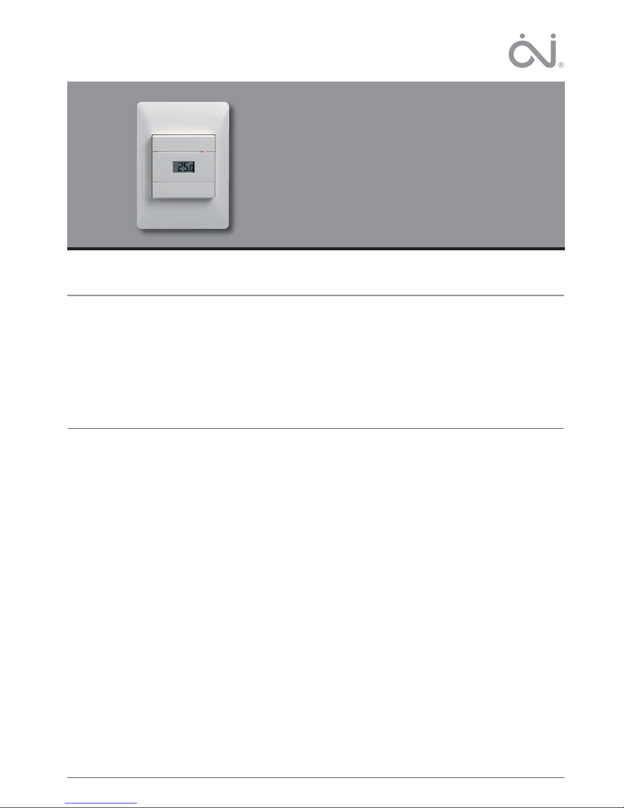
Type MTC2 / MTD2
with room or fl oor sensor
67039 02/10 (DJU)
© 2010 OJ Electronics A/S
USER MANUAL
Contents
Introduction
MICROLINE electronic thermostat for installation in standard wall
box. The thermostat allows the required temperature to be set within the range 0-40°C. An LED indicates whether heating is active.
The thermostat is suitable for ELKO and NORWESCO systems
S-16, RS-16 and UNI-10.
Product programme
MTC2-1991 with fl oor sensor
MTC2-1999 with built-in room sensor
MTD2-1999 with built-in room sensor and external limitation
sensor
CE marking
Applied standards
EN 61000-6-3, EN 61000-6-2, EN 60 730-1 and EN 60730-2-9.
The product may only be used if the complete installation complies
with current directives.
The thermostat must only be installed by an authorised electrician.
If the product has been damaged in any way, e.g. during transport,
it must be inspected and checked by authorised personnel before
being connected to the power supply.
The product carries a manufacturer’s warranty if installed in accordance with these instructions and applicable regulations.
Type MTC2 / MTD2 with room or floor sensor English
Technical data
Voltage .......................................................... 230 V AC ±15% 50 Hz
Max. pre-fuse ............................................................................ 16 A
Built-in circuit breaker ................................................... 2-pole, 16 A
Output relay ........................................... Make contact - SPST - NO
Output ................................................................Max. 16 A / 3600 W
Control principle .................................................................. ON/OFF
Temperature range .............................................................+0/+40°C
Difference/hysteresis ................................................................ 0.4°C
Economy temperature ...........................................5°C (2-8°C OTD2)
- control voltage signal ....................................................... 230 V AC
Frost protection temperature ........................................5°C absolute
- control voltage signal via rectifi er diode ......................... 230 V AC
Range limits .......................................................................min./max.
Sensor fault protection ............................................................. -20°C
Ambient operating temperature ...........................................0/+40°C
Dimensions ................................................... H/115, W/84, D/40 mm
Enclosure rating ........................................................................ IP 21
The thermostat is maintenance free.
Classification
The product is a Class II appliance (with reinforced insulation) and
must be connected as follows:
Term. 1: Live (L1) 230 V ±15%, 50/60 Hz
Term. 2: Neutral (L2)
Term. 3–4: Max. load 16 A, 3600 W
Introduction ................................................................................ 1
Product programme .................................................................. 1
CE marking................................................................................. 1
Technical data ............................................................................ 1
Sensor installation ..................................................................... 2
Installation of thermostat ........................................................ 2
Environment protection/recycling ........................................... 3
Product disposal ........................................................................ 3
Page 2
2
© 2010 OJ Electronics A/S
Type MTC2 / MTD2 with room or floor sensor English
Pollution class: 2
Pollution class 2, representative of air circulation in typical homes.
Overvoltage category: III
Pulse voltage 4 kV to IEC 60664-1.
Sensor installation
Floor sensor:
The fl oor sensor should be installed in standard conduit embedded
in the fl oor. The conduit should be sealed and positioned as close
to the fl oor surface as possible.
Room sensor:
The room sensor should be installed in a standard wall box or
mounted direct on the wall. Sensor cables can be extended up to a
maximum of 50 m in length using power cable. Two wires in a multiwire cable must, however, not be used if the cable is also used to
supply power to heating cables. The best result is achieved if a separate cable, installed in a separate conduit, is used for the sensor.
Installation of thermostat
Built-in or external room sensor
The thermostat or external room sensor should be mounted on a
wall in such a way as to allow free air circulation around it. It must
also be positioned so as to prevent it from being affected by direct
heat sources (e.g. the sun), draughts from doors and windows,
or outside temperature (i.e. do not mount on outer walls). The
thermostat has a built in fault circuit which switches the heating off
if the sensor is disconnected or short-circuited.
Thermostat installation
- Open cover.
- Unscrew cover and remove.
- Connect wires from rear as shown in wiring diagram.
- Mount thermostat in wall box - fi t frame and cover. Please note
that the adapterplate is properly clipped on the thermostat.
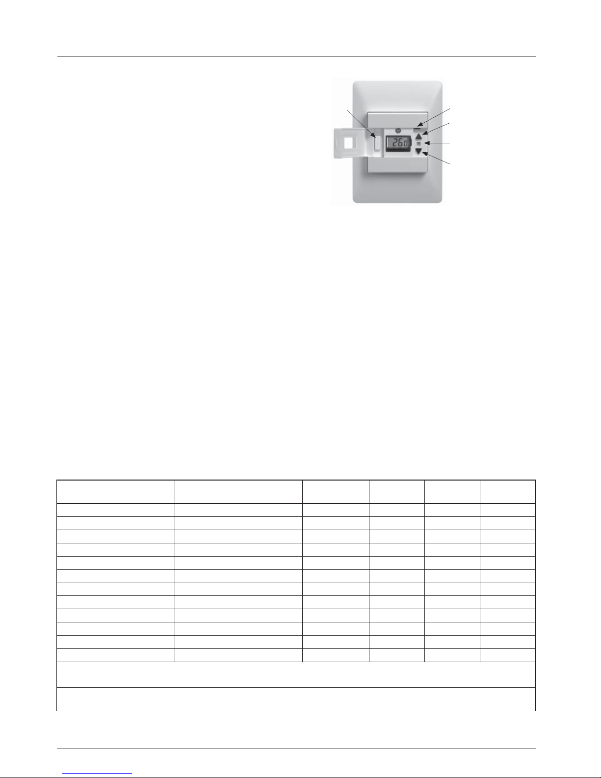
Temperature setting
Interrupter
LED
Increase temperature
Programming button (P)
Decrease temperature
The thermostat has a temperature setting range of 0-40°C.
Set the wanted temperature with the arrow buttons, the set temperature shows in the display. The thermostat will calculate the best
way to control the heating system in order to achieve the desired
temperature. If necessary, fi ne adjustment can be performed after
1 or 2 days.
Night setback
The night setback/economy temperature function is activated via
a 230 V signal from an external timer connected to terminal S.
The function is factory set to 5°C (2-8° OTD2). The LED lights green
when the economy signal is active and red when heating is active.
Frost protection
If the signal is connected via a rectifi er diode, the thermostat will
maintain a fl oor/room temperature of 5°C.
Settings
To set parameter values, press and hold the programming button
for 3 seconds. SCA Hi 40 will be shown on the display. Firstly, SCA will be displayed for 1 second, followed by Hi, and fi nally
40. The required value can then be set using the arrow buttons. To
access the next parameter, press the programming button again.
If no buttons are pressed for 30 seconds, the program returns to
the initial display.
Parameter Shown on display Factory setting
OJ standard
OTD2 -1999 OTN2 -1991 OTN2 -1999
Max. temperature SCA Hi 40 40°C (0-40°C) • • •
Min. temperature SCA Lo 0 0°C (0-40°C) • • •
Max. limit temperature FLOOR Li Hi 28 28°C (15-55°C) •
Min. limit temperature FLOOR Li Lo 15 15°C (5-30°C) •
Measure fl oor temperature FLo 24.5 •
Measured room temperature ro 21.5 •
Application APp A : Room sensor *1 • •
F : Floor sensor *2 • •
AF : Room with Limit sensor *2 •
C : Controller •
Offset oFF 0 0 (+/- 3°C) • • •
Night setback/ECO nSb 5 5°C (2-8°C) •
*1 : Only available if fl oor sensor is not installed
*2 : Only available if fl oor sensor is installed
If Controller (C) is selected under Application, the fl oor and room sensors are disconnected and heating is controlled on a scale of 0-10,
corresponding to 0-100% activated
Page 3

3
© 2010 OJ Electronics A/S
Error codes
E1 - Sensor error. Sensor is short-circuited or disconnected.
The LED is fl ashing red once.
E2 - Limit error. The temperature on the fl oor has surpassed
max. limit temperature. The thermostat switch off the heating
and the LED is fl ashing red twice.
E5 - Overheating. The temperature is too high in the termostat and
switch off the heating. The LED is fl ashing 5 times.
Type MTC2 / MTD2 with room or floor sensor English
-10
0
10
20
30
64000
38000
23300
14800
9700
Valor (ohmios)
Sensor
Temp. (°C)
BR929A08-E
Sensor table Night setback Frost protection
Environment protection/recycling
Help protect the environment by disposing of the packaging and
redundant products in a responsible manner.
Product disposal
Products marked with this symbol must not be disposed of together with household refuse but must be
delivered to a waste collection centre in accordance
with current local regulations.
Page 4

4
© 2010 OJ Electronics A/S · ® The OJ trademark is a registred trademark belonging to OJ Electronics A/S
OJ ELECTRONICS A/S
Stenager 13B · DK-6400 Sønderborg
Tel.: +45 73 12 13 14 · Fax +45 73 12 13 13
oj@oj.dk · www.oj.dk
 Loading...