

Page 1
INSTRUCTIONS
© 2014 OJ Electronics A/S
1
67303 06/14 - (LOA)
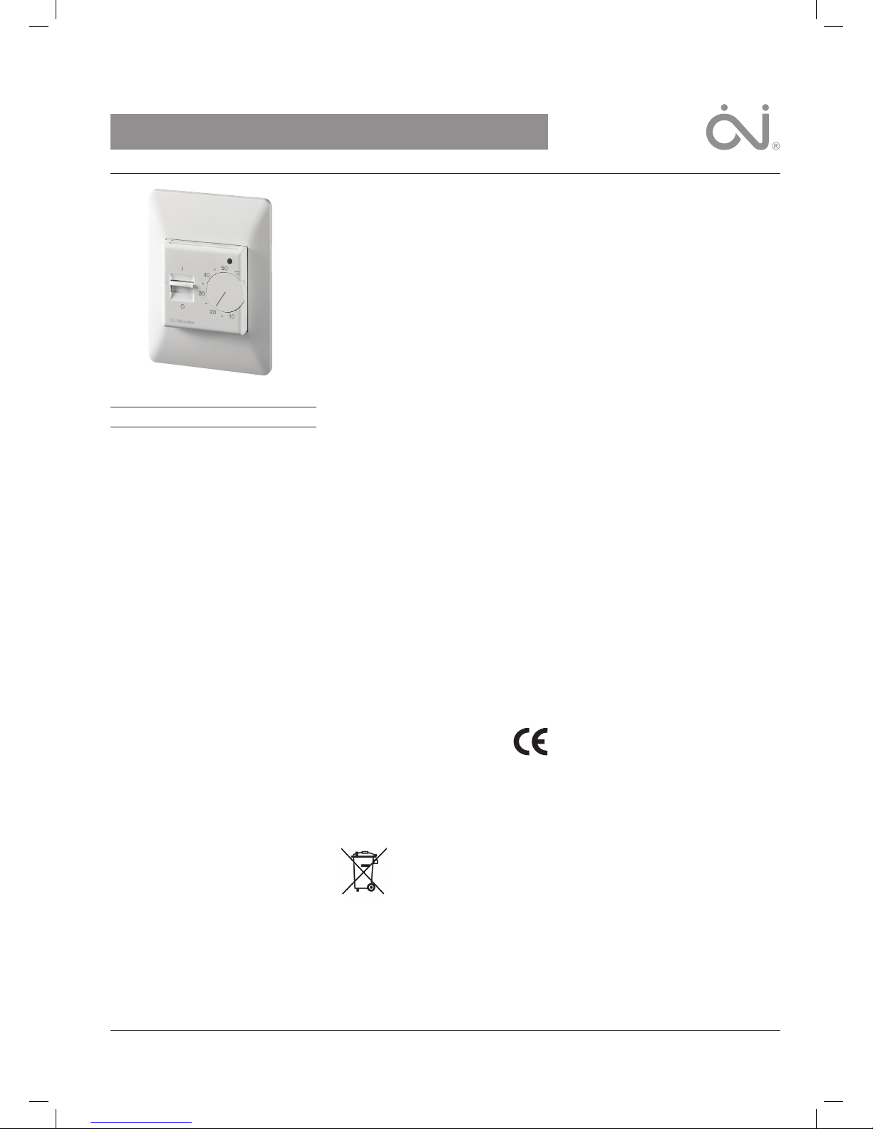
Type MTC with air sensor or floor sensor
English
MTC is an electronic heating thermostat
designed to be vertically installed in a standard
electrical wall box. Once installed, it requires no
maintenance.
An LED illuminates to indicate „call“ for heating,
this also aids in system testing. An ON/OFF interrupter on the front of the cover makes system
operation extremely simple.
PRODUCTS
Type Product
MTC-1991 with floor sensor
MTC-1999 with built-in air sensor
CLASSIFICATION
The product is a class II device (enhanced
insulation) and the product must be connected
to the following leads,
Term. 1: Phase (L) 230 V ±10%, 50/60 Hz
Term. 2: Neutral (N)
Term. 3–4: Load max. 14 A, 3.200 W
WARNING
The system may not be energized unless the
system is installed according to this instruction
and the installation meets all applicable codes.
Warranty is void if not installated according to
this instruction and proper procedure.
TECHNICAL DATA
Power supply .... 230 V AC ±10 %, 50-60 Hz
Output relay, SPST (resistive load) ...... 14 A
Built-in switch .................2 pole, 14 A
Ambient operating temperature ...... 0-50 °C
Scale limitation ......minimum and maximum
Scale range .....................10-50 °C
Temperature setback ...........not available
On/O dierential ..................0.4 °C
Enclosure ...........................IP21
Dimensions (HxWxD) .........115x84x50 mm
MOUNTING OF FLOOR SENSOR
The floor sensor is used for temperature regulation in floor surfaces. For easy replacement
the sensor can be mounted in a tube which is
placed between 2 heating cables. The tube is
ended towards the floor surface and sealed. If
required, the sensor cable can be extended up
to about 100 m with a standard installation cable. 2 leads in a multi lead cable, which is used
as supply cable for the heating cable, must not
be used. Voltage signals may occur which may
disturb the thermostat function. If a screened
cable is used, the screen must not be earthed
but must be connected to terminal 6.
PLACEMENT OF THERMOSTAT WITH
BUILT-IN AIR SENSOR
The thermostat is to be mounted on the wall
with free air circulation around it . Furthermore
it has to be placed where it is not influenced by
any other heating sources (e.g. the sun), draft
from doors or windows, or by the temperature
of an exterior wall.
ERROR DETECTION
The MTC has built-in error detection which will
de-energize the heating circuit if the sensor is
damaged or if it detects an open or shorted
sensor circuit.
CAUTION!
Disconnect all electrical power prior to installing
or servicing this unit.
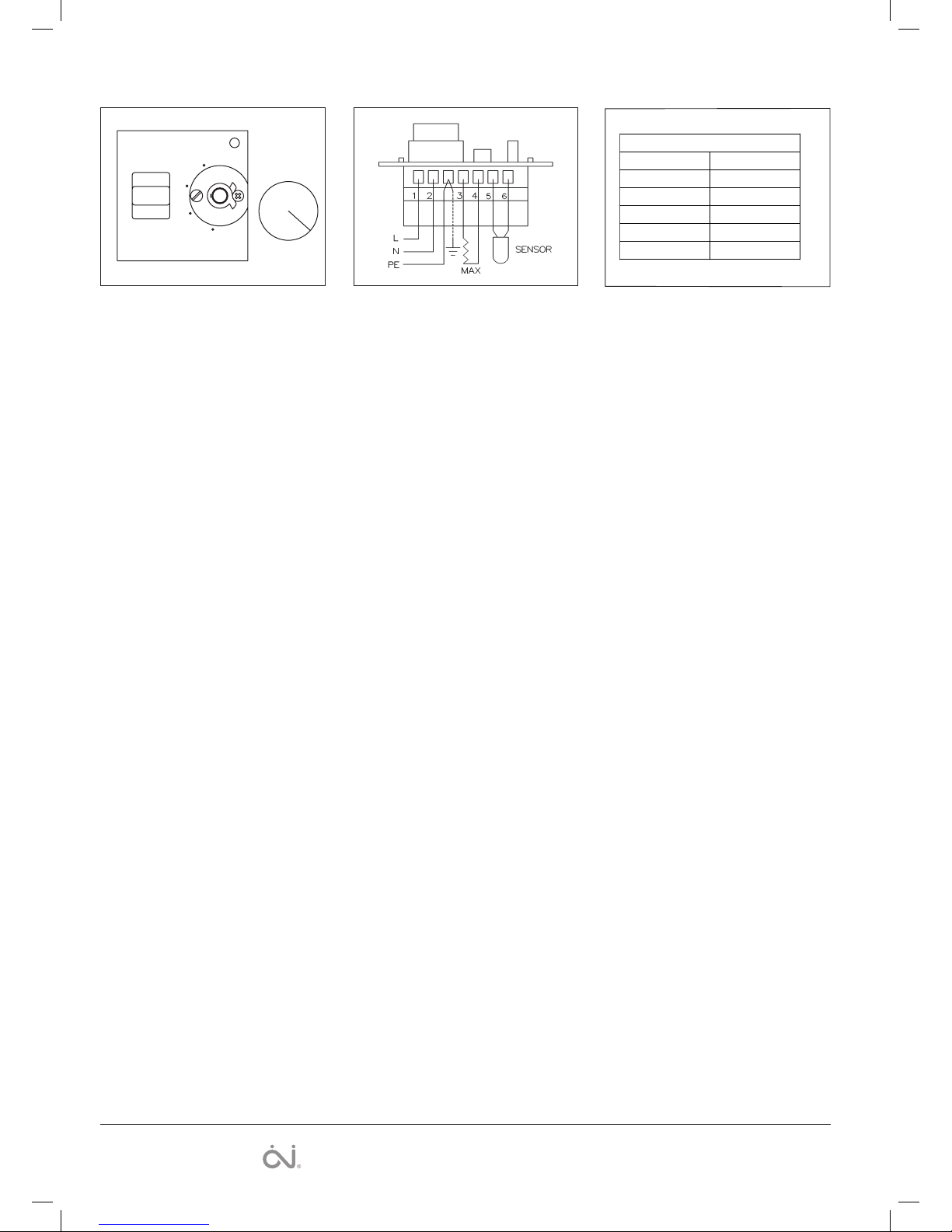
THERMOSTAT INSTALLATION (FIG. 1-2)
1. Remove thermostat knob,
noting the position (A).
2. Loosen screw to remove frame and cover (B).
3. Attach wiring from the rear of the thermostat
according to the wiring diagram.
4. The thermostat is mounted vertically in a
standard single gang electrical box. Please
note that the adapter plate is properly clipped
on the thermostat.
- re-install frame and cover
- re-install the knob in the proper position
MAXIMUM/MINIMUM TEMPERATURE
LIMITATIONS
Behind the knob there are red and blue locking
rings held in position by a screw. To set the
limitations, loosen the screw (C) and adjust the
red limit ring to the desired maximum, set the
blue ring to the desired minimum temperature,
then retighten the screw. The knob must be reinstalled exactly as it was removed.
Installation of the thermostat and adjustment of
the max and min temperature adjustment must
be done by an authorised electrician.
CE MARKING
According to the following directives:
EN 61000-6-2, EN 61000-6-3,
EN 60730-1 and EN 61730-2-9.
ENVIRONMENT AND RECYCLING
Please help us to protect the environment by
disposing of the packaging in accordance with
national regulations for waste processing.
RECYCLING OF OBSOLETE APPLIANCES
Appliances with this label must not
be disposed of with general
household waste. They must be
collected separately and disposed
of in compliance with local
regulations.
Page 2
2
The OJ trademark is a registered trademark belonging to OJ Electronics A/S · © 2014 OJ Electronics A/S
14 A
BR929A08
Sensor
Temp.(˚C) Value (ohm)
-10
0
10
20
30
64000
38000
23300
14800
9700
Fig. 2 Fig. 3
I
O
A
B
C
BR788A20
50
˚C
40
30
20
10
Fig. 1
OJ ELECTRONICS A/S
Stenager 13B · DK-6400 Sønderborg
Tel: +45 73 12 13 14 · Fax: +45 73 12 13 13
oj@ojelectronics.com · www.ojelectronics.com
BR788A20
BR788A04b
BR929A08
 Loading...