

OJ Electronics MICROLINE OTN2, MICROLINE OTD2, MICROLINE OTN2-1991, MICROLINE OTN2-1999, MICROLINE OTD2-1999 User Manual
Page 1
1
© 2010 OJ Electronics A/S
Type OTN2 / OTD2
with room or floor sensor
English .......................1
Español ......................5
Português.................9
67076A 09/10 (MBC)
© 2010 OJ Electronics A/S
U S E R M A N U A L
Contents
Introduction
MICROLINE electronic thermostat for installation in standard wall
box. The thermostat allows the required temperature to be set within the range 0-40°C. An LED indicates whether heating is active.
The thermostat is suitable for ELKO and NORWESCO systems
S-16, RS-16 and UNI-10. An extra frame is supplied with the unit.
Microline product programme
OTN2-1991 with floor sensor
OTN2-1999 with built-in room sensor
OTD2-1999 with built-in room sensor and external limitation sensor
CE marking
Applied standards
EN 61000-6-3, EN 61000-6-2, EN 60 730-1 and EN 60730-2-9.
The product may only be used if the complete installation complies
with current directives.
The thermostat must only be installed by an authorised electrician.
If the product has been damaged in any way, e.g. during transport,
it must be inspected and checked by authorised personnel before
being connected to the power supply.
The product carries a manufacturer’s warranty if installed in accordance with these instructions and applicable regulations.
Type OTN2 / OTD2 with room or floor sensor English
Technical data
Voltage .......................................................... 230 V AC ±15% 50 Hz
Max. pre-fuse ............................................................................ 16 A
Built-in circuit breaker ................................................... 2-pole, 16 A
Output relay ........................................... Make contact - SPST - NO
Output ................................................................Max. 16 A / 3600 W
Control principle .................................................................. ON/OFF
Temperature range .............................................................+0/+40°C
Dierence/hysteresis ................................................................ 0.4°C
Economy temperature ........................................... 5°C (2-8°C OTD2)
- control voltage signal ....................................................... 230 V AC
Frost protection temperature ........................................5°C absolute
- control voltage signal via rectifier diode ......................... 230 V AC
Range limits .......................................................................min./max.
Sensor fault protection .............................................................-20°C
Ambient operating temperature ............................................ 0/+40°C
Dimensions ..................................................... H/81, W/81, D/40 mm
Enclosure rating ........................................................................ IP 21
The thermostat is maintenance free.
Classifica tion
The product is a Class II appliance (with reinforced insulation) and
must be connected as follows:
Term. 1: Live (L1) 230 V ±15%, 50/60 Hz
Term. 2: Neutral (L2)
Term. 3–4: Max. load 16 A, 3600 W
Introduction ................................................................................ 1
Microline product programme ................................................. 1
CE marking................................................................................. 1
Technical data ............................................................................ 1
Sensor installation ..................................................................... 2
Installation of thermostat ........................................................ 2
Environment protection/recycling ........................................... 3
Product disposal ........................................................................ 3
Page 2
2
© 2010 OJ Electronics A/S
© 2010 OJ Electronics A/S
Type OTN2 / OTD2 with room or floor sensor English
Pollution class: 2
Pollution class 2, representative of air circulation in typical homes.
Overvoltage category: III
Pulse voltage 4 kV to IEC 60664-1.
Sensor installation
Floor sensor:
The floor sensor should be installed in standard conduit embedded
in the floor. The conduit should be sealed and positioned as close
to the floor surface as possible.
Room sensor:
The room sensor should be installed in a standard wall box or
mounted direct on the wall. Sensor cables can be extended up to a
maximum of 50 m in length using power cable. Two wires in a multiwire cable must, however, not be used if the cable is also used to
supply power to heating cables. The best result is achieved if a separate cable, installed in a separate conduit, is used for the sensor.
Installation of thermostat
Built-in or external room sensor
The thermostat or external room sensor should be mounted on a
wall in such a way as to allow free air circulation around it. It must
also be positioned so as to prevent it from being aected by direct
heat sources (e.g. the sun), draughts from doors and windows, or
outside temperature (i.e. do not mount on outer walls). MICROLINE has a built in fault circuit which switches the heating o if the
sensor is disconnected or short-circuited.
Thermostat installation
- Open cover.
- Unscrew cover and remove.
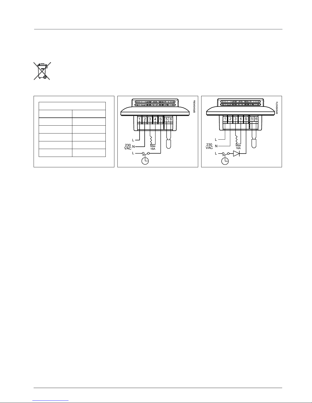
- Connect wires from rear as shown in wiring diagram.
- Mount thermostat in wall box - fit frame and cover.
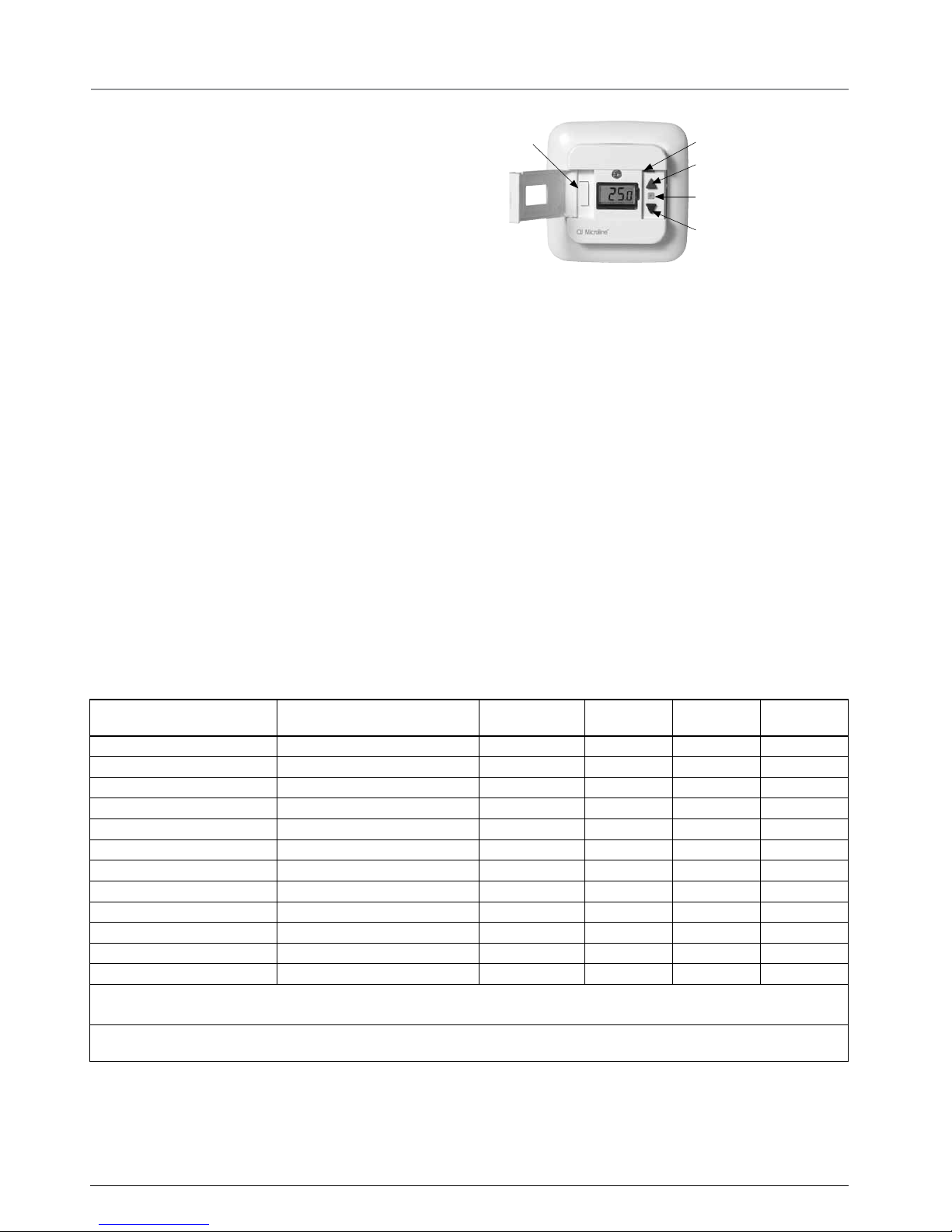
Temperature s etting
Interrupter
LED
Increase temperature
Programming button (P)
Decrease temperature
MICROLINE has a temperature setting range of 0-40°C.
Set the wanted temperature with the arrow buttons, the set temperature shows in the display. The thermostat will calculate the best
way to control the heating system in order to achieve the desired
temperature. If necessary, fine adjustment can be performed after
1 or 2 days.
Night setb ack
The night setback/economy temperature function is activated via
a 230 V signal from an external timer connected to terminal S.
The function is factory set to 5°C (2-8° OTD2). The LED lights green
when the economy signal is active and red when heating is active.
Frost protection
If the signal is connected via a rectifier diode, the thermostat will
maintain a floor/room temperature of 5°C.
Settings
To set parameter values, press and hold the programming button
for 3 seconds. SCA Hi 40 will be shown on the display. Firstly, SCA will be displayed for 1 second, followed by Hi, and finally
40. The required value can then be set using the arrow buttons. To
access the next parameter, press the programming button again.
If no buttons are pressed for 30 seconds, the program returns to
the initial display.
Parameter Shown on display Factory setting
OJ standard
OTD2 -1999 OTN2 -1991 OTN2 -1999
Max. temperature
SCA Hi 40
40°C (0-40°C) • • •
Min. temperature
SCA Lo 0
0°C (0-40°C) • • •
Max. limit temperature FLOOR
Li Hi 27
27°C (15-55°C) •
Min. limit temperature FLOOR
Li Lo 15
15°C (5-30°C) •
Measure floor temperature
FLo 24.5
•
Measured room temperature
ro 21.5
•
Application
APp A : Room sensor *1
• •
F : Floor sensor *2
• •
AF : Room with Limit sensor *2
•
C : Controller
•
Oset
oFF
0 0 (+/- 3°C) • • •
Night setback/ECO
nSb
5 5°C (2-8°C) •
*1 : Only available if floor sensor is not installed
*2 : Only available if floor sensor is installed
If Controller (C) is selected under Application, the floor and room sensors are disconnected and heating is controlled on a scale of 0-10, corresponding to 0-100% activated
Error codes
E1 - Sensor error. Sensor is short-circuited or disconnected. The LED is flashing red once.
E2 - Limit error. The temperature on the floor has surpassed max. limit temperature. The thermostat switch o the heating and the LED is fla-
shing red twice.
E5 - Overheating. The temperature is too high in the termostat and switch o the heating. The LED is flashing 5 times.
Page 3
3
© 2010 OJ Electronics A/S
Environment protection/recycling
Help protect the environment by disposing of the packaging and
redundant products in a responsible manner.
Product disposal
Products marked with this symbol must not be disposed of together with household refuse but must be
delivered to a waste collection centre in accordance
with current local regulations.
Type UCG/UDG English
OJ Electronics A/S
Stenager 13B · DK-6400 Sønderborg
Tel.: +45 73 12 13 14 · Fax +45 73 12 13 13
oj@oj.dk · www.oj.dk
-10
0
10
20
30
64000
38000
23300
14800
9700
Valor (ohmios)
Sensor
Temp. (°C)
BR929A08-E
Sensor table Night setback Frost protection
Page 4

4
OJ ELECTRONICS A/S
Stenager 13B · DK-6400 Sønderborg
Tel.: +45 73 12 13 14 · Fax +45 73 12 13 13
oj@oj.dk · www.oj.dk
The OJ trademark is a registred trademark belonging to OJ Electronics A/S · © 2010 OJ Electronics A/S
Page 5

5
© 2010 OJ Electronics A/S
Tipo OTN2 / OTD2
con sensor de temperatura
ambiente o de piso
English .......................1
Español ......................5
Português.................9
67076A 09/10 (MBC)
© 2010 OJ Electronics A/S
M A N U A L D E L U S U A R I O
Contenido
Introducción
Termostato electrónico MICROLINE para la instalación en caja mural estándar. El termostato permite ajustar la temperatura necesaria dentro de la gama de 0-40 °C. Un LED indica si la calefacción
está activa. El termostato es compatible con los sistemas ELKO y
NORWESCO S-16, RS-16 y UNI-10. Con la unidad se suministra
un bastidor adicional.
Programa de productos Microline
OTN2-1991 con sensor de piso
OTN2-1999 con sensor de temperatura ambiente integrado
OTD2-1999 con sensor de temperatura ambiente integrado y
sensor limitador externo
MARCA CE
Normas aplicadas
EN 61000-6-3, EN 61000-6-2, EN 60 730-1 y EN 60730-2-9.
El producto sólo se puede utilizar si la totalidad de la instalación
cumple con las directivas vigentes.
El termostato sólo deberá ser instalado por un electricista autorizado.
Si el producto ha sido dañado de alguna manera; por ejemplo,
durante el transporte; éste deberá ser inspeccionado y verificado
por personal autorizado antes de conectarlo a la fuente de alimentación eléctrica.
El producto está cubierto por una garantía del fabricante si se
instala de acuerdo con estas instrucciones y con las normativas
aplicables.
Tipo OTN2 / OTD2
con sensor de temperatura ambiente o de piso Español
Datos técnicos
Voltaje ........................................................... 230 V CA ±15% 50 Hz
Máx. antes del fusible ............................................................... 16 A
Disyuntor integrado ..................................................... 2 polos, 16 A
Relé de salida ........................ Contacto de activación - SPST - NO
Salida ..................................................................Máx. 16 A / 3600 W
Principio de control ................................... ENCENDIDO/APAGADO
Rango de temperatura ....................................................... +0/+40 °C
Diferencia/histéresis ................................................................ 0,4 °C
Temperatura económica ...................................... 5 °C (2-8 °C OTD2)
- señal de voltaje de control ............................................... 230 V CA
Temperatura de protección
contra el congelamiento ..............................................5 °C absoluta
- señal de voltaje de control
a través de diodo rectificador ......................................... 230 V CA
Límites de rango ................................................................mín./máx.
Protección contra fallo de sensor ............................................ -20 °C
Temperatura de funcionamiento ambiente .......................... 0/+40 °C
Dimensiones ..........................................Alt./81, An./81, Prof./40 mm
Clasificación de envolvente ...................................................... IP 21
El termostato no requiere mantenimiento.
Clasificac ión
El producto es un aparato Clase II (con aislamiento reforzado) y se
debe conectar de la manera siguiente:
Term. 1: Vivo (L1) 230 V ±15%, 50/60 Hz
Term. 2: Neutro (L2)
Term. 3–4: Carga máxima 16 A, 3600 W
Introducción ............................................................................... 5
Programa de productos Microline ........................................... 5
MARCA CE ................................................................................. 5
Datos técnicos ........................................................................... 5
Instalación del sensor ............................................................... 6
Instalación del termostato ....................................................... 6
Protección medioambiental/reciclaje ..................................... 7
Eliminación de productos ......................................................... 7
Page 6

6
© 2010 OJ Electronics A/S
© 2010 OJ Electronics A/S
Clase de c ontaminación: 2
Contaminación clase 2, representativa de la circulación del aire en
viviendas típicas.
Categoría de s obretensión: III
Voltaje de impulso 4 kV según IEC 60664-1.
Instalación del sensor
Sensor de piso:
El sensor de piso deberá instalarse en un conducto estándar
incrustado en el piso. Se recomienda sellar el conducto y colocarlo
lo más cerca posible a la superficie del piso.
Sensor de temperatura ambiente:
Se recomienda instalar el sensor de temperatura ambiente en una
caja mural estándar o instalarlo directamente en la pared. Los
cables del sensor se pueden extender hasta un máximo de 50 m de
longitud utilizando cable de alimentación eléctrica. Sin embargo, no
se deben usar dos conductores en un cable con varios conductores si el cable se utilizará también para suministrar alimentación
eléctrica a los cables de calefacción. El mejor resultado se logra
usando un cable separado para el sensor, instalado en un conducto
separado.
Instalación del termostato
Sensor ambiente incorporado o externo
El termostato o el sensor de temperatura ambiente externo deberá
instalarse en una pared de manera que permita la libre circulación
del aire alrededor del mismo. Además, se debe colocar de manera
que no lo afecten las fuentes de calor directo (como el sol), las
corrientes de aire de puertas y ventanas, o la temperatura exterior
(es decir, no se debe instalar en paredes exteriores). MICROLINE
tiene un circuito de fallo integrado que apaga la calefacción si se
desconecta o se cortocircuita el sensor.
Instalación del termostato
- Abra la cubierta.
- Desenrosque la cubierta y retírela.
- Conecte los alambres desde la parte trasera según se indica en
el diagrama de cableado.
- Instale el termostato en una caja mural. Ajuste el bastidor y la
cubierta.
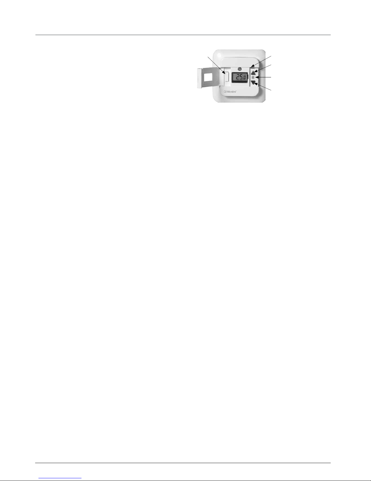
Ajuste de temperatura
Interruptor
LED
Aumentar la temperatura
Botón de programación (P)
Reducir la temperatura
MICROLINE tiene un rango de ajuste de temperatura de 0-40 °C.
Ajuste la temperatura deseada con los botones de flecha, la temperatura establecida aparece en la pantalla. El termostato calculará la
mejor manera de controlar el sistema de calefacción a fin de lograr
la temperatura deseada. Si fuese necesario, se puede realizar un
ajuste de precisión después de 1 ó 2 días.
Reducción de temperatura nocturna
La función de reducción de temperatura nocturna/económica se
activa por medio de una señal de 230 V desde un temporizador
externo conectado al terminal S.
La función ha sido ajustada en la fábrica a 5 °C (2-8 ° OTD2). El indicador LED se ilumina de color verde cuando la señal económica
está activa y de color rojo cuando la calefacción está activa.
Protección anticongelante
Si la señal está conectada por medio de un diodo rectificador, el
termostato se mantendrá a una temperatura de piso/ambiente de
5 °C.
Ajustes
Para ajustar los valores de parámetro, pulse sin soltar el botón
de programación durante 3 segundos. En la pantalla aparecerá
el mensaje SCA Hi 40. Primero aparecerá SCA durante 1
segundo, después aparecerá Hi, y finalmente 40. Entonces se
podrá ajustar el valor requerido con los botones de flecha. Para
obtener acceso al parámetro siguiente, vuelva a pulsar el botón de
programación. Si no se pulsa botón alguno durante 30 segundos,
el programa vuelve a la pantalla inicial.
Tipo OTN2 / OTD2 con sensor de temperatura ambiente o de piso Español
Page 7

7
© 2010 OJ Electronics A/S
Parámetro Aparece en pantalla Ajuste de fábrica
Estándar OJ
OTD2 -1999 OTN2 -1991 OTN2 -1999
Temperatura máx.
SCA Hi 40
40 °C (0-40 °C) • • •
Temperatura mín.
SCA Lo 0
0 °C (0-40 °C) • • •
Límite máx. de temperatura PISO
Li Hi 27
27 °C (15-55 °C) •
Límite mín. de temperatura PISO
Li Lo 15
15 °C (5-30 °C) •
Temperatura de piso medida
FLo 24.5
•
Temperatura ambiente medida
ro 21.5
•
Aplicación
APp A : Sensor de temperatura ambiente *1
• •
F : Sensor de piso *2
• •
AF : Habitación con sensor
limitador *2
•
C : Controlador
•
Compensación
oFF
0 0 (+/- 3 °C) • • •
Reducción de temperatura nocturna/ECO
nSb
5 5 °C (2-8 °C) •
*1 : Solamente está disponible si el sensor de piso no está instalado
*2 : Solamente está disponible si el sensor de piso está instalado
Si se selecciona el Controlador (C) bajo Aplicación, se desconectan los sensores de piso y de temperatura ambiente y la calefacción se controla en una escala de 0-10, que corresponde de 0- 100% activado
Códigos de error
E1 - Error de sensor. Sensor en cortocircuito o desconectado. El LED se ilumina en rojo una vez.
E2 - Error de límite. La temperatura en el piso ha sobrepasado la temperatura límite máxima. El termostato apaga la calefacción y el indicador
LED se ilumina en rojo dos veces.
E5 - Sobrecalentamiento. La temperatura es demasiado alta en el termostato y apaga la calefacción. El indicador LED centellea 5 veces.
Protección medioambiental/reciclaje
Ayude a proteger el medio ambiente desechando el material de
embalaje y los productos redundantes de manera responsable.
Eliminación de productos
Los productos marcados con este símbolo no se deben
desechar junto con los desechos domésticos, sino llevarse a una planta procesadora de residuos de acuerdo
con las normativas locales vigentes.
OJ Electronics A/S
Stenager 13B · DK-6400 Sønderborg
Tel.: +45 73 12 13 14 · Fax +45 73 12 13 13
oj@oj.dk · www.oj.dk
-10
0
10
20
30
64000
38000
23300
14800
9700
Valor (ohmios)
Sensor
Temp. (°C)
BR929A08-E
Tabla de sensor Reducción de temperatura nocturna Protección anticongelante
Tipo UCG/UDG Español
Page 8

8
OJ ELECTRONICS A/S
Stenager 13B · DK-6400 Sønderborg
Tel.: +45 73 12 13 14 · Fax +45 73 12 13 13
oj@oj.dk · www.oj.dk
La marca es una marca comercial registrada de OJ Electronics A/S · © 2010 OJ Electronics A/S
Page 9

9
© 2010 OJ Electronics A/S
Tipo OTN2 / OTD2
com sensor de ambiente ou
de pavimento
English .......................1
Español ......................5
Português.................9
67076A 09/10 (MBC)
© 2010 OJ Electronics A/S
M a n u a l d e U t i l i z a d o r
Conteúdo
Introdução
Termóstato electrónico MICROLINE para instalação em caixa
de aparelhagem simples. O termóstato permite a regulação da
temperatura desejada entre 0 e 40 °C. LED para indicação da
activação do aquecimento. O termóstato pode ser instalado em
sistemas ELKO e NORWESCO S-16, RS-16 e UNI-10. O termóstato é fornecido com um espelho extra.
Linha de produtos Microline
OTN2-1991 com sensor de pavimento
OTN2-1999 com sensor de ambiente integrado
OTD2-1999 com sensor de ambiente integrado e sensor de pavimento externo
Marca CE
Normas aplicáveis
EN 61000-6-3, EN 61000-6-2, EN 60 730-1 e EN 60730-2-9.
O produto apenas pode ser utilizado se a instalação completa
estiver de acordo com as directivas em vigor.
O termóstato deve ser instalado apenas por electricistas devidamente qualificados.
Em caso de danificação do produto, por exemplo durante o transporte, a sua inspecção e verificação deve ser efectuada por um
técnico devidamente qualificado antes da sua ligação à corrente
de alimentação.
O produto é coberto pela garantia do fabricante se instalado de
acordo com estas instruções e os regulamentos oficiais em vigor.
Tipo OTN2/OTD2 com sensor de ambiente ou de pavimento
Português
Dados técnicos
Tensão ........................................................... 230 V AC 15%, 50 Hz
Fusível de protecção (capacidade máxima) .............................. 16 A
Disjuntor integrado ....................................................... bipolar, 16 A
Relé de saída ...................................................... Fecho de contactos
– Monopolar, mono-estado
– NA (Normalmente Aberto)
Saída ................................................................ 16 A – 3600 W, máx.
Princípio de controlo ........................................................... ON/OFF
Gama de temperaturas ................................................... +0 a +40 °C
Histerese (Diferencial On/O) .................................................. 0,4 °C
Temperatura económica ...................................... 5 °C (2-8 °C OTD2)
- sinal da corrente de controlo ........................................... 230 V AC
Temperatura para protecção anti-congelação ........5 °C, absolutos
- sinal de tensão de controlo
através de díodo de rectificação ..................................... 230 V AC
Limites do alcance ............................................................mín./máx.
Protecção contra a falha do sensor ........................................ -20 °C
Temperatura ambiente de funcionamento ........................ 0 a +40 °C
Dimensões ................................................... 81 (A), 81 (L), 40 (P) mm
Classe de protecção ................................................................IP 21
O termóstato não necessita de manutenção.
Classifica ção
O produto é do tipo “isolamento duplo” (Classe II) e deve ser ligado conforme indicado a seguir:
Terminal 1: Fase (L1) 230 V AC ±15%, 50/60 Hz
Terminal 2: Neutro (L2)
Terminais 3–4: Carga máxima 16 A – 3600 W
Introdução .................................................................................. 9
Linha de produtos Microline..................................................... 9
Marca CE .................................................................................... 9
Dados técnicos .......................................................................... 9
Instalação do sensor ............................................................... 10
Instalação do termóstato ...................................................... 10
Protecção ambiental/reciclagem ........................................... 11
Eliminação final do produto ................................................... 11
Page 10
10
© 2010 OJ Electronics A/S
© 2010 OJ Electronics A/S
Tipo OTN2 / OTD2 com sensor de sala ou de pavimento Português
Classe de poluição: 2
Classe de poluição 2, representativa da circulação de ar em habitações típicas.
Categoria de s obretensão: III
Tensão de impulso de 4 kV, conforme Norma IEC 60664-1.
Instalação do sensor
Sensor de pavimento:
O sensor de pavimento deve ser instalado em conduta normalizada embebida no pavimento. A conduta deve ser devidamente
vedada e colocada o mais próximo possível da superfície do
pavimento.
Sensor de ambiente:
O sensor de ambiente deve ser instalado em caixa de aparelhagem
de parede standard ou à face na parede. Os cabos do sensor podem ter um comprimento máximo de 50 m, com cabo de alimentação. Não devem ser utilizados 2 condutores em cabos multicondutor, no caso de o cabo ser também utilizado para alimentar os
cabos de aquecimento. Para os melhores resultados na instalação,
utilizar para o sensor um cabo separado instalado numa conduta
também separada.
Instalação do termóstato
Sensor de ambiente integrado ou externo
O termóstato ou sensor de ambiente externo deve ser montado
na parede, de modo a permitir uma livre circulação de ar em seu
redor. O posicionamento deve também prevenir a acção directa
de fontes de calor (por exemplo, radiação solar), correntes de ar
de portas e janelas ou a exposição exterior (i.e., não efectuar a
montagem em paredes exteriores). O termóstato Microline está
equipado com um circuito de detecção de defeito, que desliga
o aquecimento, se o sensor for desligado ou entrar em curtocircuito.
Instalação do termóstato
- Abrir a tampa.
- Desenroscar o parafuso da tampa e retirá-la.
- Ligar os cabos na traseira, conforme indicado no diagrama de
ligações.
- Montar o termóstato na caixa de aparelhagem da parede – instalar o espelho e a tampa.
Definição da temperatura
Interruptor
LED
Aumentar temperatura
Botão de programação (P)
Diminuir temperatura
O termóstato MICROLINE pode ser regulado de 0 a 40 °C.
Definir a temperatura desejada com os botões de seta; a temperatura é indicada no visor. O termóstato calcula a melhor maneira de
controlar o sistema de aquecimento para a temperatura desejada
ser atingida. Se necessário, regular novamente o termóstato para
uma temperatura mais rigorosa, 1 ou 2 dias após a instalação.
Redução de temperatura nocturna
A função de redução da temperatura nocturna/temperatura económica é activada através de um sinal de 230 V proveniente de
um temporizador externo ligado ao terminal S.
Esta função é regulada em fábrica para 5 °C (2 a 8 °C OTD2). O
LED acende de verde, quando o sinal de temperatura económica
se encontra activado e de vermelho, quando o aquecimento se
encontra activado.
Temperatura anti-congelação
Se o sinal for ligado através de um díodo de rectificação, o termóstato mantém uma temperatura no pavimento/sala de 5 °C.
Configurações
Para configurar o termóstato, manter premido o botão de programação durante 3 segundos. O visor apresenta a indicação SCA
Hi 40. Primeiro, o visor apresenta a indicação “SCA” durante
1 segundo; depois, apresenta a indicação “Hi” e, finalmente, a
indicação “40”. O valor desejado pode então ser regulado com
os botões de seta. Para aceder ao parâmetro seguinte, premir
novamente o botão de programação. Se nenhum botão for premido durante um período de 30 segundos, o programa regressa ao
visor inicial.
Page 11

11
© 2010 OJ Electronics A/S
Tipo UCG/UDG Português
Protecção ambiental/reciclagem
Para proteger o ambiente, a eliminação final da embalagem e dos
produtos sobrantes deve ser efectuada de maneira responsável.
Eliminação final do produto
Os produtos marcados com este símbolo não devem
ser eliminados juntamente com os resíduos domésticos
mas entregues em centros recolha apropriados, de
acordo com os regulamentos oficiais em vigor.
Parâmetro Indicado no visor Regulação de fábrica
Norma OJ
OTD2 -1999 OTN2 -1991 OTN2 -1999
Temperatura máxima
SCA Hi 40
40 °C (0 a 40 °C) • • •
Temperatura mínima
SCA Lo 0
0 °C (0 a 40 °C) • • •
Temperatura limite máxima
PAVIMENTO
Li Hi 27
27 °C (15 a 55 °C) •
Temperatura limite mínima
PAVIMENTO
Li Lo 15
15 °C (5 a 30 °C) •
Medir a temperatura do
pavimento
FLo 24.5
•
Temperatura da ambiente
medida
ro 21.5
•
Aplicação
APp A : Sensor de ambiente *1
• •
F : Sensor de pavimento *2
• •
AF : Ambiente com sensorlimite *2
•
C : Controlador
•
Desvio
oFF
0 0 (+/- 3 °C) • • •
Regulação de temperatura
nocturna/económica
nSb
5 5 °C (2 a 8 °C) •
*1 : Apenas disponível, se o sensor de pavimento não estiver instalado
*2 : Apenas disponível, se o sensor de pavimento estiver instalado
Se a opção Controlador (C) for seleccionado em Aplicação (Application), os sensores de ambiente e de pavimento são desligados e o aquecimento é controlado numa escala de 0 a 10, o que corresponde uma activação de 0 a 100%
Códigos de anomalia
E1 - Erro no sensor. Sensor em curto-circuito ou desligado. LED (vermelho) pisca uma vez.
E2 - Erro de limite. A temperatura no pavimento ultrapassou o valor limite. O termóstato desliga o aquecimento e o LED pisca (vermelho) duas
vezes.
E5 - Sobreaquecimento. A temperatura é demasiado elevada no termóstato e este desliga o aquecimento. O LED (vermelho) pisca 5 vezes.
-10
0
10
20
30
64000
38000
23300
14800
9700
Valor (ohmios)
Sensor
Temp. (°C)
BR929A08-E
Tabela de regulação dos sensores Redução de temperatura nocturna Temperatura anti-congelação
OJ Electronics A/S
Stenager 13B · DK - -6400 Sonderborg – Dinamarca
Tel. +45 73 12 13 14 · Fax +45 73 12 13 13
oj@oj.dk · www.oj.dk
Page 12

12
OJ ELECTRONICS A/S
Stenager 13B · DK-6400 Sønderborg
Tel.: +45 73 12 13 14 · Fax +45 73 12 13 13
oj@oj.dk · www.oj.dk
A marca comercial OJ é uma marca registada da OJ Electronics A/S · © 2010 OJ Electronics A/S
 Loading...