

Page 1
MCS4-10 / MSD4-1999 / MSA4-10
1 234567
8910 11 12 13 14
All-in-one Thermostat
MANUAL
Thermostat ETN4-1999
67097E 04/16 (HKT)
Languages:
• Suomi, please download the user manual (file no 67306) from www.ojelectronics.com
• English, Deutsch, Русский in this manual
Contents
Introduction ................................................................................ 1
Thermostat operation .............................................................. 1
Temperature setting .................................................................. 1
Settings ...................................................................................... 1
Max. temperature .................................................................... 2
Min. temperature ..................................................................... 2
Max. limit temperature ............................................................. 2
Min. limit temperature .............................................................. 2
Limit function ........................................................................... 2
Frost protection ....................................................................... 2
Night setback / energy-saving function ................................... 2
Measured floor temperature .................................................... 2
Measured room temperature ................................................... 2
English
Application ............................................................................... 2
Scale ........................................................................................ 3
Temperature reading ................................................................ 3
Adjust oset............................................................................. 3
Control method ........................................................................ 3
PWM cycle time ....................................................................... 3
Dierential temperature ........................................................... 3
Relay function .......................................................................... 3
EN50559 .................................................................................. 3
Program version ...................................................................... 3
Child lock .................................................................................. 3
Factory settings ......................................................................... 3
Error messages ......................................................................... 3
Introduction
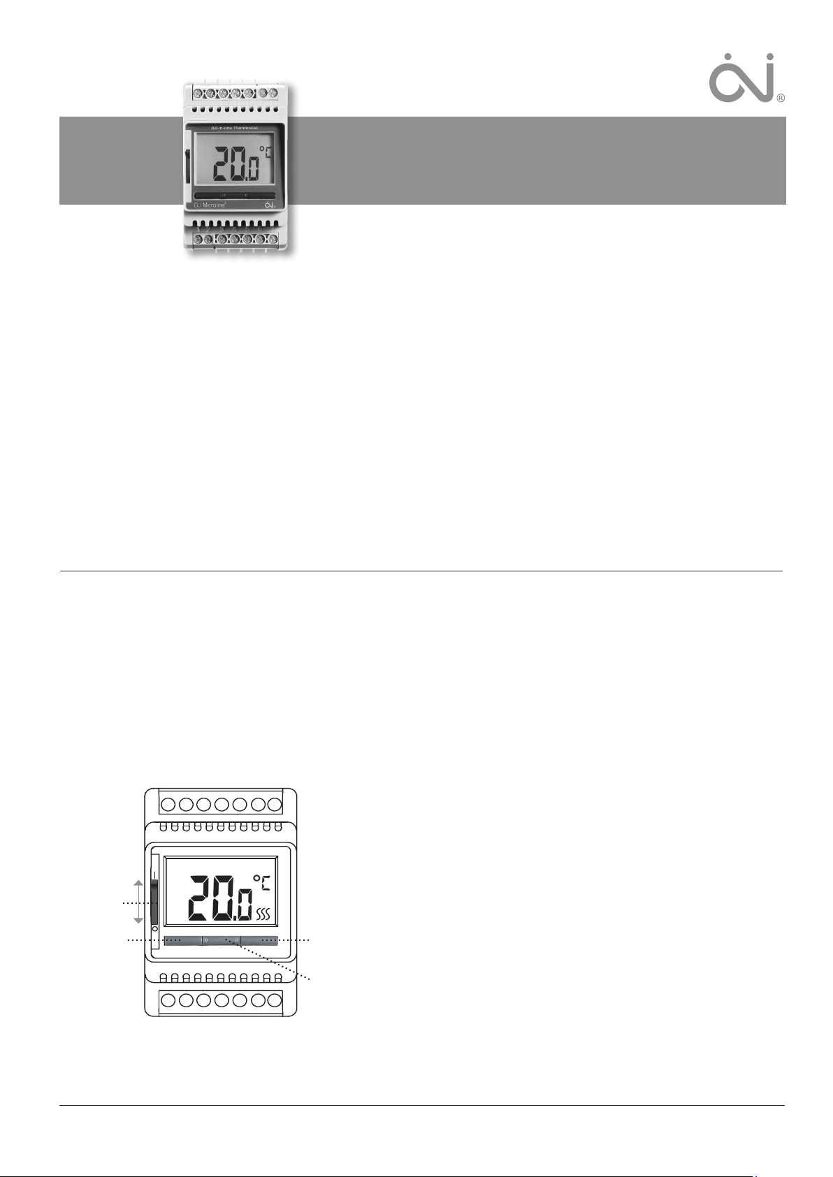
ETN4-1999 is an all-in-one thermostat for DIN-rail mounting in an
approved cabinet. It covers the needs of a variety of applications
in which maximum comfort and minimum energy consumption are
required, e.g. electric floor heating, frost protection, ice and snow
melting, cooling, etc. The thermostat allows a required temperature
to be set within the range -19.5 to +70 °C. The large backlit display
provides a clear view of status, while the three navigation buttons
allow easy menu operation.
ETN4-1999 THERMOSTAT
ON/OFF switch
Left button
Lower temperature
Right button
Raise temperature
Center button
Programming
Thermostat operation
The ON/OFF button is used to turn the thermostat o “0” or on “I”.
When the ON/OFF switch is in position “0”, the relay is deactivated.
All settings are saved.
The thermostat is easily operated using the navigation buttons.
Basic functions like temperature and thermostat settings are simple to perform. Whenever a button is pressed, the backlighting will
come on and stay lit for 30 seconds after a button is last pressed.
Temperature setting
The thermostat has a temperature setting range of -19.5 to +70 °C.
The menu allows limits to be defined for the range within temperature may be set (factory setting = 0-40 °C).
is set using the left- or right-hand button. The temperature setting
flashes on the display. Five seconds after the setting has been made,
the required temperature will be shown on the display continuously.
The required temperature
Settings
To set parameter values, press and hold the centremost button for
three seconds. SCA Hi 40 will appear on the display. Firstly,
SCA will be displayed for 1 second, followed by Hi, and finally 40.
The required value can now be set using the navigation buttons. To
access the next parameter, press the programming button again.
If no button is pressed for 30 seconds, the program returns to the
initial display.
© 2016 OJ Electronics A/S
1
Page 2
ETN4-1999 English
Frost protection
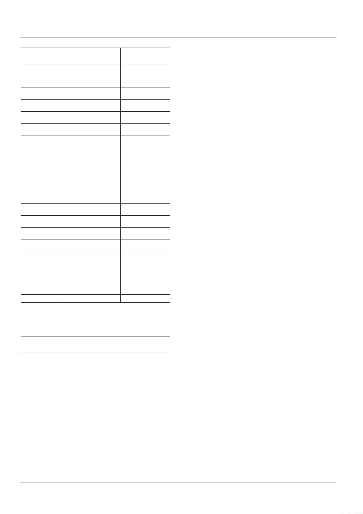
Parameter Shown on display Factory settings
Max. temperature
Min. temperature
Max. limit temperature FLOOR
Min. limit temperature FLOOR
Min. limit temperature Limit function
Frost protection
Night setback
Measured floor
temperature
Measured room
temperature
Application
Scale
Temperature reading
in start display
Adjust oset
Control method
PWM cycle time
Dierential temperature
Relay function
EN50559
Software version
*1
*2
*3
*4
*5
*6
If Regulator (C) is selected under Application, the floor and room sensors are disconnected and heating is controlled on a scale of 0-10, corresponding to 0-100 % of full
power.
*1
*1
*6
: Only available if APp AF is selected under Application.
: Only available if APp Li is selected under Application.
: Only available with external timer.
: With no or disconnected sensor, - - is shown on the display.
: Only available if PWM is ON under Control Method.
: Only available if PWM is OFF under Control Method.
SCA Hi 40
SCA Lo 0
Li Hi 28
Li Lo 15
Li Lo -19,5
*2
dEF 8.0
*3
nSb -5.0
FLo 24.5 (example)
ro 21.5 (example)
APp F (Floor sensor)
A (Room sensor)
Li (Limit function)
AF (Room sensor
C : Regulator
LCd C
dF SP
Adj 24.5 (example)
PWM On
*5
cyc 20
dIF 0.3
rEL no
PLi 0
SU 1.0
with floor temperature limits)
40°C
(0,0/+70°C)
0°C
(-19,5/+60°C)
28 °C
(-19.5/+70 °C + OFF)
15 °C
(-19.5/+70 °C + OFF)
-19,5 °C
(-19.5/+70 °C + OFF)
8 °C
(0/+10 °C)
-5 °C
(-19.5/+30 °C)
*4
*4
F : Floor
C = Celsius
(nU = numerical 0-100 %)
SP = Setpoint
(tP = actual temp.)
Actual temperature
(+/- 10 °C)
On
(OFF)
20 minutes
(10-60 min)
0.3 °C
(0.3/10 °C)
no = normally open
(nc = normally closed)
0 min (0-20 min.)
Max. temperature
The highest temperature to which the thermostat can be set.
Min. temperature
The lowest temperature to which the thermostat can be set.
Max. limit temperature
Allows the highest permissible floor temperature to be set for
wooden and other floor types when control type has been set to
room sensor with floor limit (AF).
Min. limit temperature
Allows the lowest permissible floor temperature to be set for tiled
and other floor types when control type has been set to room sensor with floor limit (AF).
Limit function
If application (APp) is set to limit (Li), the lowest temperature at
which heating is to be provided can be set.
The lowest temperature for frost protection when the function is
activated via an external signal (fig. 4 in instructions).
Example: The setpoint is 25 °C.
Frost protection = 8 °C means temp. setting = 8 °C.
Night setback / energy-saving function
The number of degrees the temperature setting is to be reduced.
The night setback setting must be preceded by a minus sign (-). Is
controlled via an external signal (fig. 3 in instructions).
Example: The setpoint is 25 °C.
Energy-saving function = -5 °C means temp. setting = 20 °C.
Energy-saving function = +3 °C means temp. setting = 28 °C.
Measured floor temperature
Displays actual floor temperature (if a floor sensor is fitted).
Measured room temperature
Displays actual room temperature.
Application
Sets thermostat function. Select the required control type. The
following alternatives exist:
Floor (F): The thermostat controls floor temperature
alone.
A floor sensor must be fitted.
Room (A): The thermostat controls room temperature
alone.
Limit (Li): Limit is an on/o function in which the
required limit is set in Limit low (”Li” ”Lo”)
after selecting the Li option under APp. When
the recorded temperature is above the temperature specified in ”Li” ”Lo”, temperature
is controlled in the usual way towards the
user-specified setpoint. If, on the other hand,
the temperature drops below that specified
in ”Li” ”Lo”, the relay cuts out and ”Lo” appears on the display.
Limit function (APp Li) should be selected if
a limit is required for when heating is permitted to be activated. Only one sensor is used
for the limit function, and this sensor must
be connected to the floor sensor input of the
thermostat.
Room/limit (AF): The thermostat controls room temperature
while respecting min. and max. limits for floor
temperature. A floor sensor must be fitted.
Regulator (C): The thermostat functions as a simple regulator
and no sensors are used. The setting is in per
cent.
”Regulator” mode in combination with
”Night setback”
If both Regulator mode (APp C) and ”Night
setback” are selected, night setback is set in
relative values while frost protection is set in
absolute values in per cent.
The setpoint specifies (in per cent) the time
the unit is to remain active in a PWM cycle,
which is usually 20 min, while setback degree
is specified as a percentage of the setpoint.
The setpoint multiplied by the setback degree
gives the activation degree.
Example: If the setpoint is set to 60 % and
night setback is set to 25 %, the activation
degree will be (0.60 x 0.25 = 0.15) = 15 %.
Graphic example:
2
© 2016 OJ Electronics A/S
Page 3

ETN4-1999 English
Local
Setpoint
in APP “C”
mode
The black area indicates the percentage cut-
Together with the light grey area, the dark grey
The light grey area is the relative amount of
The default value of setback degree ”night
nSb is inactive as default.
Frost protection ”dEF” has the specified acti-
The diagram should be read as follows:
Furthest to the left is 100 % duration of PWM,
while the vertical lines indicate successive
20 % drops in the time heating is provided
relative to 100 %.
out time determined by the setpoint.
area indicates the relative amount of operating
time when nSb has not been activated, but the
dark grey area cuts out when nSb is activated.
operating time when nSb has been activated
by the above-mentioned values.
setback” (nSb) is 30 %.
vation degree and is unaected by the setback
degree in nSb.
Setpoint
nSb Setback
nSb Activation
degree
Scale
Choose between degrees Celsius and a numerical scale. If the
numerical scale is selected, temperature is set on a scale from 0.0
to 10.0 where 0.0 corresponds to min. temperature (SCA Lo) and
10.0 corresponds to max. temperature (SCA Hi).
Temperature reading
Defines which temperature is to be shown on the start display: the
setpoint (SP) or the actual, measured temperature.
Adjust offset
If the actual temperature (measured using a thermometer) diers
from that displayed by the thermostat, the thermostat can be
adjusted to oset the dierence.
Control method
PWM or ON/OFF control can be selected. PWM is an advanced
control method which calculates the most eective and economical way to heat homes and other buildings. ON/OFF control is
traditional dierential control (e.g. 0.3 °C) for other tasks.
PWM cycle time
Allows cycle time to be set when using PWM control. At least 20
min is recommended.
Differential temperature
Allows temperature dierential to be set when using ON/OFF control. The higher the dierential temperature, the lower the number
of relay operations.
Relay function
When used for heating purposes, the relay should be in normally
open position (NO). If the thermostat is used for cooling purposes,
the relay should be turned to normally closed (NC).
EN50559
This thermostat complies with EN 50559 (VDE 0705-559) for electrical floor heating. The regulation applies to electrical floor heating,
with a maximum floor weight of 4 kN/m². To ensure that hotspots
due to unintentionally covering up the surface are avoided, the
heating function can be time-limited as per EN/DIN.
Note that this function is not applicable to other heating applications such as wall and/or ceiling heating.
If it can be foreseen in advance that unintentional covering up of a
floor might occur, then it is important to assess the correct period
of time for which the floor heating must be time-limited.
The heating can be limited using a set number between 0 - 20
minutes per hour.
Example:
If obstacles could be present that cover up the floor, then the heating might need to be limited by some number of minutes so as to
avoid hotspots in the floor.
If you want the thermostat to heat a maximum of 90 % of the time,
then the thermostat should be limited by 10 %.
Ten percent of one hour is 6 minutes.
Enter 6 min. in the EN50559 menu in order to lower the heating by
10 %.
Equation to calculate number of minutes that could be entered in
the EN50559 menu - when an average heating eect is desired:
Average wanted heating eect pr. m
1-
(
(
Floor heating element eect pr. m
Note! If the result of the equation is negative, then nothing should
be entered.
2
2
∗ 60 min.
)
)
Software version
Displays thermostat software version.
Child lock
Allows thermostats in public and other places to be locked, thus
preventing unauthorised alteration of the settings. Press and hold
the left- and right-hand buttons simultaneously for 10 seconds. A
symbol indicates that the thermostat is locked.
The child lock can be released by pressing the left- and right-hand
buttons simultaneously for 10 seconds.
Factory settings
Allows factory settings to be restored. Your personal settings will
be deleted from the thermostat.
Press and hold the centremost button for 10 seconds. The display
is switched o and then on again. Application is shown on the
display (APp F) followed by the temperature setting.
Error messages
If a fault occurs, the master/thermostat will display one of the following error codes:
Error
Fault Remedy
code
E0 Internal fault. Ther-
mostat defective.
E1 External room
sensor defective
or short-circuited
(terminals 10-11).
E2 External floor sensor
defective or shortcircuited (terminals
8-9).
Replace thermostat.
Replace sensor/sensor cable.
To continue to operate the system
without sensor, set control type to
Regulator under Application
(
APp C).
Replace sensor/sensor cable.
To continue to operate the system
without sensor, set control type to
Regulator under Application
(APp C).
© 2016 OJ Electronics A/S
3
3
Page 4
ETN4-1999 English
Error
Fault Remedy
code
E5 Internal overheating.
Thermostat shuts o
heating.
Check installations. Check that
heating cables are not overloaded
or that ambient temperature is
excessive. When internal temperature drops, the thermostat
automatically reactivates.
VDE Marking
According to the following standards,
EMC+LVD: EN 60730-1
EN 60730-2-9
OJ Electronics A/S
Stenager 13B · DK-6400 Sønderborg
Tel: +45 73 12 13 14 · Fax: +45 73 12 13 13
oj@ojelectronics.com · www.ojelectronics.com
4
The trademark is a registered trademark belonging to OJ Electronics A/S · © 2016 OJ ELECTRONICS A/S
Page 5

Inhalt
1 234567
8910 11 12 13 14
All-in-one Thermostat
MCS4-10 / MSD4-1999 / MSA4-10
Bedienungsanleitung
Thermostat ETN4-1999
Deutsch
Einleitung.................................................................................... 5
Normale Anwendung ................................................................. 5
Temperatureinstellung .............................................................. 5
Einstellungen ............................................................................. 5
Max. Temperatur ...................................................................... 6
Min. Temperatur ....................................................................... 6
Max. Grenztemperatur ............................................................. 6
Min. Grenztemperatur .............................................................. 6
Begrenzungsfunktion ............................................................... 6
Frostschutz .............................................................................. 6
Nachtabsenkung/Energiesparfunktion .................................... 6
Gemessene Bodentemperatur ................................................ 6
Gemessene Raumtemperatur .................................................. 6
Einleitung
ETN4-1999 ist ein All-in-One Thermostat für die Montage in Schaltschränken. Der Thermostat eignet sich für alle Anwendungsbereiche in denen maximaler Komfort und minimaler Energieverbrauch
gefordert sind, z. B. elektrische Bodenheizung, Frostschutz, Eisund Schneeschmelze, Kühlung u. v. m. Am Thermostat lässt sich
die gewünschte Temperatur zwischen -19,5 und +70°C einstellen.
Das große, hintergrundbeleuchtete Display gibt raschen Überblick
über den Zustand, und mit 3 Navigationstasten ist das Menü leicht
zu bedienen.
ETN4-1999-THERMOSTAT
Ein/Aus-Schalter
Linke Taste
Temperatur senken
Rechte Taste
Temperatur erhöhen
Mittlere Taste
Programmierung
Anwendung.............................................................................. 6
Skala ........................................................................................ 7
Temperaturanzeige .................................................................. 7
Kompensation ......................................................................... 7
Regelprinzip ............................................................................. 7
PBM-Zyklusdauer .................................................................... 7
Dierenztemperatur ................................................................. 7
Relaisfunktion .......................................................................... 7
EN50559 .................................................................................. 7
Softwareversion ....................................................................... 7
Kindersicherung ....................................................................... 7
Werkseinstellung ....................................................................... 7
Fehlermeldungen ....................................................................... 7
Normale Anwendung
Mit dem Ein/Aus-Schalter wird der Thermostat durch Kippen des
Schalterknopfs aus- „0“ oder eingeschaltet „I“. Bei ausgeschaltetem Thermostat „0“, ist das Relais ausgeschaltet. Alle Einstellungen
werden gespeichert.
Der Thermostat lässt sich sehr einfach mit den Navigationstasten
bedienen.
Die Basisfunktionen, wie manuelle Temperatureinstellung und
Thermostateinstellung, lassen sich sehr einfach vornehmen. Bei
erster Tastenbetätigung wird die Hintergrundbeleuchtung eingeschaltet und erlischt erst wieder 30 Sekunden nach der letzten
Aktivität.
Temperatureinstellung
Der Thermostat verfügt über einen Temperatureinstellbereich von
-19,5 bis +70°C. Mit dem Menü ist es möglich, den Einstellungsbereich auf einen passenden, gewünschten Umfang zu begrenzen
(Werkseinstellung = 0-40°C).
linken und rechten Taste einstellen. Die Temperatureinstellung wird
blinkend am Display angezeigt. 5 Sekunden nach der Einstellung
erfolgt die Anzeige dann kontinuierlich.
Die gewünschte Temperatur mit der
Einstellungen
Zur Einstellung der Parameterwerten ist die Programmiertaste in
der Mitte 3 Sekunden lang zu betätigen. Am Display wird SCA
HI 40 angezeigt. Zuerst 1 Sekunde lang SCA, danach HI, und
schließlich 40. Der gewünschte Wert kann jetzt mit den Navigationstasten eingestellt werden. Um Zugang zu den nächsten
Parameter zu erlangen, erneut die Programmiertaste betätigen.
Wird 30 Sekunden lang keine Taste betätigt, kehrt das Programm
zur Ausgangsanzeige zurück.
5
© 2016 OJ Electronics A/S
Page 6

ETN4-1999 Deutsch
Parameter Displayanzeige Werkseinstellung
Max. Temperatur
Min. Temperatur
Max. Grenztemperatur
*1
BODEN
Min. Grenztemperatur
*1
BODEN
Min. Begrenzungstemperatur
Begrenzungsfunktion
Frostschutz
Nachtabsenkung
Gemessene Bodentemperatur
Gemessene Raumtemperatur
Anwendung
Skala
Temperaturanzeige im
Startdisplay
Kompensation
Regelprinzip
PBM-Zyklusdauer
Dierenztemperatur
Relaisfunktion
EN50559
Softwareversion
*1
: Nur zugänglich bei auf APp AF eingestellter Anwendung.
*2
: Nur zugänglich bei auf APp Li eingestellter Anwendung.
*3
: Nur mit einer externen Zeitschaltuhr erhältlich.
*4
: Bei keinem oder abgeschaltetem Fühler wird am Display - - angezeigt.
*5
: Nur zugänglich bei PWM => ON als Regelprinzip.
*6
: Nur zugänglich bei PWM => OFF als Regelprinzip.
Wurde unter Anwendung Regler (C) gewählt, sind Boden- und Raumfühler abgeschaltet und die Heizung wird nach einer Skala zwischen 0-10 gesteuert, d. h von 0-100%
Leistung.
SCA Hi 40
SCA Lo 0
Li Hi 28
Li Lo 15
Li Lo -19,5
*2
dEF 8,0
*3
nSb -5,0
FLo 24,5 (Beispiel)
ro 21,5 (Beispiel)
APp F (Bodenfühler)
A (Raumfühler)
Li (Begrenzungs-
AF (Raumfühler mit
C : Regler
LCd C
dF SP
Adj 0
PWM On
*5
cyc 20
*6
dIF 0,3
rEL no
PLi 0
SU 1,0
funktion)
Grenztemperatur im Boden)
40°C
(0,0/+70°C)
0°C
(-19,5/+60°C)
28°C
(-19,5/+70°C + AUS)
15°C
(-19,5/+70°C + AUS)
-19,5°C
(-19,5/+70°C + AUS)
8°C
(0/+10°C)
-5°C
(-19,9/+30°C)
*4
*4
F : Boden
C = Celsius
(nU = Numerisch 0-100 %)
SP = Sollwert
(tP = Aktuelle Temp.)
Aktuelle Temperatur
(+/-10 °C)
On
(OFF)
20 Minuten
(10-60 min.)
0,3 °C
(0,3/10°C)
no = normally open,
normal oen
(nc = normally closed,
normal geschlossen)
0 min (0-20 min.)
Max. Temperatur
Die höchste Solltemperatur, auf die der Thermostat eingestellt
werden kann.
Min. Temperatur
Die niedrigste Solltemperatur, auf die der Thermostat eingestellt
werden kann.
Max. Grenztemperatur
Ist der Anwendungsbereich auf Raumfühler mit Grenztemperatur
im Boden (AF) angepasst, lässt sich die maximal zulässige Bodentemperatur im Holzboden u. a. m. hier einstellen.
Min. Grenztemperatur
Ist der Anwendungsbereich auf Raumfühler mit Grenztemperatur
im Boden (AF) angepasst, lässt sich die minimal zulässige Bodentemperatur im Fliesenboden u. a. m. hier einstellen.
Begrenzungsfunktion
Ist die Anwendung auf Begrenzungsfunktion (Li) eingestellt, kann
die am niedrigsten gewünschte Temperatur bei der geheizt wird
eingestellt werden.
Frostschutz
Die niedrigste Temperatur für Frostschutz, bei Aktivierung der
Funktion mittels externem Signal (Abb. 4 in der Anleitung).
Beispiel: Der Sollwert ist eingestellt auf 25°C.
Frostschutz = 8°C, entspricht einer Solltemp. = 8°C.
Nachtabsenkung/Energiesparfunktion
Anzahl Grad, um die man die Solltemperatur ändern möchte. Die
Nachtabsenkung wird mit negativem Vorzeichen (-) angegeben.
Gesteuert mittels externem Signal (Abb. 3 in der Anleitung).
Beispiel: Der Sollwert ist eingestellt auf 25°C.
Die Energiesparfunktion = -5°C, entspricht einer Solltemp. = 20°C.
Die Energiesparfunktion = +3°C, entspricht einer Solltemp. = 28°C.
Gemessene Bodentemperatur
Anzeige der aktuellen Bodentemperatur (falls montiert).
Gemessene Raumtemperatur
Anzeige der aktuellen Raumtemperatur.
Anwendung
Einstellung des Thermostats. Angewandtes Regelprinzip wählen.
Dieser Alternativen stehen zur Verfügung:
Boden (F): Der Thermostat regelt nur die Bodentemperatur.
Ein Bodenfühler muss montiert sein.
Raum (A): Der Thermostat regelt nur die Raumtemperatur.
Begrenzung (Li): Die Begrenzungsfunktion ist ein Ein/Aus-Modus,
bei dem nach Wahl der Funktion Li in der Anwendung die Grenze in Begrenzung niedrig („Li“
„Lo“) festgelegt wird. Liegt die gemessene Temperatur über der in „Li Lo“ angegebenen Temperatur, wird die Temperatur normal auf den vom
Benutzer gewählten Sollwert geregelt. Sinkt die
Temperatur hingegen unter den angegebenen „Li
Lo“-Wert, unterbricht das Relais und am Display
wird „Lo“ angezeigt.
Raum/Grenze (AF):
Der Thermostat regelt die Raumtemperatur mit min.
Regler (C): Der Thermostat wirkt als einfacher Regler, es wird
Der Sollwert gibt in Prozent die Zeit an, während
Der Sollwert multipliziert mit dem Senkungsgrad
Z. B.: Der Sollwert wird mit 60 % und der Sen-
Die Begrenzungsfunktion (APp Li) steht zur Wahl,
wenn für die Aktivierung der Heizung eine Grenze
festgelegt werden soll. Für die Begrenzungsfunktion
kann nur ein Fühler benutzt werden, der am Bodenfühlereingang des Thermostats anzuschließen ist.
und max. Grenzen für die Bodentemperatur. Ein
Bodenfühler muss montiert sein.
kein Fühler angewandt. Die Einstellung erfolgt in
Prozent.
Gleichzeitiger Betrieb mit „Reglermodus“ und
„Nachtabsenkung“.
Werden gleichzeitig Reglermodus (APp C) und
„Nachtabsenkung“ gewählt, ist die Nachtabsenkung in relativen Werten und die Frostsicherung in
absoluten Werten in Prozent einzustellen.
welcher die Einheit im PBM-Zyklus eingeschaltet
ist, typisch min. 20 Min.; der Senkungsgrad ist in
Prozent des Sollwerts angegeben.
ergibt den Einschaltgrad.
kungsgrad mit 25 % angegeben. Daraus ergibt sich
ein Einschaltgrad von (0,60 × 0,25 = 0,15) = 15 %.
6
© 2016 OJ Electronics A/S
Page 7

Absenkung
ETN4-1999 Deutsch
Grafisches Beispiel hier:
Lokale
im
APp-„C“-
Modus
Das Diagramm ist wie folgt zu verstehen:
Links entspricht 100 % des PBM-Zyklus, mit jedem
Strich nimmt die Zeit in der geheizt wird mit 20 %
von 100 % ab.
Schwarz dargestellt ist die über den Sollwert hin-
ausgehende Zeit in Prozent in der abgeschaltet ist.
Der dunkelgraue Bereich entspricht zusammen mit
dem hellgrauen der Zeit in Prozent, während der
betrieben wird wenn nSb nicht aktiviert ist. Wird
nSb aktiviert, ist auch im dunkelgrauen Bereich
abgeschaltet.
Hellgrau ist die Zeit in Prozent während der be-
trieben wird, wenn nSb mit den obenstehenden
Werten aktiviert ist.
Der Senkungsgrad „Nachtabsenkung“ (nSb) ist auf
30 % voreingestellt.
nSb ist bei Lieferung nicht aktiviert.
Die Frostsicherung „dEF“ hat den angegebenen
Einschaltgrad und wird vom Senkungsgrad in nSb
nicht beeinflusst.
Sollwert
nSb
Senkungsgrad
nSb
Einschaltgrad
Skala
Zur Wahl steht Grad Celsius und eine nummerische Skala. Bei
nummerischer Skala wird die Temperatur auf einer Skala von 0,0
bis 10,0 eingestellt, wobei 0,0 der min. Temperatur (SCA Lo) und
10,0 der max. Temperatur (SCA Hi) entspricht.
Temperaturanzeige
Die Temperatur, die bei Displaystart angezeigt werden soll; der
Sollwert (SP) oder die aktuell gemessene Temperatur (tP).
Kompensation
Entspricht die gemessene Temperatur (gemessen mit einem Thermometer) nicht dem Thermostatwert, lässt sich der Thermostat
justieren, um die Abweichung zu kompensieren.
Regelprinzip
Zur Wahl stehen PBM- oder EIN/AUS-Regelung. PBM ist ein
modernes Regelprinzip, das sich auf die ezienteste und wirtschaftlichste Nutzung ausrichtet und z. B. zur Wohnungssteuerung
angewandt wird. Die EIN/AUS-Regelung ist eine herkömmliche
Dierenzregelform (z. B. 0,3°C) für andere Anwendungen.
PBM-Zyklusdauer
Gewünschte Zyklusdauer bei Anwendung der PBM-Regelung.
Empfohlen min. 20min.
Differenztemperatur
Gewünschte Dierenztemperatur bei Anwendung der EIN/AUSRegelung. Eine Erhöhung der Dierenztemperatur bewirkt weniger
Relaisschaltungen.
Relaisfunktion
Bei Heizbedarf muss das Relais in Position Normal oen (NO) stehen. Wird die Thermostatsteuerung für Kühlung eingesetzt, ist das
Relais auf Normal geschlossen (NC) umzustellen.
EN50559
Dieser Thermostat entspricht der Norm EN 50559 (VDE 0705-559)
für elektrische Fußbodenheizung. Diese Richtlinie gilt für elektrische Fußbodenheizung mit einem maximalen Fußbodengewicht
von 4 kN/m². Um Hotspots bei unbeabsichtigter Abdeckung der
Oberfläche zu vermeiden, lässt sich die Heizfunktion gemäß EN/
DIN zeitlich begrenzen.
Bitte beachten, dass diese Funktion für andere Heizungsanwendungen, wie Wand- und/oder Deckenheizung, nicht anwendbar ist.
Ist eine unbeabsichtigte Abdeckung des Fußbodens vorhersehbar
bzw. nicht ausgeschlossen, ist die korrekte Zeitdauer einzuschätzen, während der die Fußbodenheizung zeitlich begrenzt
sein muss.
Die Heizung kann mit einer festgelegten Anzahl von 0 - 20 Minuten
pro Stunde begrenzt werden.
Beispiel:
Kann ein Abdecken des Fußbodens vorkommen, ist eine Begrenzung der Heizung über eine Anzahl Minuten erforderlich, um
Hotspots am Fußboden zu vermeiden.
Soll der Thermostat maximal 90 % der Zeit für Heizung sorgen, ist
er um 10 % zu begrenzen.
10 % einer Stunde sind 6 Minuten.
6 min. in das EN50559-Menü eingeben, um die Heizung um 10 %
zu senken.
Formel zur Kalkulation der einzugebenden Anzahl Minuten in das
EN50559-Menü – falls eine durchschnittliche Heizleistung bereitgestellt werden soll:
Durchschnittlichgeforderte Heizleistungp. m
1-
(
(
Hinweis! Ist das Ergebnis der Gleichung negativ, hat keine Eingabe
zu erfolgen.
Fußbodenheizelementleistungp. m
2
∗ 60 min.
)
)
2
Softwareversion
Anzeige der Softwareversion des Thermostats.
Kindersicherung
Es besteht die Möglichkeit den betreenden Thermostat bei Bedarf, z. B. an öentlichen oder anderen Orten, zu verriegeln, um ein
Ändern der Einstellungen zu verhinden. Dazu die linke und rechte
Taste gleichzeitig 10 Sekunden lang betätigen. Das Symbol für
lokale Verriegelung erscheint dann am Display.
Zur Aufhebung der Kindersicherung wieder die linke und rechte
Taste gleichzeitig 10 Sekunden lang betätigen.
Werkseinstellung
Ermöglicht die Rückstellung auf die Werkseinstellung. Ihre persönliche Einstellungen im Thermostat wird dabei gelöscht.
Die mittlere Taste 10 Sekunden lang betätigen. Das Display erlischt
und schaltet sich wieder ein. Die Anwendung (APp F) wird am
Display gefolgt von der Solltemperatur angezeigt.
Fehlermeldungen
Bei Auftreten eines Fehlern zeigt der Master/Thermostat einen der
folgenden Fehlercodes an:
Fehlercode Ursache Lösung
E0 Interner Fehler.
Thermostat defekt.
E1 Externer Raum-
fühler defekt oder
kurzgeschlossen
(Klemme 10-11).
Thermostat austauschen.
Fühler/Fühlerkabel austauschen. Für fortgesetzten Betrieb
ohne Fühler kann der Thermostat auf Regler unter Anwendung
APp C) eingestellt werden.
(
© 2016 OJ Electronics A/S
7
Page 8

ETN4-1999 Deutsch
Fehlercode Ursache Lösung
E2 Externer Boden-
fühler defekt oder
kurzgeschlossen
(Klemme 8-9).
E5 Interne Überhit-
zung, der Thermostat schaltet die
Heizung aus.
VDE-Kennzeichnung
Gemäß folgenden Standards:
EMC+LVD: EN 60730-1
EN 60730-2-9
Fühler/Fühlerkabel austauschen. Für fortgesetzten Betrieb
ohne Fühler kann der Thermostat auf Regler unter Anwendung
(APp C) eingestellt werden.
Installation kontrollieren. Zu
hohe Leistung der Heizkabel/zu
hohe Umgebungstemperatur.
Bei fallender interner Temperatur schaltet sich der Thermostat
automatisch wieder ein.
OJ Electronics A/S
Stenager 13B · DK-6400 Sønderborg
Tel: +45 73 12 13 14 · Fax: +45 73 12 13 13
oj@ojelectronics.com · www.ojelectronics.com
8
Die Marke ist eine eingetragene Marke der OJ Electronics A/S · © 2016 OJ Electronics A/S
Page 9

MCS4-10 / MSD4-1999 / MSA4-10
1 234567
8910 11 12 13 14
All-in-one Thermostat
Содержание
РУКОВОДСТВО
Термостат ETN4-1999
Русский
Введение ................................................................................... 9
Работа термостата .................................................................. 9
Установка температуры .......................................................... 9
Установки .................................................................................. 9
Макс. температура ................................................................ 9
Мин. температура ................................................................ 10
Макс. ограничение темп. .................................................... 10
Мин. ограничение темп. ...................................................... 10
Функция ограничения температуры ................................... 10
Защита от замерзания ........................................................ 10
Ночное понижение температуры/функция
экономии энергии …… ........................................................ 10
Измеренная темп. пола ....................................................... 10
Введение
Термостат «все в одном» ETN4-1999 устанавливается на
DIN-рейку в щитке управления. Он подходит для различных
случаев установки, где требуется максимальный комфорт при
минимальном потреблении энергии, например, электрический
обогрев пола, предотвращение замерзания помещений, для
снеготаяния и антиобледенения, охлаждения и т. п. Можно
установить необходимую температуру в диапазоне от -19.5 до
+70°C. Большой дисплей с подсветкой позволяет четко видеть
состояние термостата, а три кнопки позволяют легко перемещаться по меню и использовать функции термостата.
Измеренная темп. в помещ. ................................................ 10
Применение .......................................................................... 10
Шкала ................................................................................... 11
Индикация температуры ..................................................... 11
Калибровка .......................................................................... 11
Метод управления................................................................ 11
Время цикла ШИМ .............................................................. 11
Дифференциал темп. ......................................................... 11
Функции реле ....................................................................... 11
EN50559 ................................................................................ 11
Версия программы .............................................................. 12
Защита от детей .................................................................... 12
Заводские установки ............................................................ 12
Сообщения о неисправности............................................... 12
Работа термостата
Кнопка ВКЛ./ВЫКЛ. используется для включения или выключения термостата (“I” или “0”).
Когда кнопка ВКЛ./ВЫКЛ. находится в положении “0”, реле
дезактивировано. Все установки сохранены. Термостат легко
управляется при помощи навигационных кнопок. Основные
функции, такие, как установка температуры и настройка термостата достаточно простые.
При нажатии любой кнопки загорается подсветка дисплея и
остается включенной в течение 30 секунд
после последнего нажатия кнопки.
ТЕРМОСТАТ ETN4-1999
Переключатель
ВКЛ./ВЫКЛ.
Левая кнопка
– уменьшение
температуры
Правая кнопка
– увеличение
температуры
Центральная
кнопка - программирование
© 2016 OJ Electronics A/S
Установка температуры
Термостат имеет диапазон установки заданной температуры от
-19.5 до +70 °C. При помощи меню можно ограничить температурный диапазон в определенных пределах (заводская установка =
0-40 °C). Необходимая температура устанавливается при помощи
левой или правой кнопки. Значение заданной температуры будет
мигать на дисплее. Через 5 секунд после установки значение заданной температуры будет светиться постоянно.
Установки
Для установки значения параметров нажмите и удерживайте
центральную кнопку в течение 3-х секунд. На дисплее появится
SCA Hi 40. Первоначально в течение одной секунды появится символ SCA, затем Hi и наконец, 40. Теперь можно установить нужные значения при помощи навигационных кнопок.
Для перехода к следующему параметру нажмите кнопку программирования снова. Если в течение 30 секунд не нажимается
ни одна кнопка, дисплей вернется в исходное состояние.
9
Page 10

ETN4-1999 Русский
Параметр Индикация на дисплее
Макс. температура
Мин. температура
Макс. ограничение
темп. ПОЛА
Мин. ограничение
темп. ПОЛА
Мин. ограничение
темп. Функция ограничения температуры
Защита от замерзания
Ночное понижение
температуры
Измеренная температура пола
Измеренная температура воздуха
Применение
Шкала
Первоначальная
индикация темп. на
дисплее
Калибровка
Метод управления
Время цикла ШИМ
Дифференциал
температур
Функции реле
EN50559
Версия программы
*1
: Доступно, если в разделе «Применение» выбран APp AF.
*2
: Доступно, если в разделе «Применение» выбран APp Li.
*3
: Используется только с выносным таймером.
*4
: Индикация на дисплее - - при отсутствии или отключении датчика
*5
: Доступно, если в разделе «Метод управления» ВКЛ. ШИМ.
*6
: Доступно, если в разделе «Метод управления» ВЫКЛ. ШИМ.
Если в разделе «Применение» выбран Регулятор (C), датчики температуры пола
и воздуха отключаются и нагрев регулируется по шкале 0-10, что соответствует
мощности системы 0-100 %.
*1
*1
*2
*3
*6
SCA Hi 40
SCA Lo 0
Li Hi 28
Li Lo 15
Li Lo -19,5
dEF 8.0
nSb -5.0
FLo 24.5 (пример)
ro 21.5 (пример)
APp F (Датчик темп. пола)
A (Датчик темп. воздуха)
Li (Функция ограничения
температуры)
AF (Датчик температуры
воздуха с датчиком- ограничителем
температуры пола)
C : Регулятор
LCd C
dF SP
Adj 0
PWM On
*5
cyc 20
dIF 0.3
rEL no
PLi 0
SU 1.0
*4
*4
Заводские
установки
40 °C
(0,0/+70 °C)
0 °C
(-19.5/+60 °C)
28 °C
(-19.5/+70 °C +
ВЫКЛ)
15 °C
(-19.5/+70 °C +
ВЫКЛ)
-19,5 °C
(-19.5/+70 °C +
ВЫКЛ)
8 °C
(0/+10 °C)
-5 °C
(-19.5/+30 °C)
F : Пол
C = Цельсий
(nU = числовой
0-100 %)
SP = Заданная
темп.
(tP = Реальная
температура)
Реальная температура
(+/- 10 °C)
Вкл.
(ВЫКЛ)
20 минут
(10-60 мин.)
0.3 °C
(0.3/10 °C)
no = норм. откр.
(nc = норм.
закр.)
0 мин. (0-20 мин.)
Макс. температура
Самая высокая температура, которую можно установить на
термостате.
Мин. температура
Самая низкая температура, которую можно установить на
термостате.
Макс. ограничение температуры
Устанавливается максимальная допустимая температура пола
с целью предотвращения перегрева и повреждения деревянного или другого покрытия пола при работе термостата
с датчиком температуры воздуха и датчиком-ограничителем
температуры пола (AF).
Мин. Ограничение температуры
Устанавливается минимальная допустимая температура пола
для напольной плитки или другого покрытия пола при работе
термостата с датчиком температуры воздуха и датчиком-ограничителем температуры пола (AF).
Функция ограничения температуры
В разделе «использование» (APp) на символе (Li), можно
установить наименьшую температуру, при которой будет
осуществляться нагрев.
Защита от замерзания
Минимальная температура для предотвращения замерзания,
когда режим активируется посредством подачи внешнего
сигнала (Рис. 4 Инструкции).
Пример: заданная температура 25 °C.
Температура предотвращения замерзания = 8 °C. Это означает, что установка температуры = 8 °C.
Ночное понижение температуры / функция экономии энергии
Заданная температура должна быть уменьшена. Установка
ночного понижения температуры устанавливается со знаком (-).
Режим активируется посредством подачи внешнего сигнала
(Рис. 3 Инструкции).
Пример: заданная температура 25 °C.
Температура энергосбережения = -5 °C. Это означает, что
установка температуры = 20 °C.
Температура энергосбережения = +3 °C. Это означает, что
установка температуры = 28 °C.
Измеренная температура пола
На дисплее индикация измеренной температуры пола (если
подключен датчик температуры пола).
Измеренная температура воздуха
На дисплее индикация измеренной температуры воздуха в
помещении.
Применение
Установите режим работы термостата. Выберите необходимый
метод управления. Существуют 4 режима:
Пол (F): Термостат контролирует только темпера-
туру пола. Должен быть подключен датчик
температуры пола.
Помещение (A): Термостат контролирует только температуру
воздуха в помещении.
Ограничение (Li): Функция ограничения температуры вкл/
выкл, позволяет установить минимальное
ограничение температуры (”Li” ”Lo”)
после выбора символа Li в разделе APp.
Если температура выше, чем установлена
в разделе ”Li””Lo”, то она регулируется
обычным способом в соответствии с
установленным пользователем значением.
И наоборот, если температура опускается
ниже установленного в разделе ”Li”
”Lo”значения, то реле отключается и на
дисплее появляется символ ”Lo”.
Функцию ограничения температуры (APp
Li) необходимо устанавливать, если
необходимо ограничить температуру в тех
случаях, когда разрешена подача тепла.
Для функции ограничения температуры
используется только один датчик, который
должен быть подключен к входу датчика
температуры пола на термостате.
Помещение/ограничение
температуры пола (AF): Термостат контролирует температуру
воздуха в помещении с одновременным
10
© 2016 OJ Electronics A/S
Page 11

ETN4-1999 Русский
регулированием минимального или максимального ограничения температуры пола.
Должен быть подключен датчик температуры пола.
Регулятор (C): Термостат работает в режиме простого
регулятора и датчики температуры не используются. Установка мощности нагрева
производится в процентах.
Режим ”Регулятор” в сочетании
с режимом ”Ночного понижения
температуры”.
Если выбраны оба режима (APp C) и
”Night setback”, то ночное понижение
температуры регулируется в соответствии
с абсолютными величинами в % в
соответствии с установленным режимом
предотвращения замерзания.
Заданное значение (в %) определяет
время, во время которого устройство
остается активированным в соответствии
с циклом широтно-импульсной модуляции
и которое обычно составляет 20 минут,
в то время как уровень понижения
температуры определяется в процентном
отношении от установленного значения.
Заданное значение, умноженное на уровень
понижения температуры и дает уровень
активации.
Пример: Если заданное значение
установлено на отметке 60 % и ночное
понижение температуры установлено 25 %,
то степень активации будет (0.60 x 0.25 =
0.15) = 15 %.
Графический пример:
Локальное
понижение
температуры в
разделе APp в
режиме
регулятора “C”
Диаграмму следует читать следующим
Установка
nSb
неактивно
nSb степень
активации
образом:
Самая крайняя область слева – это 100%
продолжительность широтно-импульсной
модуляции, в то время как вертикальные
линии
Указывают последовательное 20%
понижение времени нагрева по отношению
к 100 %.
Черная область показывает время
отключения в %, по отношению к заданному
значению.
Вместе со светло серой областью черная
область показывает соответственно время
работы системы, когда режим
ночного понижения температуры (nSb)
не активирован, а темно серая область
показывает, когда режим nSb активирован.
Светло серая область показывает
соответственно время работы, когда режим
nSb активирован, как указано выше.
Уровень значения по умолчанию ”ночного
понижения температуры” (nSb) составляет
30 %.
Режим nSb не активируется по умолчанию.
Режим предотвращения замерзания ”dEF”
имеет определенную степень активации и
не зависит от степени активации
режима nSb.
Шкала
Выберите шкалу в градусах Цельсия или числовую шкалу.
Если выбрана числовая шкала, то значения температуры устанавливаются от 0.0 до 10.0, где 0.0 соответствует минимальной
температуре (SCA Lo), а 10.0 - максимальной (SCA Hi).
Индикация температуры
Определяется первоначальная индикация температуры на дисплее: заданная (SP) или реальная измеренная температура.
Калибровка
Если реальная температура (измеренная при помощи термометра) отличается от температуры на дисплее, то необходимо
внести корректировку и установить разницу температур.
Метод управления
Можно выбрать метод управления - ШИМ (широтноимпульсная модуляция) или режим ВКЛ./ВЫКЛ. ШИМ является
современным методом управления, который рассчитывает
наиболее эффективный и экономичный режим обогрева домов и других зданий. Метод ВКЛ./ВЫКЛ., используется для
других целей и является традиционным методом управления,
включающим и выключающим нагревательную систему при
перепаде температур (к примеру, 0.3 °C).
Время цикла ШИМ
Можно установить время цикла при использовании метода
управления ШИМ. Рекомендуется устанавливать, как минимум 20 минут.
Дифференциал температур
Позволяет установить дифференциал температур, активирующий подачу тепла при методе управления ВКЛ./ВЫКЛ. Чем
больше дифференциал, тем меньше число срабатываний реле.
Функции реле
При использовании термостата в режиме нагрева, контакты
реле должны быть нормально открыты (NO). Если термостат
используется в режиме охлаждения, то контакты реле должны
быть нормально закрыты (NC).
EN50559
Данный термостат предназначен для электрического обогрева
пола в соответствии с директивами EN 50559 (VDE 0705-559).
Регулирование действует для электрического обогрева пола
с максимальной нагрузкой на пол 4 кН/м². Чтобы избежать
точечного перегрева поверхности пола функцию нагрева
можно временно ограничить в соответствии с EN/DIN.
Обратите внимание, что данная функция не применима
для других способов нагрева, таких как обогрев стен и/или
потолка.
Если заранее предвидеть несанкционированный перегрев
покрытия пола, важно правильно оценить промежуток
времени, в течение которого нагрев пола должен быть
временно ограничен.
Нагрев может быть ограничен на определенное количество
минут в час в диапазоне 0 – 20 минут.
Пример:
Если на полу есть предметы, которые могут вызвать точечный
перегрев пола, нагрев на несколько минут должен быть
ограничен, чтобы избежать такого перегрева.
Если вы хотите, чтобы термостат работал для нагрева
максимум до 90% времени, нагрев должен быть ограничен
на 10%.
© 2016 OJ Electronics A/S
11
Page 12

ETN4-1999 Русский
10% в течение одного часа это 6 минут.
Чтобы снизить нагрев на 10%, введите в разделе меню
EN50559 значение 6 мин.
Уравнение для расчета количества минут для ввода в меню
EN50559 для обеспечения среднего эффекта нагрева:
1-
(
(
Эффективность нагревательного элемента обогрева пола на. м
Внимание! Если результат уравнения отрицательный – никаких
значений вводить не надо.
Желаемый средний тепловой эффект на. м
2
)
2
∗
60 мин.
)
Версия программы
Индикация на дисплее версии программного обеспечения.
Защита от детей
Позволяет исключить несанкционированное управление
термостатом детьми или при установке его в общественных
местах. Одновременно нажмите правую и левую кнопки термостата и удерживайте их в таком положении 10 сек.
На дисплее появится символ блокировки установок. Режим
блокировки может быть снят одновременным нажатием
правой и левой кнопки в течение 10 сек.
Заводские установки
Можно восстановить заводские настройки термостата. В данном случае Ваши персональные установки будут удалены.
Нажмите и удерживайте центральную кнопку термостата в
течение 10 сек. Дисплей кратковременно погаснет и загорится
снова. После этого на дисплее появится символ (APp F).
Сообщения о неисправности
При неисправности на дисплее основного/ведомого термостата появится один из следующих кодов неисправности:
Код
неисправности
E0 Внутренняя
E1 Отключение
E2 Отключение
E5 Внутренний
Неисправность Способ устранения
неисправность.
Термостат вышел
из строя.
или короткое
замыкание
выносного
датчика
температуры
воздуха (клеммы
10-11).
или короткое
замыкание
выносного
датчика
температуры пола
(клеммы 8-9).
перегрев.
Термостат
отключает нагрев.
неисправности
Замените термостат.
Замените датчик/
кабель датчика. Для
продолжения работы
системы без датчика,
переведите термостат
в режим работы в
качестве Регулятора
в разделе меню
«Применение»
(APp C).
Замените датчик/
кабель датчика. Для
продолжения работы
системы без датчика,
переведите термостат
в режим работы в
качестве Регулятора
в разделе меню
«Применение»
(APp C).
Проверьте установку.
Убедитесь, нет
ли перегрузки на
нагревательных
кабелях и или
чрезмерного их
нагрева. При падении
температуры
внутри термостата
он автоматически
продолжит работу.
МАРКИРОВКА VDE
Соответствие требованиям следующего стандарта:
EMC+LVD: EN 60730-1
EN 60730-2-9
OJ Electronics A/S
Stenager 13B · DK-6400 Sønderborg
Tel: +45 73 12 13 14 · Fax: +45 73 12 13 13
oj@ojelectronics.com · www.ojelectronics.com
12
Торговая марка зарегистрирована и принадлежит компании OJ Electronics A/S · © 2016 OJ Electronics A/S
 Loading...