

Page 1

OCS4-10 / OSD4-1999 / OSA4-10
USER MANUAL
Comfort System4TM
67023B 06/13 (MBC)
English
Contents
Introduction ...............................................................2
First time settings .....................................................2
TM
CENTRAL CONTROLLER
CS4
General operation .....................................................2
Back .......................................................................2
Exit .........................................................................2
Operation mode ........................................................2
Holiday mode ........................................................2
Comfort mode ......................................................3
Frost mode .............................................................3
Manual mode .........................................................3
Auto mode .............................................................3
Controller setup menus ...........................................3
4-event settings ........................................................3
Schedule ................................................................3
User settings .............................................................3
Time and date .......................................................3
Child lock ..............................................................3
Display settings ....................................................3
Energy monitor .....................................................4
Engineer settings ......................................................4
Oset temperature .................................................4
Adaptive function ...................................................4
Comfort System4TM Menu
Application .............................................................4
Temperature scale .................................................4
Frost temperature ..................................................4
Backlight ................................................................4
Sensor selection ....................................................4
Language ...............................................................5
Factory reset ..........................................................5
Information .............................................................5
System settings ........................................................5
Add unit .................................................................5
Remove unit ...........................................................5
Switch unit .............................................................5
Alarm relay .............................................................5
Readout .....................................................................5
Energy monitor ......................................................5
Room status ..........................................................5
Back .......................................................................5
Exit ........................................................................5
Control signal .........................................................5
Factory settings, Master ........................................6
TM
THERMOSTAT
CS4
General operation .....................................................5
Wireless signal strength ..........................................5
16:31
Tue
00: Hall
Manual temperature setting ....................................6
Settings .....................................................................6
Max. temperature ..................................................6
Min. temperature ...................................................6
Max. limit temperature ...........................................6
Min. limit temperature ............................................6
Measured floor temperature ..................................6
Measured room temperature .................................6
Application.............................................................6
Oset .....................................................................7
Backlight ................................................................7
Address readout ....................................................7
Repeater function ..................................................7
Child lock (local) .......................................................7
Factory reset .............................................................7
TM
PANEL HEATER CONTROLLER
CS4
General operation .....................................................7
LED readouts ............................................................7
Factory setting .......................................................7
COMFORT System4
Error messages ........................................................7
System factory settings ...........................................8
Preset schedule .....................................................8
TM
, GENERAL
21.0°C
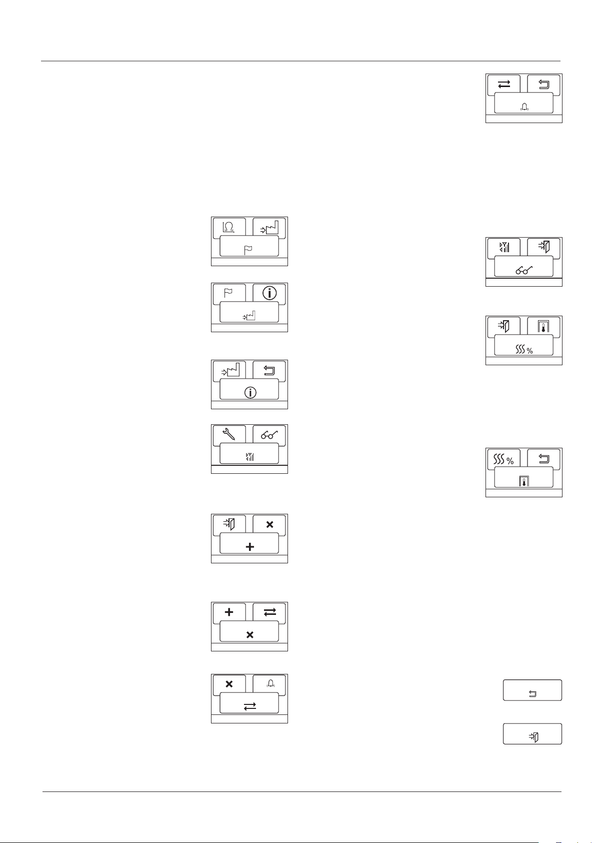
List Menu Mode
List Menu Mode
4-event settings
User settings Engineer settings System settings
Time and date
Display settings
Energy monitor
Back
Offset temp. Energy monitor
Adaptive function
Application
Temp scale
Backlight
Language
Factory reset
Information
Back
Exit
Add unit
Remove unitChild lock
Switch unit
Back
ExitExit Sensor
Readout Exit
Room status
Back
Exit BackAlarm relay
Holiday
Comfort
Frost
Manual
© 2013 OJ Electronics A/S
1
Page 2

Comfort System4TM English
Introduction
Comfort System4™ is a complete control system for multi-room,
electric heating systems consisting of up to 16 rooms. The system
consists of a Central Controller with Thermostats, Panel Heater
Controller and an Ethernet Gateway. The wireless Central Controller
and Thermostat with room and/or floor sensor ensures maximum
comfort and minimum energy costs.
The Central Controller is a central unit for controlling and monitoring up to 16 rooms. Animated menu navigation ensures easy setup,
monitoring of energy consumption and selection of comfort mode or
holiday mode.
The Central Controller has 5 built-in schedules. For each day of the
week, individual temperatures can be set for 4 dierent periods,
called events, all of which can be adjusted to suit your needs. Lowering the temperature when the home is unoccupied reduces energy
costs without reducing comfort.
Furthermore, the Central Controller features an adaptive function
that automatically adjusts heating period start times to ensure that
the required temperature is reached at the required time. After 3
days the adaptive function has learned when the heating must be
switched on.
Gateway is a new possibility for viewing and controlling Master functions from a distance. With a PC, tablet or smartphone, you can gain
access to Master functions via Gateway and the Internet. Among
other things, this gives you the opportunity to: - turn on the heating
in your summer cottage before you arrive; - turn down the temperature at home if you decide to prolong your holiday; or simply - make
small alterations to the settings if you change your daily routine.
FIRST TIME SETTINGS
Central Controller
The first time you switch the power interrupter to ON “I”, language,
time and date must be set. The menu will automatically guide you
through the process.
• Chooseyourlanguagewiththeupanddownbuttonsandconrm
with OK.
• SettheactualhourandpresstheOK button. Then set the min-
utes. Press OK.
• Settheactualdate:year,monthandday.Conrmthesettings
with the OK button.
• Choosetheroomorzonetowhichthecontrolleristobeallotted.
• Youarenowgiventheopportunityofconnectingthewireless
thermostats. Confirm with OK.
Connecting Thermostats
Before connecting the thermostats it is a good idea to note the
zone/roomforthevariousthermostatssoastofacilitatesetup,see
table at back of the manual.
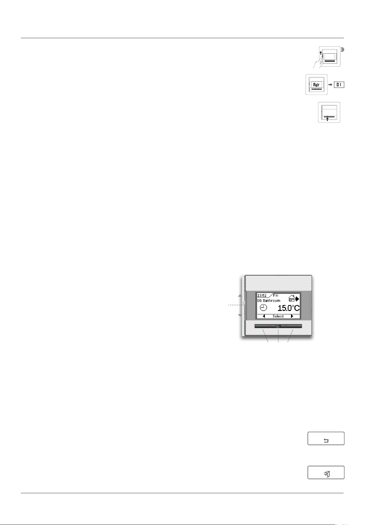
• Switch on the power of the first thermostat/panel heater controller. For the next 120 seconds,
the unit will transmit a unique signal to the controller. The thermostat will display its assigned
address and the signal strength. The controller
will display the same address.
• Switch on the power of the next thermostat/
Panel heater controller to be connected. Repeat
the procedure for all other thermostats/ Panel
heater controller.
• The units connected can now be grouped into
anareanameorzonenumberonthecontroller.Upto5area
names can be chosen.
Press OK for the chosen address and use the navigation buttons to select a suitable group.
Press Exit to complete the setup and the controller will show the
initial display.
• Comfort System4 is now ready for use and will control your
heating system in accordance with the pre-programmed 4-event
schedule, see Factory settings.
• Remember to note your settings for each thermostat/relay
point in the table on the back page.
NOTE: Control type is factory set to Room/limit. Control type
can be changed in Engineer settings/Application (page 4).
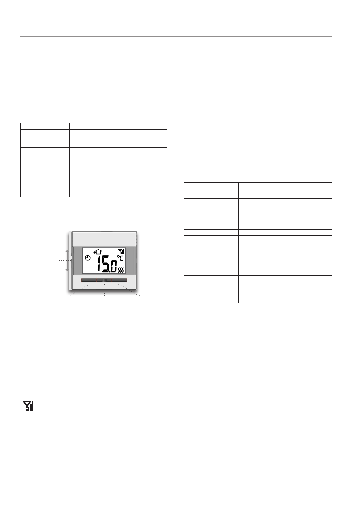
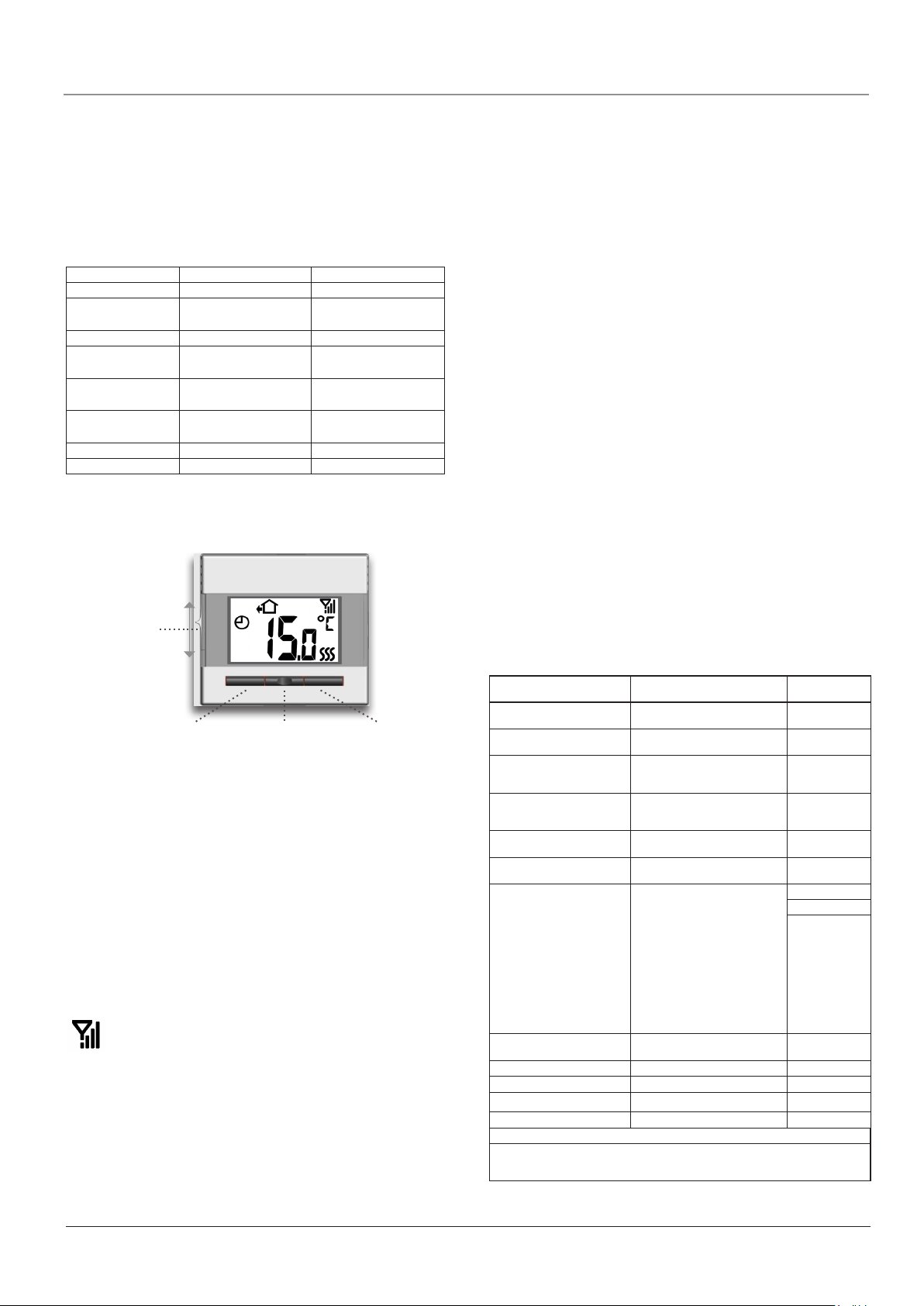
CS4TM CENTRAL CONTROLLER
Power interrupter
Navigation buttons
General operation
The interrupter button allows you to turn the controller on “I” and o
“0” by sliding the button up and down. When the Central Controller
is switched o “0”, the relay disengages. All settings, including time
and date, will be remembered.
The Central Controller is intuitively operated using the navigation
buttons.
The function of each button is indicated above the button on the
display.
Back
Various menus and submenus contain a Back
option.
UseBack to return to the previous step.
Exit
Returns to the initial display.
Back
Exit
Select room
The initial display allows you to select the room for which you want
the actual set temperature and event mode to be displayed.
Usetheleftandrightarrowbuttonstoselectthedesiredroom.
Operation mode
The Central Controller features 5 dierent types of temperature control. Press Select, then Mode:
Holiday mode
Select Holiday if you want to lower the temperature in all rooms for a specific period to
save energy, e.g. if the house is uninhabited
for a period of time.
•PressOK for Holiday, select the stop time
and date, press OK. Select the holiday temperature and confirm
with OK.
The comfort system is now in Holiday mode and a suitcase is
displayed. When the specified date and time is reached, the Central
Controller will automatically revert to Auto mode.
Holiday
OK
2
© 2013 OJ Electronics A/S
Page 3

Comfort System4TM English
Comfort mode
Select Comfort to set a temporary comfort temperature
(so-called party mode) for a single room or all rooms.
• PressComfort, confirm with OK and select the room. The com-
fort temperature becomes the highest temperature for the 4-event
plan for the day concerned. Then enter the required duration of
comfort mode: 1-8 hours.
When the period has elapsed, the Central Controller will automatically revert to Auto mode.
Frost mode
Select Frost to maintain a minimum temperature for frost protection. The comfort system
maintains a minimum temperature of 10°C
Frost
(factory setting).
• PressFrost, confirm with OK and the frost
OK
symbol will be displayed.
Manual mode
Select Manual to override the pro-
grammed4-eventscheduleinazoneby
setting a required temperature manually.
Manual
• PressManual, confirm with OK and
OK
choose the required temperature.
Auto mode
Select Auto if you want the temperature to be controlled automatically via the 4-event schedule for all rooms. The clock will be
displayed.
Please note: Auto mode can only be selected when the controller is
in one of the other modes.
Controller setup menus
The menu allows you to select the following options:
4-event settings
Allows temperature to be controlled automatically in accordance to
aprogramofyourchoice.Foreachofthe5zones,youcanselect
temperature settings for 4 dierent events during the day:
program. Press OK and set the start time for the event concerned.
Confirm with OK. Set the temperatures for this event, first room
temperature then floor temperature, and confirm with OK.
5. After setting the required events, select Back in the menu to make
changesinotherzonesorExit to return to the initial display.
Time
Min
06:00
07:00
OK
Max
08:00
Temp
5.0°C 25°C
OK
40.0°C
Schedule
Foreveryzone,the4-eventsettingsfollowaspecicschedule.
Here, you can choose the type of weekly 4-event schedule required.
5:2 : Monday to Friday with 4 events and Saturday to Sunday with 2
events. This is the factory default.
Typically used if you work from Monday to Friday.
6:1 : Monday to Saturday with 4 events and Sunday with 2 events.
Typically used if you work from Monday to Saturday.
7:0 : Monday to Sunday with 4 individual events. Allows you to
choose individual programs for each of the seven days of
week.
Select the required 4-event schedule and confirm with OK.
User settings
In the user settings menu you can change the
following items:
• Timeanddate
• Childlock
• Displaysettings
• Energymonitor
Time and date
Press OK and set the actual time in hours and
minutes.
The date will then be displayed. Set the date
and confirm with OK.
User settings
OK
Time and date
OK
Morning
Daytime
Evening
Night
Eachzoneispre-programmedwitha4-event
schedule for easy and economic heating
control, see Preset schedule under Fac-
4-event settings
tory settings. The schedule can be easily
changed in the following way:
OK
1. Press Select and then Menu to activate the 4-event settings
display. Confirm with OK.
2.Selectthezoneforwhichyouwishtomakechanges.PressOK. If
youwanttochangethescheduleforthezoneconcerned,select
Schedule in the menu and confirm with OK. The factory default is
5:2, see following section: Schedule.
3.UsetheUporDownbuttontochoosethedaysforwhichyou
want to change the settings: Mon-Fri or Sat-Sun for 5:2; MonSat or Sun for 6:1; or Mon-Sun for 7:0. Press OK.
4. Now select the time and temperature for the chosen event in the
Child lock
Allows you to lock the comfort system settings, including all thermostats, e.g. in public
or other places where you do not want the
settings changed. There are four alternative
child lock settings:
Central : Locks only the controller.
Normal : Locks all units, including the controller. Individual thermo-
stats can be unlocked locally.
Full : Locks all units, including the controller. Individual thermo-
stats can only be unlocked from the controller.
O : Disables the child lock settings.
Confirm your choice with OK. The lock symbol will be shown on the
display.
The child lock can only be unlocked on the comfort system controller by simultaneously pressing both the left and right buttons for 8
seconds.
Child lock
OK
Display settings
Allows you to select what is shown on the
initial display.
Temp -
-Set temp: Shows the current temperature
setting
Display settings
OK
© 2013 OJ Electronics A/S
3
Page 4

Comfort System4TM English
-Room: Shows the actual room temperature
-Floor: Shows the actual floor temperature
Scr. saver: Switches o the display after 60 seconds if no button
is pressed. Any subsequent press of a button reactivates the display. The controller remains active and
runs the selected program.
Idle screen: When Exit is pressed or there has been no activity for
30 seconds, the Central Controller reverts to the initial
display. There are 3 dierent display modes:
Single: Single mode is the standard initial display
(the factory setting).
Auto: Standard initial display with automatic switching between the current status of all connected room
thermostats.
Simple : Simple mode for easy mode shifting. The
controller will show the initial display in one of the three
modes: Holiday, Comfort or Frost. To enter the menu,
select Back and press OK.
Press the OK button to select or deselect the display options. Then
select Exit in the menu to return to the initial display and view your
chosen settings.
Energy monitor
To view the true cost of the energy consumed, select the actual currency and cost
per unit.
Currency: Press OK and choose the required currency.
Confirm with OK.
Cost/unit: Press OK and set the actual cost of electricity.
The cost must be entered per kWh. Press OK.
Leave the menu by pressing Exit.
To display actual energy consumption and to specify the load for
each thermostat, see Readout.
Energy monitor
OK
Engineer settings
The Engineer settings menu contains the
following options:
• Osettemperature
• Adaptivefunction
• Application
• Temperaturescale
• Backlight
• Sensorselection
• Language
• Factoryreset
• Information
Offset temperature
If the actual temperature (measured using
a thermometer) does not correspond to the
thermostat value shown on the controller, the
thermostat can be adjusted by osetting the
temperature.
Press OK and enter the measured temperature value. Confirm with
OK.
Adaptive function
Ensures that the required temperature has
already been reached when you get up in the
morning or come home from work. After just
a few days, the adaptive function will have
automatically calculated when the heating
Engineer settings
OK
Offset temp.
Adaptive function
OK
OK
must be turned on. The adaptive function applies for all units connected to the system. Press OK and set the function.
Press OK and set the function to On. Confirm with OK.
Application
Set the type of control to be used by the
Central Controller.
There are 4 options:
Floor: The Central Controller controls
floor temperature only. A floor sensor must be connected.
Room: The Central Controller controls room temperature
only.
Room/limit: The Central Controller controls room temperature with
min. and max. limits for floor temperature. A floor sensor must be connected.
Regulator: The Central Controller functions as a simple regulator
and no sensors are used. The setting is a percentage.
Temperature regulation can be achieved via the op-
tionintheUsersettingsmenu:
NOTE: Setback temperature unavailable.
Press OK and select the required application. Confirm with OK.
Application
Regulator.
OK
Temperature scale
Allows you to set the temperature range within which the Central Controller can be set. It is
then only possible to set a temperature within
this range in auto, comfort and manual mode.
Press OK to highlight Mintemperature.UsetheUporDownbutton
to select the minimum permissible temperature. Press OK and then
select the maximum permissible temperature. Confirm the settings
with OK.
Temp scale
OK
Frost temperature
The required temperature in frost protection
mode. Both room and floor temperature can
be set.
Press OK and set the required room tem-
peratureusingtheUporDownbutton.Press
OK and set the required floor temperature. Confirm the settings by
pressing OK.
Frosttemp.
OK
Backlight
There are three settings for the display backlighting:
• Auto: Backlighting is activated whenever a
key is pressed and goes out automatically
30 seconds after the last key is pressed.
• On heat: Backlighting comes on when heating is called for by the
thermostat.
• Const on: Backlighting is constantly on.
Select the required backlighting setting and confirm with OK.
Backlight
OK
Sensor selection
Floor sensors of types other than that supplied by OJ Electronics (12 kΩ/ 25°C) can
be selected in this menu. The controller is
preprogrammed for 4 other types:
Sensor 2 kΩ
Sensor 10 kΩ
Sensor 15 kΩ
Sensor 33 kΩ
Select the installed sensor with the arrow buttons, then confirm
with OK. The resistance characteristics of the sensor at 15 °C,
20 °C, 25 °C and 30 °C are now displayed.
Sensor
OK
4
© 2013 OJ Electronics A/S
Page 5
Comfort System4TM English
If the installed sensor does not have the same characteristic as
that shown in the display, change the values for the 4 listed temperatures using the arrow buttons.
Confirm with OK to switch to the next resistance characteristic.
Select Information with the arrow buttons, then confirm with OK.
The display now shows the resistance characteristic of the selected
sensor. Then confirm with OK. The new sensor values are now
stored in the controller.
Note: If an incorrect sensor is selected, there is a risk that the thermostat will not be able to maintain the required temperatures, and
damage to the floor construction or covering may therefore occur.
Language
Allows the language used on the display to be
changed.
Press OK and select the required language.
Confirm with OK.
Language
OK
Factory reset
Allowsfactorysettingstoberestored.Your
personal settings will be lost, see System
factory settings.
Press OK and choose Reset in the menu.
Confirm with OK.
Factory reset
OK
Information
Displays the thermostat software version.
Information
OK
System settings
The System settings menu contains the following options:
• Addunit
• Removeunit
• Switchunit
• Alarmrelay
Add unit
To add a new thermostat or relay point to the
comfort system, select Add unit and press
OK. The controller now enters "listening
mode".
For details on connecting the Thermostat/Panel Heater Controller,
see Connecting thermostats under First time settings.
Remove unit
To remove a Thermostat or Panel Heater Controller from the Comfort System, press OK.
Select the unit you want to remove and press
OK. Confirm with OK.
Switch unit
If a unit has been set up in the wrong group or
zone,youcanchangethegroup/zone.
Press OK, select the thermostat/Panel Heater
Controller concerned and press OK. Now
selecttherequiredzone.
Confirm with OK.
System settings
OK
Remove unit
Switch unit
Add unit
OK
OK
OK
Alarm relay
The central controller can be used as an alarm
relay for external signals from the output terminals. The alarm relay can be set as follows:
Sensor Err.: The alarm relay is activated
by sensor faults on one or more of the connected
thermostats.
Overheat: The alarm relay is activated by sensor faults or
overheating of units.
Communication: The alarm relay is activated by sensor faults, over-
heating of units or wireless communication faults.
O : The alarm relay function is switched o, and the
output terminals are used to control an underfloor
heating cable.
Alarm relay
OK
Readout
The Central Controller features readouts of
energy consumption and status for each connected room.
• Energymonitor
• Roomstatus
Energy monitor
Displays energy consumption for the past 2,
30 or 365 days.
Press OK and select the room you want to
view. Press OK for the chosen period. The
value in percent (%) shows the relative amount of time the heating
has been on. The following figure is the cost for the selected period.
To ensure correct calculation, check the settings for Load.
Load: Press OK and enter the connected heating power.
The value must be in watt (W). Press OK.
Leave the menu by pressing Exit.
Room status
Displaystheactualstatusforeachroom/zone.
Press OK for the chosen room thermostat.
Signal strength is displayed in the top righthand corner, with up to 4 bars at full strength.
Room: The actual room temperature in degrees.
Floor: The actual floor temperature in degrees
(if floor or limit control is selected).
Application: The application for the actual thermostat.
Operating hours: The number of hours the Central Controller has
been switched on.
ID button:
Press ID button to identify the selected Thermostat/Panel Heater
Controller. The selected unit will be identified by its ID number in the
upper left of the display in one of the following ways:
Thermostat: Display flashes the ID number.
Panel Heater: LED flashes as many times as the ID number.
The process lasts approx. 10 seconds before the unit returns to
normal mode.
Back
Various menus and submenus contain a Back
option.
UseBack to return to the previous step.
Exit
Returns to the initial display.
Readout
OK
Energy monitor
OK
Room status
OK
Back
Exit
Control signal
OCS4 is equipped with a control signal input, the terminal for
© 2013 OJ Electronics A/S
5
Page 6
Comfort System4TM English
which is marked S. By means of an external signal, the thermostat
can be controlled in three dierent modes:
•Setback: In setback mode, the thermostat controls the tempera-
ture according to the lowest programmed setting in the 4-event
schedule for floor and room temperature respectively.
•Frost protection: In frost protection mode, the thermostat
controls room temperature according to the value set under:
Engineer settings/Frost temperature.
•O: Switches the thermostat to O.
Factory settings, Master
Child lock - Room
Display settings Temperature (Temp)
Energy monitor - Currency
- Price/unit
Adaptive function On
Application Room/floor (Room/limit)
Temperature scale - Min.
- Max
Frost - Room
- Floor
Norwegian kroner (NOK)
1.23
0.0
40.0
10.0
10.0
Backlight Auto
Sensor Factory
CS4TM THERMOSTAT
Power interrupter
Left button Middle button Right button
Decrease temperature Programming Increase temperature
Manual temperature setting
The thermostat has a temperature setting range of 0-40°C. This
function allows you to override the 4-event program for the actual
event. The manual setting will apply until the next programmed
event.
Set the required temperature using the left and right buttons. The
temperature setting will flash on the display. 5 seconds later, the
temperature setting is shown constantly on the display together with
a hand symbol.
To cancel manual operation, press the middle button once and
the thermostat will revert to the automatic 4-event program on the
system controller.
Settings
To set parameter values, press and hold the middle button for 3
seconds. SCA Hi 40 will be shown on the display. Firstly, SCA
will be displayed for 1 second, followed by Hi and finally 40. The required value can then be set using the arrow buttons. To access the
next parameter, press the programming button again. If no buttons
are pressed for 30 seconds, the program returns to the initial display.
Parameter Shown on display Factory setting
Max. temperature
Min. temperature
Max. limit temperature FLOOR
Min. limit temperature FLOOR
Measured floor temperature
Measured room temperature
Application
Oset
Backlight
Address readout
Repeater function
Software version
*1 : Requires that a floor sensor is installed
SCA Hi 40
SCA Lo 0
Li Hi 28
Li Lo 15
FLo 24.5
ro 21.5
APp F (Floor sensor) *1
A (Room sensor)
AF (Room sensor with
floor limit) *1
C : Regulator
OFF 0
LHt OFF
Adr 05
rEp OFF
SU 1.0
40°C
(0-40°C)
0°C
(0-40°C)
28°C
(0-40°C + OFF)
15°C
(0-40°C + OFF)
F : Floor
0
(+/- 8°C)
OFF
OFF
General operation
The interrupter button allows you to turn the thermostat on “I” and
o “0” by sliding the button up and down. When the thermostat is
switched o “0”, the relay disengages. All settings will, however, be
remembered.
The thermostat is intuitively operated using the navigation buttons.
Basic functions such as manual temperature setting and thermostat
setup can easily be performed. Other functions such as 4-event
settings, energy readouts, etc. can be performed from the Central
Controller.
Wireless signal strength
The thermostat has a built-in signal strength monitor, which
transmits the actual signal strength to the controller. The
aerial symbol consists of 4 bars at full signal strength, 3 bars
at medium, 2 bars at low and 1 bar at very low signal strength.
If the thermostat is installed far from the controller or there are signal
absorbing materials in the building, it may be necessary to connect
a repeater, see Settings - Repeater function.
If no aerial symbol is shown on the display, wireless connection to
the Central Controller has been lost. Go to System settings / Add
unit on the Central Controller to reconnect the thermostat.
6
© 2013 OJ Electronics A/S
If Regulator (C) is selected under Application, the floor and room sensors are disconnected and the heating is controlled on a scale of 0-10, corresponding to 0-100%
activated.
Max. temperature
The highest temperature to which the thermostat can be adjusted.
Min. temperature
The lowest temperature to which the thermostat can be adjusted.
Max. limit temperature
If a limit/floor sensor is connected to the thermostat, the highest
floor temperature allowed for wooden or other floor types can be
set here.
Min. limit temperature
If a limit/floor sensor is connected to the thermostat, the lowest
floor temperature allowed for tiled or other floor types can be set
here.
Measured floor temperature
Readout of actual floor temperature (if a floor sensor is connected).
Measured room temperature
Readout of actual room temperature.
Application
Application setup for the thermostat. Allows the type of control to
be set. There are 4 options:
Page 7

Comfort System4TM English
Floor (F) : The thermostat controls floor temperature only.
A floor sensor must be connected.
Room (A) : The thermostat controls room temperature only.
Room/limit (AF) : The thermostat controls room temperature with
min. and max. limits for floor temperature. A
floor sensor must be connected.
Regulator (C) : The thermostat functions as a simple regula-
tor and no sensors are used. The setting is a
percentage.
Offset
If the actual temperature (measured using a thermometer) does
not correspond to the thermostat value, the thermostat can be
adjusted by osetting the temperature.
Backlight
The display is lit by backlighting whenever a button is pressed. After 30 seconds the light goes out unless a button is again pressed.
This menu option allows constant low lighting to be chosen by
selecting LHt On.
Address readout
Displays the thermostat address.
Repeater function
If a thermostat or panel heater controller has insucient or no
signal, a second thermostat with strong signal can be configured
to repeat the signal. Set the repeater function on the second
thermostat to ON and connect the thermostat, see FIRST TIME
SETTINGS.
Software version
Displays the thermostat software version.
Child lock (local)
Allows the settings for this thermostat to be locked, e.g. in public
or other places where you do not want the settings changed. Press
and hold the left and right buttons simultaneously for 8 seconds.
The local lock symbol will then appear on the display.
The child lock can be unlocked by simultaneously pressing the left
and right buttons for 8 seconds.
Factory reset
Allowsfactorysettingstoberestored.Yourpersonalsettingswill
be lost for this thermostat, including the connection to the comfort
system controller.
Press and hold the middle button for 10 seconds. The display will
switch o and then come on again. The factory settings will then be
restored and the thermostat will automatically try to connect to the
Central Controller.
TM
CS4
PANEL HEATER CONTROLLER
Power
interrupter
The two LEDs on the front indicate actual status.
The relay point can be used for three dierent control types:
Setback: The relay point lowers the temperature accord-
ing to the selected 4-event schedule.
Frost protection: The relay point enters frost protection mode
if frost protection is chosen as the operating
mode on the Master.
Thermostat with ex ternal sensor: The relay point controls the
temperature according to the selected 4-event
schedule.
The type is determined by the way in which the relay point is wired
and configuration occurs automatically.
LED readouts
The Panel Heater Controller has a green and a red LED to indicate
actual status.
Green ON: Power ON, relay point OK.
Green flashes
quickly: Connection sequence in progress
Green flashes
slowly: No connection to controller
Red ON: Relay ON, night setback or frost protecting in
operation.
Red flashes
quickly: Error code, depends on no. of flashes in series.
1 flash, E0 + E1: Internal sensor defective or short-circuited.
2 flashes, E2: External sensor defective or short-circuited.
5 flashes, E5: Internal overheating. Inspect the installation.
6 flashes, E6: Communication error. No connection to controller.
Factory setting
Allows factory settings to be restored and
cancels the connection to the master for
central control. Remove the cover by inserting
a small screwdriver into the hole on one side of
the thermostat. Press the centre pressure pad
beneath the LEDs with the screwdriver. Both
LEDs will flash twice. The relay point has now
been reset.
COMFORT System4TM, GENERAL
Error messages
If a fault or error occurs, the Central Controller/Thermostat will display an error code as follows:
E0: Internal failure. The thermostat is defective. Replace unit.
E1: Internal sensor defective or short-circuited.
E2: External sensor defective or short-circuited.
E5: Internal overheating. Inspect the installation.
E6: Communication error. No connection to Central Controller.
Green LED
Red LED
General operation
The interrupter button allows you to turn the Panel Heater Controller on “I” and o “0” by sliding the button up and down. When the
Panel Heater Controller is switched o “0”, the relay disengages. The
wireless settings will be remembered.
© 2013 OJ Electronics A/S
7
Page 8
Comfort System4TM English
System factory settings
Preset schedule
Days 1-5
Event Time
Morning 05:00-08:00 25 °C 21 °C
Daytime 08:00-16:00 20 °C 15 °C
Evening 16:00-22:00 25 °C 21 °C
Night 22:00-05:00 20 °C 15 °C
Days 6-7
Event Time
Daytime 08:00-23:00 25 °C 21 °C
Night 23:00-08:00 20 °C 15 °C
With
floor-sensor
With
floor-sensor
ID no. Zone Room
With
room-sensor
With
room-sensor
00
01
02
03
04
05
06
07
08
09
10
11
12
13
14
15
16
8
The OJ trademark is a registered trademark belonging to OJ Electronics A/S · © 2011 OJ Electronics A/S
Page 9

OCS4-10 / OSD4-1999 / OSA4-10
Руководство
пользователя
67023A 04/11 (MBC)
Содержание
Презентация ................................................................................................... 10
Первоначальные настройки ........................................................................ 10
ЦЕНТРАЛЬНЫЙ КОНТРОЛЛЕР CS4
Порядок работы ............................................................................................. 10
Назад............................................................................................................ 10
Выход ........................................................................................................... 10
Рабочий режим .............................................................................................. 10
Режим отпуска ........................................................................................... 11
Режим комфорта ....................................................................................... 11
Режим предотвращения замерзания ........................................................ 11
Ручной режим.............................................................................................. 11
Автоматический режим .............................................................................. 11
Меню настройки контроллера .................................................................... 11
Настройки 4 периодов суток ....................................................................... 11
Расписание .................................................................................................. 11
Настройки пользователя .............................................................................. 12
Время и дата .............................................................................................. 12
Защита от детей ......................................................................................... 12
Настройки дисплея .................................................................................... 12
Контроль энергопотребления ................................................................... 12
Технические настройки ................................................................................ 12
Сдвиг температуры ..................................................................................... 12
Адаптивная функция ................................................................................... 12
Назначение .................................................................................................. 12
Шкала температуры ................................................................................... 13
Температура предотвращения замерзания .............................................. 13
Подсветка дисплея .................................................................................... 13
Выбор датчика ............................................................................................ 13
Язык ............................................................................................................. 13
Восстановление заводской настройки ..................................................... 13
Информация ................................................................................................ 13
Настройки системы ....................................................................................... 13
Добавление устройства ............................................................................. 13
Меню системы комфорта4
Список
Настройки
4 периодов суток
TM
тм
Настройки пользователя Инженерные настройки
16:31
Вт
00: Холл
21.0°C
Список Меню Режим
Меню
Настройки системы
Комфортная система4
Русский
Удаление устройства .................................................................................. 14
Переключение устройства ........................................................................ 14
Реле сигнала тревоги ................................................................................ 14
Индикатор ....................................................................................................... 14
Контроль энергопотребления .................................................................... 14
Состояние помещения .............................................................................. 14
Сигнал управления ..................................................................................... 14
ТЕРМОСТАТ CS4
Порядок работы ............................................................................................. 15
Сила сигнала беспроводной связи ............................................................ 15
Ручная настройка температуры .................................................................. 15
Настройки ....................................................................................................... 15
Макс. температура ..................................................................................... 15
Мин. температура ....................................................................................... 15
Макс. ограничивающая температура ....................................................... 16
Мин. ограничивающая температура ......................................................... 16
Измеренная температура пола ................................................................. 16
Измеренная температура в помещении ................................................... 16
Назначение .................................................................................................. 16
Сдвиг ........................................................................................................... 16
Подсветка .................................................................................................... 16
Индикация адреса ...................................................................................... 16
Функция репитера ...................................................................................... 16
Защита от детей (местная) ........................................................................... 16
Восстановление заводской настройки ...................................................... 16
КОНТРОЛЛЕР ДЛЯ НАГРЕВАТЕЛЬНЫХ ПАНЕЛЕЙ
Порядок работы ............................................................................................. 16
Светодиодная индикация ............................................................................. 16
Заводские установки.................................................................................. 17
СИСТЕМА КОМФОРТА4
Сообщения об ошибках ................................................................................ 17
Системные заводские настройки ............................................................... 17
Программа по умолчанию .......................................................................... 17
TM
TM
, ОБЩИЕ СВЕДЕНИЯ
Индикатор
Выход
Режим
Отпуск
TM
Время и дата
Настройки дисплея
Контроль энергопотре-
бления
Назад
Сдвиг температуры
Адаптивная функция
Назначение
Шкала температуры
Подсветка
Язык
Восстановление завод-
ской настройки
Информация
Назад
Выход
© 2013 OJ Electronics A/S
Добавление прибора
Удаление прибораЗащита от детей
Переключение прибора
Назад
ВыходВыход Датчик
Контроль энергопотре-
бления
Состояние в комнате
Назад
Выход НазадРеле сигнала тревоги
Комфорт
Холодный
Ручной
9
Page 10
Система комфорта 4тм Русский
Презентация
Система комфорта 4ТМ представляет собой систему для управления многокомнатными системами обогрева, которые могут
насчитывать до 16 комнат. Система состоит из центрального
контроллера с термостатами, контроллерами для нагревательных панелей и шлюза Ethernet. Беспроводной центральный
контроллер и термостат с датчиком температуры воздуха в
помещении и/или датчиком температуры пола обеспечивают
максимальный комфорт и минимальные расходы на энергию.
Центральный контроллер представляет собой центральное
устройство, при помощи которого можно осуществлять управление и контролировать до 16 комнат. При помощи навигации
по меню с анимацией можно легко осуществлять настройку,
контролировать энергопотребление, переключаться в режим
комфорта или режим отпуска.
Центральный контроллер содержит 5 заложенных программ.
Каждый день недели вы можете разбить на четыре периода
(называемые событиями) со своей температурой, которую легко
настроить в соответствии со своими требованиями. Понижение
температуры, когда дома никого нет, позволяет снизить расходы на оплату энергии без ухудшения комфорта. Кроме того,
центральный контроллер системы комфорта имеет функцию
адаптации (самообучения), которая автоматически вычисляет
время включения системы обогрева таким образом, чтобы
требуемая температура была достигнута к заданному времени.
После трех дней работы адаптивная функция точно знает время
включения нагрева.
Шлюз представляет собой новую возможность для просмотра и дистанционного управления функциями Главного блока
управления. Вы можете получить доступ к функциям Главного
блока управления с персонального или планшетного компьютера, смартфона при помощи коммуникационного интерфейса и
Интернета.
Среди прочего, это дает вам возможность: - включить отопление на даче до Вашего приезда; - снизить температуру у
себя дома, если вы решите продлить ваш отпуск; или просто
- сделать небольшие изменения в настройках, если вы хотите
изменить свой распорядок дня.
• Включите питание первого термостата/контроллера для нагревательной панели. В
течение 120 секунд прибор пошлет уникальный сигнал на контроллер.
• Теперь термостат будет показывать присвоенный адрес и силу сигнала и этот же адрес
будет показывать контроллер.
• Включите питание следующего термостата/
контроллера для нагревательной панели для
того, чтобы обеспечить подключение. Повторите эти действия для всех термостатов/
контроллеров для нагревательных панелей.
Теперь вы можете сгруппировать подключенные приборы по
имени или номеру зоны на контроллере. Можно выбрать до
5 различных зон. Нажмите кнопку OK для подтверждения
выбранного адреса и, используя навигационные кнопки, выберите надлежащую группу.
Нажмите кнопку Выход для того, чтобы завершить настройку и вернуть исходную индикацию на контроллере.
• Теперь система комфорта 4 готова к использованию и будет
осуществлять управление вашей системой обогрева в соответствии с предварительно запрограммированной разбивкой суток на 4 периода, см. Заводские настройки.
• Не забудьте записать Ваши установки для каждого
термостата/контроллера для нагревательной панели в
таблице на последней странице.
ВНИМАНИЕ: Тип регулирования Помещение/ограничение
установлен на заводе. Тип регулирования может быть изменен в разделе Инженерные (технические) настройки/Применение (стр. 12).
ЦЕНТРАЛЬНЫЙ КОНТРОЛЛЕР CS4
Выключатель
питания
тм
ПЕРВОНАЧАЛЬНЫЕ НАСТРОЙКИ
ЦЕНТРАЛЬНЫЙ КОНТРОЛЛЕР
После установки выключателя питания в положение включения
“I” в первый раз необходимо задать язык, время и дату. Система меню обеспечит автоматическое прохождение через этот
процесс.
•
Выберите требуемый язык при помощи кнопок повышения и понижения значения и подтвердите выбор нажатием кнопки OK.
• УстановитетекущеевремявчасахинажмитекнопкуOK. За-
тем установите время в минутах. Нажмите кнопку OK.
• Установитетекущуюдату:год,месяцидень.Подтвердитенастройки нажатием кнопки OK.
• Выберитекомнатуилизону,скоторойвыхотитесвязать
контроллер.
• Теперьстановитсявозможнымподключениебеспроводных
термостатов. Подтвердите выбор нажатием кнопки OK.
Подключение термостатов
Перед подключением термостатов рекомендуется заполнить
таблицу помещений и термостатов (см. таблицу в конце руководства) для упрощения настройки.
Навигационные кнопки
Порядок работы
Выключатель питания позволяет включать и выключать контроллер путем перемещения выключателя вверх в положение
“I” и вниз в положение “0”. Когда центральный контроллер
выключается (“0”), реле размыкается. Все настройки, включая
время и дату, сохраняются в памяти.
Контроллер имеет интуитивно понятную настройку при помощи
навигационных кнопок.
Функция каждой кнопки отображается над кнопкой на дисплее.
Назад
В различных отделах меню и подменю встречается пункт меню Назад.
Используйте пункт Назад для возврата на
предыдущий шаг.
Выход
Возврат к исходной индикации.
Назад
Выход
10
© 2013 OJ Electronics A/S
Page 11

Система комфорта 4тм Русский
Выбор индикации комнат
Во время отображения исходной индикации на контроллере
можно выбрать одну из комнат для того, чтобы вывести на
дисплей текущую заданную температуру и режим для данного
периода суток.
Требуемую комнату можно выбрать при помощи кнопок со
стрелками вправо и влево.
Рабочий режим
Центральный контроллер допускает четыре различных режима
регулирования температуры. Нажмите кнопку Выбор и затем
выберите Режим:
Режим отпуска
Выберите пункт Отпуск, если требуется
понизить температуру во всех комнатах на
выбранный период времени для экономии
энергии, например, если в доме никто не
будет жить в течение какого-то периода.
•НажмитекнопкуOK для того, чтобы выбрать Отпуск, выбери-
те время и дату истечения периода и нажмите кнопку OK. Выберите температуру отпускного режима и подтвердите выбор
нажатием кнопки OK.
Теперь система комфорта находится в режиме отпуска, и на
дисплее отображается чемодан. По истечении заданного периода центральный контроллер автоматически вернется в Автома-
тический режим.
Режим комфорта
Режим Комфорт выбирается для того, чтобы временно
задать комфортную температуру (так называемый
режим приема гостей) для какой-то отдельной комнаты или всех
комнат.
• НажмитекнопкуКомфорт, подтвердите выбор нажатием
кнопки OK и выберите комнату. Комфортная температура
становится самой высокой температурой при работе системы
по программе для 4-событий в течение суток. Затем введите
требуемую продолжительность режима комфорта, 1-8 часов.
По истечении заданного времени термостат автоматически
вернется в Автоматический режим.
Режим предотвращения замерзания
Режим предотвращения замерзания
выбирается для поддержания наинизшей
температуры, не допускающей замерзания
помещения. Система комфорта поддерживает минимальную температуру 10°С
(заводская установка).
•НажмитекнопкуМороз,подтвердитевыборнажатиемкнопки
OK, и на экране появится символ снежинки.
Отпуск
Холодный
OK
OK
Примечание: Автоматический режим можно выбирать только
тогда, когда контроллер находится в одном из других режимов.
Меню настройки контроллера
Это меню обеспечивает следующие возможности:
Настройки 4 периодов суток
Позволяет обеспечить автоматическое регулирование температуры в соответствии с выбранной вами программой. Вы можете
выбрать настройки температуры для четырех различных периодов в течение дня для каждой из пяти зон:
Утро
День
Вечер
Ночь
Каждая зона настраивается в заводских
условиях на работу с разбивкой суток
на 4 периода для простого и экономичного управления системой обогрева, см.
подраздел Программа по умолчанию в
разделе Заводские настройки. Эту про-
грамму можно легко изменить следующим образом:
1. Нажмите кнопку Выбор и затем кнопку Меню для того,
чтобы активировать окно Настройки 4 периодов суток. Подтвердите выбор нажатием кнопки OK.
2. Выберите зону, в которой необходимо произвести изменения.
Нажмите кнопку OK. При необходимости изменения расписания для текущей зоны выберите пункт Расписание в меню и
подтвердите выбор нажатием кнопки OK. Заводская настройка 5:2, см. следующий подраздел: Расписание.
3. Выберите дни недели, для которых нужно изменить настрой-
ки, Пн-Пт или Сб-Вс для 5:2, Пн-Сб или Вс для 6:1, Пн ... Вс
для 7:0, используя кнопку со стрелкой вверх или кнопку со
стрелкой вниз. Нажмите кнопку OK.
4. Затем выберите время и температуру для выбранного перио-
да суток, входящего в программу. Нажмите кнопку OK и
задайте время начала соответствующего периода. Подтвердите выбор нажатием кнопки OK. Установите температуру
для этого события, сначала температуру в помещении, затем
температуру пола, после чего подтвердите установку нажатием ОК.
5. После настройки требуемых периодов суток выберите пункт
Назад в меню для того, чтобы изменить настройки других
зон, или пункт Выход для того, чтобы вернуться в окно исходной индикации.
ТемпВремя
Настройки
4 периодов суток
OK
Ручной режим
Выбирайте Ручной режим для того,
чтобы отменить работу в режиме разбивки
суток на 4 периода и задать требуемую
температуру вручную.
•
Нажмите кнопку Ручной, подтвердите выбор нажатием кнопки OK и выберите требуемую температуру.
Ручной
OK
Автоматический режим
Выбирайте режим Авто, когда хотите, чтобы температура
автоматически регулировалась на основе запрограммированной разбивки суток на 4 периода для всех комнат. На дисплее
появится символ часов.
© 2013 OJ Electronics A/S
Мин.
Макс.
5,0°C06:00
40,0°C08:00
25°C05:00
OKOK
Расписание
Для каждой зоны имеется расписание, определяющее действие
настроек 4 периодов суток. Этот пункт меню позволяет выбрать
требуемые дни недели, когда будет действовать программа
разбивки суток на 4 периода.
5:2 : Дни с понедельника по пятницу с 4 периодами, а суббота
и воскресенье с 2 периодами. Эта настройка является
стандартной заводской настройкой.
11
Page 12
Система комфорта 4тм Русский
Такая настройка обычно используется, если вы работаете с
понедельника по пятницу.
6:1 : Дни с понедельника по субботу с 4 периодами, а воскресе-
нье с 2 периодами. Такая настройка обычно используется,
если вы работаете с понедельника по субботу.
7:0 : Дни с понедельника по воскресенье с 4 индивидуальными
периодами. Возможность выбора индивидуальной про-
граммы для каждого из 7 дней недели.
Выберите требуемую программу разбивки суток на 4 периода и
подтвердите выбор нажатием кнопки OK.
Настройки пользователя
В меню настроек пользователя можно изменять следующие пункты:
• Времяидата
• Защитаотдетей
• Настройкидисплея
• Контрольэнергопотребления
Настройки пользователя
OK
Настройки пользователя
В меню настроек пользователя можно изменять следующие пункты:
• Времяидата
• Защитаотдетей
• Настройкидисплея
• Контрольэнергопотребления
Время и дата
Нажмите кнопку OK и задайте текущее
время в часах и минутах.
Затем на экране появится дата. Откорректируйте дату и подтвердите выбор
нажатием кнопки OK.
Защита от детей
Эта функция позволяет заблокировать от
изменения настройки системы комфорта,
включая все термостаты, например, в публичных или иных местах, где изменение
настроек нежелательно. Имеется 3 режима защиты от детей:
Центральный : Блокируется только контроллер.
Нормальный : Блокируются все устройства, включая кон-
троллер. Возможно осуществление местной
разблокировки на термостатах.
Полный : Блокируются все устройства, включая кон-
троллер. Разблокировка возможна только на
контроллере.
Выкл : Отмена настроек защиты от детей.
Подтвердите свой выбор нажатием кнопки OK. На экране появится символ замка.
Отмена защиты от детей на контроллере системы комфорта
может быть осуществлена только путем одновременного нажатия кнопок со стрелками Влево и Вправо и удержания их
нажатыми в течение 8 секунд.
Настройки дисплея
Эта функция позволяет выбрать индикацию, отображаемую в исходном окне.
Темп. -
-Заданная
температура: Отображение текущей на-
стройки температуры
-Комната: Отображение фактической комнатной темпера-
туры
-Пол: Отображение фактической температуры пола
Настройки пользователя
OK
Время и дата
Защита от детей
Настройки дисплея
OK
OK
OK
Режим сохранения
экрана: Отключение дисплея через 60 секунд, если за
это время не было ни одного нажатия кнопки.
Любое нажатие на кнопку после этого вновь
включает дисплей. Контроллер остается включенным и продолжает отработку программы.
Экран режима
ожидания: При нажатии кнопки Выход или бездействии
в течение 30 секунд на дисплее контроллера
появляется исходное окно. Имеется 3 различных
режима:
Одиночный: Одиночный режим - это стандартное исходное окно.
(заводская настройка)
Автоматический: Стандартное исходное окно
с автоматическим переключением отображения
текущего состояния подсоединенных комнатных
термостатов.
Простой : Простой режим для упрощенного
переключения. Контроллер будет показывать
исходное окно в 3 режимах: Отпуск, Комфорт и
Мороз. Для того чтобы войти в меню, выберите
пункт Назад и нажмите кнопку OK.
Нажмите кнопку OK для выбора или отмены выбора дисплейных опций. Затем выберите в меню команду Выход для возврата на исходную страницу и просмотра выбранных настроек.
Контроль энергопотребления
Для того чтобы увидеть правильную стоимость израсходованной энергии, выберите
свою валюту и тариф.
Валюта: Нажмите кнопку OK и выберите требуемую валюту.
Подтвердите выбор нажатием кнопки OK.
Тариф: Нажмите кнопку OK и задайте текущую стоимость
электроэнергии.
Следует задать стоимость одного кВтч. Нажмите
кнопку OK.
Покиньте меню путем нажатия кнопки Выход.
Для отображения на экране расхода энергии и настройки нагрузки на каждый термостат используйте меню Индикатор.
Контроль
энергопотребления
OK
Технические настройки
Меню технические настройки содержит
следующие пункты:
•Сдвигтемпературы
•Адаптивнаяфункция
•Назначение
•Шкалатемпературы
•Подсветка
•Выбордатчика
•Язык
•Восстановлениезаводскойнастройки
•Информация
Сдвиг температуры
Если фактическая температура (замеренная
с помощью термометра) не соответствует
той, которую должен обеспечить термостат,
можно отрегулировать термостат при помощи функции сдвига температуры.
Нажмите кнопку OK и введите значение фактической температуры. Подтвердите выбор нажатием кнопки OK.
Инженерные настройки
OK
Сдвиг температуры
OK
12
© 2013 OJ Electronics A/S
Page 13
Система комфорта 4тм Русский
Адаптивная функция
Эта функция позволяет обеспечить достижение требуемой температуры к тому мо-
Адаптивная функция
менту, когда вы просыпаетесь утром или
приходите домой с работы. Достаточно
OK
нескольких дней для того, чтобы адаптивная функция автоматически рассчитала, в какое время должна
включаться система обогрева. Адаптивная функция применяется для всех устройств, подключенных к системе. Нажмите ОК и
установите данную функцию.
Нажмите кнопку OK и установите функцию в состояние Вкл..
Подтвердите выбор нажатием кнопки OK.
Назначение
Этот пункт меню позволяет задать тип регулирования, используемый Центральным
контроллером.
Имеется 4 варианта:
Пол : Центральный контроллер
регулирует только температуру пола. Должен
быть подсоединен датчик температуры пола.
Комната : Термостат регулирует только температуру воз-
духа в помещении.
Комната/
ограничитель : Центральный контроллер регулирует темпера-
туру воздуха в помещении, поддерживая температуру пола в пределах между максимальным
и минимальным предельными значениями.
Должен быть подсоединен датчик температуры
пола.
Регулятор : Центральный контроллер работает как про-
стой регулятор без использования датчиков.
Настройка задается в процентах. Регулировка
температуры может быть произведена при помощи нового пункта меню в Настройках пользователя: Регулятор.
ВНИМАНИЕ: Понижение температуры в данном
случае не действует.
Нажмите кнопку OK и выберите требуемый вариант. Подтвердите выбор нажатием кнопки OK.
Назначение
OK
Шкала температуры
Этот пункт меню позволяет задать диапазон температуры, в пределах которого возможна настройка контроллера. После этого
можно будет задать температуру только в
пределах этого диапазона в режимах автоматического регулирования, комфорта и ручного регулирования.
Нажмите кнопку OK для того, чтобы выделить мин. температуру. Используя кнопку со стрелкой вверх или стрелкой вниз выберите минимально допустимую температуру. Нажмите кнопку
OK и выберите максимально допустимую температуру. Подтвердите настройки нажатием кнопки OK.
Температура предотвращения замерзания
Необходимая температура в режиме
предотвращения замерзания. Можно установить как температуру в помещении, так
и температуру пола.
Нажмите ОК и установите требуемую
температуру в помещении при помощи кнопок увеличения/
уменьшения параметров. Нажмите ОК и установите требуемую
температуру пола. Подтвердите установки нажатием ОК.
Шкала температуры
OK
Холодный
OK
Подсветка дисплея
Имеется три настройки подсветки дисплея:
• Автоматически: Подсветка включается
каждый раз при нажатии кнопки и гаснет
автоматически через 30 секунд после последнего нажатия
кнопки.
• При нагреве: Подсветка включается, когда термостат выдает
сигнал с требованием нагрева.
• Постоянно: Подсветка включена постоянно.
Выберите требуемую настройку подсветки и подтвердите выбор
нажатием кнопки OK.
Подсветка
Подсветка
OK
OK
Выбор датчика
С помощью этого меню можно выбрать
датчики пола, отличные от заводского
датчика (12 кОм/ 25°C). Контроллер запрограммирован на 4 других типа:
Датчик 2 кОм
Датчик 10 кОм
Датчик 15 кОм
Датчик 33 кОм
Выберите установленный датчик при помощи кнопок со
стрелками и подтвердите выбор нажатием кнопки OK. Теперь
на экране появятся значения сопротивления датчика для температуры 15 °C, 20 °C, 25 °C и 30 °C.
Если значения сопротивления установленного датчика отличаются от значений, отображаемых на дисплее термостата,
измените значения для четырех отображаемых температур,
используя кнопки со стрелками.
Подтвердите выбор нажатием кнопки OK для перехода к следующему значению сопротивления.
Выберите пункт Информация при помощи кнопок со стрелками и подтвердите выбор нажатием кнопки OK.
На дисплее появятся значения сопротивления выбранного датчика. После этого подтвердите выбор нажатием кнопки OK. Новые значения датчика будут сохранены в памяти контроллера.
Внимание! В случае выбора неправильного датчика существует риск того, что термостат не сможет поддерживать
требуемую температуру, что может привести к повреждению
конструкции пола или напольного покрытия.
Датчик
OK
Язык
Этот пункт меню позволяет изменить язык
интерфейса дисплея.
Нажмите кнопку OK и выберите требуемый
язык. Подтвердите выбор нажатием кнопки
OK.
Язык
OK
Восстановление заводской
настройки
Допускается восстановление заводских
установок. Этот пункт меню позволяет
восстановить заводские настройки. Ваши
персональные настройки будут утрачены, см. раздел Заводские
настройки.
Нажмите кнопку OK и выберите в меню пункт Сброс. Подтвердите выбор нажатием кнопки OK.
Восстановление завод-
ской настройки
OK
Информация
Отображение версии программного обеспечения термостата.
Информация
© 2013 OJ Electronics A/S
OK
13
Page 14

Система комфорта 4тм Русский
Настройки системы
Меню Системные настройки содержит
следующие пункты:
• Добавлениеприбора
• Удалениеприбора
• Переключениеприбора
• Релесигналатревоги
Добавление устройства
Если вам потребуется добавить новый термостат или контроллер для нагревательной
панели в систему комфорта, выберите
пункт Добавление прибора и нажмите
кнопку OK. Теперь контроллер находится в ”режиме распознавания”.
Руководствуйтесь указаниями подраздела Подключение термостатов в разделе Первоначальные настройки, где описано, как
подключить термостат/контроллер для нагревательной панели.
Удаление устройства
Для того чтобы удалить термостат или
контроллер для нагревательной панели
из системы комфорта, нажмите кнопку
OK. Выберите устройство, которое
нужно удалить, и нажмите кнопку OK. Подтвердите выбор
нажатием кнопки OK.
Переключение устройства
Если прибор был ошибочно отнесен к
какой-то группе или зоне, группу/зону можно изменить.
Нажмите кнопку OK, выберите требуемый
термостат/ контроллер для нагревательной панели
и нажмите кнопку OK. Теперь нужно выбрать требуемую зону.
Подтвердите выбор нажатием кнопки OK.
Реле сигнала тревоги
Центральный контроллер можно использовать в качестве реле сигнала тревоги,
срабатывающего на основе внешнего сигнала, поступающего на выходные клеммы.
Реле сигнала тревоги допускает следующие настройки:
Ошибка датчика:
Реле сигнала тревоги срабатывает при ошибке
сигнала датчика на одном или нескольких подсое
диненных термостатах.
Перегрев: Реле сигнала тревоги срабатывает при ошибке
сигнала датчика или перегреве приборов.
Связь: Реле сигнала тревоги срабатывает при ошибках
сигналов датчиков, перегреве приборов или ошибке
беспроводной связи.
Выкл: Реле сигнала тревоги выключено. Выходные клем-
мы используются для управления нагревательным
кабелем под полом
Настройки системы
OK
Добавление прибора
Удаление прибора
Переключение прибора
Реле сигнала тревоги
OK
OK
OK
OK
Контроль энергопотребления
Этот пункт меню позволяет просмотреть
расход энергии за последние 2 дня, 30 дней
или 365 дней.
Нажмите кнопку OK и выберите помещение, данные по которому нужно просмотреть. Нажмите кнопку
OK для выбранного периода. Значение в процентах (%) показывает относительное время, когда система обогрева была
включена. Следующая цифра показывает денежные расходы за
выбранный период. Для обеспечения правильности расчетов
проверьте настройки для Нагрузки.
Нагрузка: Нажмите кнопку OK и введите мощность,
потребляемую подсоединенной системой
обогрева.
Это значение должно быть задано в ваттах
(Вт). Нажмите кнопку OK.
Покиньте меню путем нажатия кнопки Выход.
Контроль
энергопотребления
OK
Состояние помещения
На экран можно выводить данные по
каждому помещению/зоне. Нажмите кнопку
OK после выбора требуемого комнатного
термостата:
В правом верхнем углу экрана отображается сила сигнала в
виде штрихов; 4 штриха соответствуют максимальной силе
сигнала.
Помещение: Фактическая температура в помещении в
градусах.
Пол: Фактическая температура пола в градусах
(если выбран режим регулирования температуры пола или режим ограничителя).
Назначение: Принцип регулирования, на основе которого
работает текущий термостат.
Время наработки: Количество часов, в течение которых прибор
был включен.
Кнопка идентификации:
Кнопка идентификации нажимается для распознавания выбранного термостата/контроллера для нагревательной панели. Распознанный идентификационный номер подключенного прибора отображается в верхнем левом углу экрана следующим
образом:
Термостат: Появляется мигающая индикация идентифи-
кационного номера.
Контроллер для нагревательной панели:
Светодиод будет мигать, и число миганий
будет равно идентификационному номеру.
Этот процесс длится приблизительно 10 секунд, после чего приборы возвращаются в нормальный режим.
Состояние в комнате
OK
Назад
В различных отделах меню и подменю встречается пункт меню Назад.
Используйте пункт Назад для возврата на
предыдущий шаг.
Назад
Индикатор
Центральный контроллер допускает возможность индикации энергопотребления
и состояние каждого подключенного к
управлению помещения.
• Контрольэнергопотребления
• Состояниепомещения
14
Индикатор
OK
Выход
Возврат к исходной индикации дисплея.
© 2013 OJ Electronics A/S
Сигнал управления
OCS4 имеет вход для управляющего сигнала, клемма которого
имеет маркировку S. При управлении посредством внешнего
сигнала термостат может работать в трех различных режимах:
• Режим понижения температуры: в данном режиме термо-
Выход
стат регулирует температуру в соответствии с наименьшим
Page 15
Система комфорта 4тм Русский
запрограммированным значением в 4-х программном режиме работы, соответственно температуру пола и помещения.
• Режим предотвращения замерзания: в данном режиме
термостат регулирует температуру в соответствии со значениями, установленными в разделе: Инженерные (технические) настройки/Температура защиты от мороза.
• Режим Выкл: Термостат выключается.
Заводские установки, центральный контроллер
Защита от детей - помещение
Установки дисплея Температура (Темп)
Потребление энергии - Валюта
Адаптивная функция Вкл.
Применение Помещение/пол
Шкала температуры - Мин.
Мороз - Помещение
Подсветка Авт.
Датчик Заводской
ТЕРМОСТАТ CS4
Выключатель
питания
- Цена/Квт
- Макс.
- Пол
TM
Российские рубли (РУБ.)
0.00
(помещение/ограничение)
0.00
40.0
10.0
10.0
Если символ антенны на экране отсутствует, беспроводная
связь с центральным контроллером отсутствует. Выполните
указания раздела Системные настройки / Добавление прибо-
ра на центральном контроллере для того, чтобы подсоединить
термостат.
Ручная настройка температуры
Диапазон настройки температуры термостата составляет
0-40°C. Используя эту функцию, вы можете заблокировать на
один период автоматическую работу программы разбивки
суток на 4 периода. Ручная настройка будет действовать до наступления следующего запрограммированного периода суток.
Установите требуемое значение температуры при помощи
кнопок со стрелками влево и вправо, и заданное значение
температуры появится в виде мигающей индикации на дисплее.
Через 5 секунд после настройки индикация требуемой температуры перестанет мигать и появится символ руки.
Отмена ручной функции осуществляется однократным нажатием центральной кнопки, после чего термостат возвращается в
режим работы с автоматической разбивкой суток на 4 периода,
задаваемый программой контроллера системы.
Настройки
Для того чтобы задать значения параметров, нажмите центральную кнопку и удерживайте в течение 3 секунд. На экране
появится индикация SCA Hi 40. Сначала появится индикация SCA, которая спустя 1 секунду сменится индикацией Hi, и,
наконец, появится индикация 40. Теперь можно задать требуемое значение при помощи кнопок со стрелками. Для получения
доступа к следующему параметру нажмите кнопку программирования еще раз. Если в течение 30 секунд не будет ни одного
нажатия кнопки, программа обеспечит возврат в исходное окно.
Левая кнопка Центральная кнопка Правая кнопка
Повышение температуры Программирование Понижение
температуры
Порядок работы
Выключатель питания позволяет включать и выключать термостат путем перемещения выключателя вверх в положение “I” и
вниз в положение “0”. Когда термостат выключается (“0”), реле
размыкается. Все настройки сохраняются в памяти.
Термостат имеет интуитивно понятную настройку при помощи
навигационных кнопок.
Выполнение основных операций, таких, как ручная настройка
температуры и настройки параметров термостата, не вызывает
труда. Другие операции, такие, как настройки 4 периодов суток,
индикатора энергопотребления и т.д., могут быть выполнены на
центральном контроллере.
Сила сигнала беспроводной связи
Термостат имеет встроенное устройство измерения
силы сигнала, показывающее фактическую силу сиг-
нала, поступающего на контроллер. Символ антенны
содержит 4 штриха при максимальной силе сигнала, 3 штриха
при средней силе сигнала, 2 штриха при низкой силе сигнала и
1 штрих при очень слабом сигнале.
Большое расстояние до контроллера или материалы здания,
поглощающие сигнал, могут вызвать потерю сигнала и привести к необходимости подсоединения репитера, см. подраздел
Функция репитера в разделе Настройки.
Параметр Индикация
Макс. температура
Мин. температура
Макс. ограничивающая
температура ПОЛ
Мин. ограничивающая
температура ПОЛ
Измеренная температура
пола
Измеренная температура в
помещении
Назначение
Сдвиг
Подсветка
Индикация адреса
Функция репитера
Версия программы
*1 : Требуется наличие установленного датчика температуры пола
Если для параметра Назначение выбран вариант регулятора (C), датчики
температуры пола и воздуха в комнате отключаются и обогрев регулируется по
значению настройки шкалы 0-10, что соответствует 0-100% мощности
SCA Hi 40
SCA Lo 0
Li Hi 28
Li Lo 15
FLo 24.5
ro 21.5
APp F (Датчик темпе-
A (Датчик темпе-
AF (Датчик темпе-
°C : Регулятор
oFF 0
LHt oFF
Adr 05
rEp oFF
SU 1.0
ратуры пола) *1
ра-туры воздуха)
ратуры воздуха
в помещении с
датчиком-ограничителем) *1
Заводская
настройка
40...+25 °C
(0...+40 °C)
0...+25 °C
(0...+40 °C)
28...+25 °C
(0-40 °C +
ВЫКЛ.)
15...+25 °C
(0-40 °C +
ВЫКЛ.)
F : Пол
0
(+/- 8°C)
ВЫКЛ
ВЫКЛ.
© 2013 OJ Electronics A/S
15
Page 16

Система комфорта 4тм Русский
Макс. ограничивающая температура
Если применяется термостат с датчиком-ограничителем/датчиком температуры пола, при помощи этого параметра можно
задать температуру пола, максимально допустимую для деревянного пола и т.д.
Мин. ограничивающая температура
Если применяется термостат с датчиком-ограничителем/датчиком температуры пола, при помощи этого параметра можно
задать минимальную температуру пола, желательную для пола
с плиточным покрытием и т.д.
Измеренная температура пола
Индикация фактической температуры пола. (Если установлен
соответствующий датчик.)
Измеренная температура в помещении
Индикация фактической температуры воздуха в комнате.
Назначение
Настройка целевого назначения термостата. Этот пункт меню
позволяет задать используемый тип регулирования. Имеется 4
варианта:
Пол (F) : Термостат регулирует только температуру
пола.
Должен быть подсоединен датчик температуры пола.
Комната (A) : Термостат регулирует только температуру
воздуха в помещении.
Комната/ограничитель (AF) : Термостат регулирует температуру воздуха
в помещении и поддерживает температуру
пола в пределах между максимальным и
минимальным предельными значениями.
Должен быть подсоединен датчик температуры пола.
Регулятор (C) : Термостат работает как простой регулятор
без использования датчиков. Настройка задается в процентах.
Сдвиг
Если фактическая температура не соответствует той, которую
должен обеспечить термостат, можно отрегулировать термостат при помощи функции сдвига температуры.
Подсветка
Подсветка дисплея загорается при любом нажатии кнопки. Через 30 сек. подсветка гаснет до следующего нажатия кнопки.
В соответствующей функции меню существует возможность
установить постоянную неяркую подсветку дисплея, выбрав
опцию LHt On.
Индикация адреса
Индикация адреса данного термостата.
Функция репитера
Если какой-нибудь термостат или контроллер для нагревательной панели не получает достаточно сильный сигнал, второй термостат с хорошим уровнем сигнала можно настроить
на работу в качестве усилителя сигнала. Присвойте значение
«включено» функции репитера на втором термостате и подключите термостат, см. ПЕРВОНАЧАЛЬНЫЕ НАСТРОЙКИ.
Версия программы
Индикация версии программы термостата.
Защита от детей (местная)
Эта функция позволяет блокировать настройки термостата,
находящегося, например, в публичном или ином месте, где
изменение настроек нежелательно. Одновременно нажмите
левую и правую кнопки и удерживайте их 8 секунд до появления
символа замка на экране.
Защита от детей может быть отменена путем одновременного
нажатия левой и правой кнопок и удержания их 8 секунд.
Восстановление заводской настройки
Этот пункт меню позволяет восстановить заводские настройки.
Ваши персональные настройки для этого термостата, включая
подключение к контроллеру комфортной системы, будут потеряны.
Нажмите центральную кнопку и удерживайте ее 10 секунд до
выключения экрана и его включения вновь. Заводские установки будут восстановлены и термостат автоматически попытается
подключиться к центральному контроллеру.
КОНТРОЛЛЕР ДЛЯ НАГРЕВАТЕЛЬНЫХ
ПАНЕЛЕЙ CS4
TM
Выключатель
питания
Зеленый светодиод
Красный
светодиод
Порядок работы
Выключатель питания позволяет включать и выключать
контроллер для нагревательных панелей путем перемещения
выключателя вверх в положение “I” и вниз в положение “0”.
Когда контроллер для нагревательных панелей выключается
(“0”), реле размыкается. Беспроводные настройки будут сохранены в памяти.
2 светодиода на передней панели показывают текущее состояние.
Контроллер для нагревательных панелей может использоваться
в трех различных режимах управления:
Понижение температуры:
Контроллер для нагревательных панелей уменьшает температуру в соответствии с выбранным 4-х программным режимом
работы.
Предотвращение замерзания:
Контроллер для нагревательных панелей переключается в режим защиты от мороза, если данный режим выбран в качестве
рабочего режима на центральном контроллере.
Термостат с выносным датчиком:
Контроллер для нагревательных панелей регулирует температуру в соответствии с выбранным 4-х программным режимом
работы.
Тип режима определяется в зависимости от подключенного контроллера, и конфигурация системы происходит автоматически.
Светодиодная индикация
Контроллер для нагревательных панелей имеет зеленый
и красный светодиоды, служащие для отображения текущего
состояния.
Зеленый горит: Питание включено, Контроллер для нагрева
тельных панелей в норме.
Зеленый быстро
мигает: Выполняется последовательность подклю-
чения
Зеленый
медленно мигает: Нет подключения к системному контроллеру
Красный горит: Реле включено, действует функция ночного
понижения температуры или защиты от замерзания.
16
© 2013 OJ Electronics A/S
Page 17

Система комфорта 4тм Русский
Красный
быстро мигает: Код ошибки, определяемый числом последо-
вательных миганий.
1 мигание, E0+E1: Неисправность или короткое замыкание
внутреннего датчика.
2 мигания, E2 : Неисправность или короткое замыкание
внешнего датчика.
5 миганий, E5 : Внутренний перегрев. Осмотрите место
установки.
6 миганий, E6 : Ошибка связи. Нет подключения к контрол-
леру.
Заводские установки
Допускается восстановление заводских
установок и отменяется подключение к
центральному контроллеру для централизованного управления. Снимите крышку,
вставив небольшую отвертку в отверстие
сбоку термостата. Нажмите на центральную
панель, расположенную под светодиодами при помощи отвертки. Оба светодиода
мигнут дважды. Контроллер возвращен к
заводским установкам.
СИСТЕМА КОМФОРТА CS4TM
ОБЩИЕ СВЕДЕНИЯ
Сообщения об ошибках
В случае возникновения неисправности или ошибки центральный контроллер/термостат выводит на экран код ошибки из
числа следующих:
E0: Внутренняя неисправность. Термостат неисправен. Замени-
те термостат.
E1: Неисправность или короткое замыкание внутреннего датчи-
ка.
E2: Неисправность или короткое замыкание внешнего датчика.
E5: Внутренний перегрев. Осмотрите место установки.
E6: Ошибка связи. Нет подключения к центральному
контроллеру.
Системные заводские настройки
Программа по умолчанию
Дни 1-5
Период Время
Утро 05:00-08:00 25 °C 21 °C
Уход из
дома
Дома 16:00-22:00 25 °C 21 °C
Ночь 22:00-05:00 20 °C 15 °C
Дни 6-7
Период Время
День 08:00-23:00 25 °C 21 °C
Ночь 23:00-08:00 20 °C 15 °C
08:00-16:00 20 °C 15 °C
С датчиком
темп. пола
С датчиком
темп. пола
С датчиком
темп. воздуха
С датчиком
темп. воздуха
Данный товарный знак зарегистрирован и принадлежит компании OJ ELECTRONICS A/S · © 2011 OJ Electronics A/S
17
Page 18

Система комфорта 4тм Русский
Номер Зона Комната
00
01
02
03
04
05
06
07
08
09
10
11
12
13
14
15
16
18
© 2013 OJ Electronics A/S
Page 19

Comfort System4TM English
© 2013 OJ Electronics A/S
19
Page 20

OJ ELECTRONICS A/S
Stenager 13B · DK-6400 Sønderborg
Тел.: +45 73 12 13 14 · Факс +45 73 12 13 13
oj@ojelectronics.com · www.ojelectronics.com
20
The OJ trademark is a registered trademark belonging to OJ Electronics A/S · © 2011 OJ Electronics A/S
 Loading...