


Eng/Persian
Eng/Persian
Portable Powered Mixer
XP-Series
(1450/1750C/2050C)
Control No:
92
Revision No:
1.0
OPERATION MANUAL
(http://www.ojawa.com)
XP-1450
XP-1750C XP-2050C
XP-1450
E
f
f
e
c
t
C
o
n
t
r
o
l
010
EFF
H
I
1
2
K
H
z
d
B
+
-
d
B
15 15
HIGH
1
L
O
W
8
0
H
z
d
B
+
-
d
B
15 15
LOW
D
a
m
p
i
n
g
C
o
n
t
r
o
l
0
10
D
e
c
a
y
T
i
m
e
010
TIME
DAMP
LEV
R
e
v
e
r
b
L
e
v
e
l
010
R
E
V
E
R
B
D
E
L
A
Y
D
e
l
a
y
T
i
m
e
010
TIME
R
e
p
e
a
t
C
o
n
t
r
o
l
010
RPT
LEV
D
e
l
a
y
L
e
v
e
l
010
MON
M
o
n
i
t
o
r
L
e
v
e
l
010
VOL
ON
POWER
2+1 OUTS
POWERED MIXER
M
o
n
i
t
o
r
L
e
v
e
l
010
MASTER-1
MASTER-2
XP-SERIES 2+1 OUTS POWERED MIXER
HI-Z
LO-Z
LINE
MIC
VOL
V
o
l
u
m
e
C
o
n
t
r
o
l
010
E
f
f
e
c
t
C
o
n
t
r
o
l
010
EFF
H
I
1
2
K
H
z
d
B
+
-
d
B
15 15
HIGH
2
L
O
W
8
0
H
z
d
B
+
-
d
B
15 15
LOW
HI-Z
LO-Z
LINE
MIC
VOL
V
o
l
u
m
e
C
o
n
t
r
o
l
010
E
f
f
e
c
t
C
o
n
t
r
o
l
010
EFF
H
I
1
2
K
H
z
d
B
+
-
d
B
15 15
HIGH
3
L
O
W
8
0
H
z
d
B
+
-
d
B
15 15
LOW
HI-Z
LO-Z
LINE
MIC
VOL
V
o
l
u
m
e
C
o
n
t
r
o
l
010
E
f
f
e
c
t
C
o
n
t
r
o
l
010
EFF
H
I
1
2
K
H
z
d
B
+
-
d
B
15 15
HIGH
4
L
O
W
8
0
H
z
d
B
+
-
d
B
15 15
LOW
HI-Z
LO-Z
LINE
MIC
VOL
V
o
l
u
m
e
C
o
n
t
r
o
l
010
E
f
f
e
c
t
C
o
n
t
r
o
l
010
EFF
M
I
D
2
.
5
K
H
z
15 15
MID
H
I
1
2
K
H
z
d
B
+
-
d
B
15 15
HIGH
H
I
1
2
K
H
z
d
B
+
-
d
B
d
B
+
-
d
B
15 15
HIGH
+3
TAPE/MP3
L
O
W
8
0
H
z
d
B
+
-
d
B
15 15
LOW
L
O
W
8
0
H
z
d
B
+
-
d
B
15 15
LOW
VOL
V
o
l
u
m
e
C
o
n
t
r
o
l
010
VOL
V
o
l
u
m
e
C
o
n
t
r
o
l
010
M
I
D
2
.
5
K
H
z
15 15
MID
H
I
1
2
K
H
z
d
B
+
-
d
B
d
B
+
-
d
B
15 15
HIGH
L
O
W
8
0
H
z
d
B
+
-
d
B
15 15
LOW
VOL
V
o
l
u
m
e
C
o
n
t
r
o
l
010
VOL
MONITOR
OUT
V
o
l
u
m
e
C
o
n
t
r
o
l
010
EFFECTS
TAPE/CD
MP3
SELECT
MONITOR
OFF
ON
EFFECT
STEREO
MONO
MODE
LONG
SHORT
DELAY TIME
PLAY
R
REC
L
0dB
-4
-9
-15
-21
+3
0dB
-4
-9
-15
-21
HEADPHONE
HEADPHONE
OUT
USB
Remote
Receive
SD
MP3 PLAY / RECORD
PLAY DELSTOP NEXT BACKREC
USB/SD
®
MID
M
I
D
2
.
5
K
H
z
d
B
+
-
d
B
15 15
MID
M
I
D
2
.
5
K
H
z
d
B
+
-
d
B
15 15
MID
M
I
D
2
.
5
K
H
z
d
B
+
-
d
B
15 15
MID
M
I
D
2
.
5
K
H
z
d
B
+
-
d
B
15 15
MID
M
I
D
2
.
5
K
H
z
d
B
+
-
d
B
15 15
No Disk
Please Add Disk
OFF
ON
PLAY
R
MUTE
OFF
ON
MUTE
TAPE
(CD)
MP3
SELECT
REC
L
HI-Z
LO-Z
H
I
1
2
K
H
z
d
B
+
-
d
B
15 15
M
o
n
i
t
o
r
C
o
n
t
r
o
l
0
10
5
010
E
f
f
e
c
t
C
o
n
t
r
o
l
010
M
I
D
2
.
5
K
H
z
d
B
+
-
d
B
15 15
L
O
W
8
0
H
z
d
B
+
-
d
B
15 15
GAIN
VOL
LINE
MIC
EFF
V
o
l
u
m
e
C
o
n
t
r
o
l
010
MON
MID
HIGH
1
LOW
HI-Z
LO-Z
H
I
1
2
K
H
z
d
B
+
-
d
B
15 15
M
o
n
i
t
o
r
C
o
n
t
r
o
l
0
10
5
010
E
f
f
e
c
t
C
o
n
t
r
o
l
010
M
I
D
2
.
5
K
H
z
d
B
+
-
d
B
15 15
L
O
W
8
0
H
z
d
B
+
-
d
B
15 15
GAIN
VOL
LINE
MIC
EFF
V
o
l
u
m
e
C
o
n
t
r
o
l
010
MON
MID
HIGH
2
LOW
HI-Z
LO-Z
H
I
1
2
K
H
z
d
B
+
-
d
B
15 15
M
o
n
i
t
o
r
C
o
n
t
r
o
l
0
10
5
010
E
f
f
e
c
t
C
o
n
t
r
o
l
010
M
I
D
2
.
5
K
H
z
d
B
+
-
d
B
15 15
L
O
W
8
0
H
z
d
B
+
-
d
B
15 15
GAIN
VOL
LINE
MIC
EFF
V
o
l
u
m
e
C
o
n
t
r
o
l
010
MON
MID
HIGH
3
LOW
HI-Z
LO-Z
H
I
1
2
K
H
z
d
B
+
-
d
B
15 15
M
o
n
i
t
o
r
C
o
n
t
r
o
l
0
10
5
010
E
f
f
e
c
t
C
o
n
t
r
o
l
010
M
I
D
2
.
5
K
H
z
d
B
+
-
d
B
15 15
L
O
W
8
0
H
z
d
B
+
-
d
B
15 15
GAIN
VOL
LINE
MIC
EFF
V
o
l
u
m
e
C
o
n
t
r
o
l
010
MON
MID
HIGH
4
LOW
HI-Z
LO-Z
H
I
1
2
K
H
z
d
B
+
-
d
B
15 15
M
o
n
i
t
o
r
C
o
n
t
r
o
l
0
10
5
010
E
f
f
e
c
t
C
o
n
t
r
o
l
010
M
I
D
2
.
5
K
H
z
d
B
+
-
d
B
15 15
L
O
W
8
0
H
z
d
B
+
-
d
B
15 15
GAIN
VOL
LINE
MIC
EFF
V
o
l
u
m
e
C
o
n
t
r
o
l
010
MON
MID
HIGH
5
LOW
HI-Z
LO-Z
H
I
1
2
K
H
z
d
B
+
-
d
B
15 15
M
o
n
i
t
o
r
C
o
n
t
r
o
l
0
10
5
010
E
f
f
e
c
t
C
o
n
t
r
o
l
010
M
I
D
2
.
5
K
H
z
d
B
+
-
d
B
15 15
L
O
W
8
0
H
z
d
B
+
-
d
B
15 15
GAIN
VOL
LINE
MIC
EFF
V
o
l
u
m
e
C
o
n
t
r
o
l
010
MON
MID
HIGH
6
LOW
FOOT S/W
MONITOR
OUT
VOL
V
o
l
u
m
e
C
o
n
t
r
o
l
010
H
I
1
2
K
H
z
d
B
+
-
d
B
15 15
HIGH
M
I
D
2
.
5
K
H
z
d
B
+
-
d
B
15 15
MID
L
O
W
8
0
H
z
d
B
+
-
d
B
15 15
LOW
H
I
1
2
K
H
z
d
B
+
-
d
B
15 15
M
o
n
i
t
o
r
C
o
n
t
r
o
l
0
10
5
010
E
f
f
e
c
t
C
o
n
t
r
o
l
010
M
I
D
2
.
5
K
H
z
d
B
+
-
d
B
15 15
L
O
W
8
0
H
z
d
B
+
-
d
B
15 15
GAIN
VOL
EFF
V
o
l
u
m
e
C
o
n
t
r
o
l
010
MON
MID
HIGH
7
LOW
D
a
m
p
i
n
g
C
o
n
t
r
o
l
0
10
D
e
c
a
y
T
i
m
e
010
TIME
D
e
l
a
y
T
i
m
e
010
TIME
R
e
p
e
a
t
C
o
n
t
r
o
l
010
RPT
M
o
n
i
t
o
r
L
e
v
e
l
010
MON
DAMP
EFFECTS
LEV
R
e
v
e
r
b
L
e
v
e
l
010
LONGSHORT
DELAY TIME
LEV
D
e
l
a
y
L
e
v
e
l
010
R
E
V
E
R
B
D
E
L
A
Y
STEREO
MONO
MODE
TAPE/CD EFFECTS
VOL
V
o
l
u
m
e
C
o
n
t
r
o
l
010
H
I
1
2
K
H
z
d
B
+
-
d
B
15 15
HIGH
M
I
D
2
.
5
K
H
z
d
B
+
-
d
B
15 15
MID
L
O
W
8
0
H
z
d
B
+
-
d
B
15 15
LOW
VOL
V
o
l
u
m
e
C
o
n
t
r
o
l
010
H
I
1
2
K
H
z
d
B
+
-
d
B
15 15
HIGH
M
I
D
2
.
5
K
H
z
d
B
+
-
d
B
15 15
MID
L
O
W
8
0
H
z
d
B
+
-
d
B
15 15
LOW
VOL
PRE
V
o
l
u
m
e
C
o
n
t
r
o
l
010
H
I
1
2
K
H
z
d
B
+
-
d
B
15 15
HIGH
M
I
D
2
.
5
K
H
z
d
B
+
-
d
B
15 15
LOW
MASTER-1 MASTER-2 MASTER-3 MONITOR H/P
XP-SERIES 3+1 OUTS POWERED MIXER
HEADPHONE
Remote
Receive
USB
SD
MP3 PLAY / RECORD
PLAY DELSTOP NEXT BACKREC
USB/SD
VOL
M
o
n
i
t
o
r
V
o
l
u
m
e
010
HEADPHONE
No Disk
Please Add Disk
®
XP-1750C

XP-Series
15
XP-Series
3
All the safety and operation instructions should be read before the
appliance is operated.
Retain Instructions :
The safety and operation instructions should be retained for future
reference.
Heed Warnings :
All warnings on the appliance and in the operating instructions should
be adhered to.
Follow instructions :
All operation and user instructions should be followed.
Water and Moisture :
The appliance should not be used near water (e.g. near a bathtub,
washbowl, kitchen sink, laundry tub, in a wet basement, near a swimming pool etc.).
For apparatus having no protection against splashing water.
- The instruction for use shall state that the apparatus shall not be
exposed to dripping or splashing and no object filled with liquids, such
as vases, shall be placed on the apparatus.
Heat :
The appliance should be situated away from heat sources such as radiators, heat registers, stoves, or other appliances(including amplifiers)
that produce heat.
Power Source :
The appliance should be connected to a power supply only of the type
described in the operating instructions or as marked on the appliance.
Power-Cord protection :
Power supply cord should routed so that they are not likely to be
walked on or pinched by items placed upon or against them, paying
particular attention to cords and plugs, extension cords and the point
where they exit form appliance.
Non-use Periods :
The power cord of the appliance should be unplugged from the outlet
when left unused for extended periods of time.
Cleaning :
The appliances should be cleaned only as recommended by the
manufacturer.
Debris and Liquid Entry :
Care should be taken that debris and/or liquids do not enter the enclosure through openings.
Grounding or Polarization :
This device must be grounded.
Precautions should be taken so that the grounding or polarization
means of a appliance is not defeated.
Damage Requiring Service :
The appliance should be serviced by qualified
service personnel when
- The power supply cord or the plug has been damaged; or
- Debris or liquid has entered the appliance; or
- The appliance has been exposed to rain; or
- The appliance does not appear to operate normally or exhibits a
noticable change in performance; or
- The appliance has been dropped, or the enclosure damaged.
Servicing :
The user should not attempt to service the appliance beyond that which
is described in the operating instructions. All other servicing should be
referred to qualified service personnel.
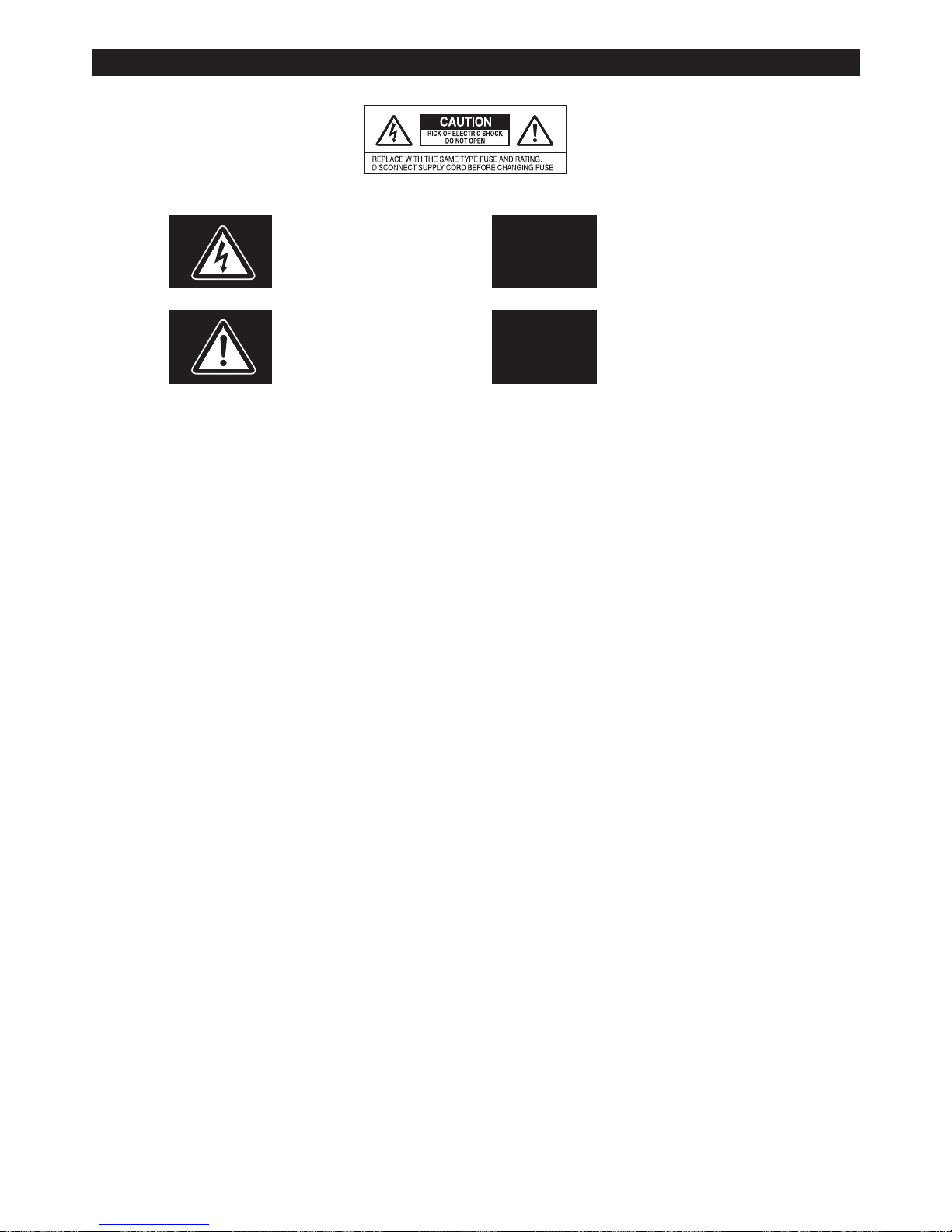
This symbos is intended to alert the user to
the presence of uninsulated “dangerous voltage” within the product’s enclosure that may
be of sufficient magnitude to conslitute a risk
of electric shock to persons.
CAUTION:
To reduce the risk of electric
shock, do not remove the top cover
(or the rear section). No user serviceable parts inside, refer servicing
to qualified service personnel.
This triangle on your component alert you to
important operation and maintenance instrucitons in this accompanying liferature.
WARNING:
To prevent fire or shock hazard do
not expose this appliance to rain
and moisture.
▒ IMPORTANT SAFTY INSTRUCTION ▒
XP-Series 3

XP-Series
4
HI-Z
LO-Z
H
I
1
2
K
H
z
d
B
+
-
d
B
15 15
M
o
n
i
t
o
r
C
o
n
t
r
o
l
0
10
5
010
E
f
f
e
c
t
C
o
n
t
r
o
l
010
M
I
D
2
.
5
K
H
z
d
B
+
-
d
B
15 15
L
O
W
8
0
H
z
d
B
+
-
d
B
15 15
GAIN
VOL
LINE
MIC
EFF
V
o
l
u
m
e
C
o
n
t
r
o
l
010
MON
MID
HIGH
1
LOW
(Control Section)
1
2
3
4
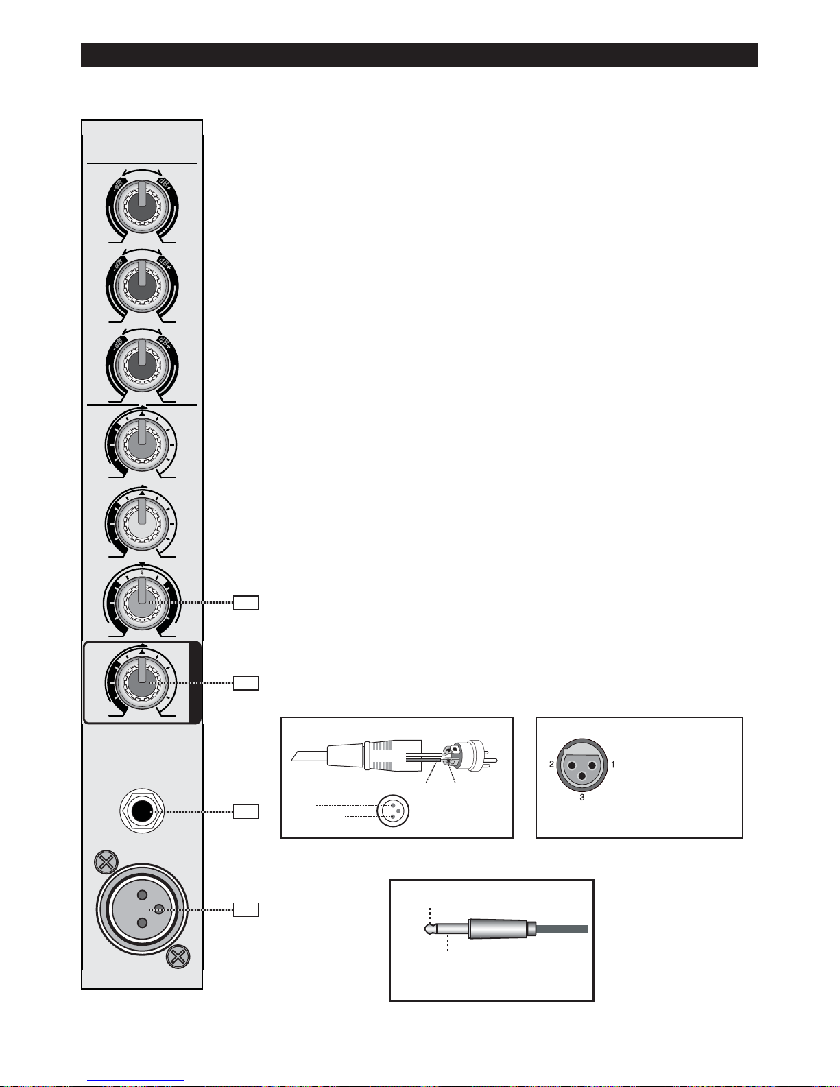
1. EQUALIZER CONTROLS ( HIGH, MID, LOW )
This is a 3-band equalizer that adjust the high frequency range, mid frequency
range, and low frequency range of each channel. Response is flat when the knobs
are in the center position. Rotating knob toward the right will boost the corresponding frequency band, and rotating knob toward the left will cut it. The followings are the base; range of boost or cut, and equalizer type of each band.
※Channel Frequency Character
※Master Frequency Response
2. MONITOR CONTROLS (MON)
This knob sends each channel’s signal out to an external amplifier, which powers your monitor speakers, via the MONITOR LINE OUT jack. Each channel’s
monitor send signal is controlled by the channel ’ s MON knob.
The monitor signal is for pre-VOLUME, so that adjust only the main mix. Each
MON control from off through triangle (the center detent position) on up to +15dB
of extra gain.
3. EFFECT CONTROLS ( EFF )
Each channel’s effects signal is controlled by the channel’s EFF knob, and the
overall effects level is controlled by the EFF LEVEL knob. The effects signal is for
post-EQ and post-VOLUME, so these control s affect the signal going to the effects processor, be it internal or external. Each EFF controls from off through triangle (the center detent position) on up to +10dB of extra gain. Normally the effects
signal is routed to the internal 32-bit precision digital stereo effects processor.
CONTROL MAX. BOOST/CUT FREQUENCY TYPE
HIGH
±15dB 12kHz Shelving
MID ±15dB 2.5kHz Shelving
LOW ±15dB 80Hz Shelving
▒ MONO (MIC CH.) - 1/3
(그림: Frequency Response)
Fig
XP-Series 4
XP-Series
5
(Control Section)
HI-Z
LO-Z
H
I
1
2
K
H
z
d
B
+
-
d
B
15 15
M
o
n
i
t
o
r
C
o
n
t
r
o
l
0
10
5
010
E
f
f
e
c
t
C
o
n
t
r
o
l
010
M
I
D
2
.
5
K
H
z
d
B
+
-
d
B
15 15
L
O
W
8
0
H
z
d
B
+
-
d
B
15 15
GAIN
VOL
LINE
MIC
EFF
V
o
l
u
m
e
C
o
n
t
r
o
l
010
MON
MID
HIGH
1
LOW
5
4
6
7
4. GAIN CONTROLS ( TRIM )
GAIN adjusts the input sensitivity of the MIC and LINE inputs. Gain may adjust signals from the outside to be adjusted to optional internal operating levels.
Through the XLR jack (MIC), there will be -20dB of gain at the knob fully down,
ramping to -50dB of gain fully up.
* Every time you plug something into a MIC or LINE input jack, you should perform the Level-Setting Procedure, to see “ how to use the TRIM knob.” *
5. VOLUME CONTROLS ( VOL )
The rotary VOLUME knob controls the channel’s level from off to, on up to
+20dB of additional gain when turned all the way up. The VOLUME control is
equivalent to a channel fader.
6. LINE INPUT (LINE)
Line input connects standard 1/4” plug unbalanced line; other than microphone
signals, it receives all other kinds of signals, from sources like keyboard, electronic
drum, tape recorder and etc.
7. MIC INPUT (MIC)
Electronically balanced XLR-type inputs for the connection of low impedance
microphones like the ones featured in major studio and live mixing consoles.
This type of input stage provides extraordinary low noise signal conversion at an
extremely low distortion rate (typical < 0.02%) even in the high frequency range.
Generally, any type of microphone can be connected as long as its pin assignment is in accordance to the diagram shown below.
※See illustration on how to connect
Fig 2 Line Input
Fig 1 Mic Input
Hot
Cold
Shield
1
2
3
Cold
Hot
Shield
Balanced XLR
Connectors
▒ MONO (MIC CH.) - 2/3
Pin1: GND
Pin2: HOT(+)
Pin3: COLD(-)
PHASE (Normal)
Pin1: GND
Pin2: COLD(-)
Pin3: HOT(+)
PHASE (Reverse)
MIC Input Jack(XLR) Pin 연결방법
How to connect mic input jack(XLR)
(Tip: Signal)
(Ring: Gnd)
(1/4”Phone Plug 연결 방법)
How to connect 1/4”phone plug
XP-Series 5
XP-Series
6
PLAY
R
TAPE
(CD)
MP3
SELECT
REC
L
VOL
V
o
l
u
m
e
C
o
n
t
r
o
l
010
TAPE/CD
OFF
ON
MUTE
HI-Z
LO-Z
VOL
LINE
MIC
V
o
l
u
m
e
C
o
n
t
r
o
l
010
(Input Section)
(Input Section)
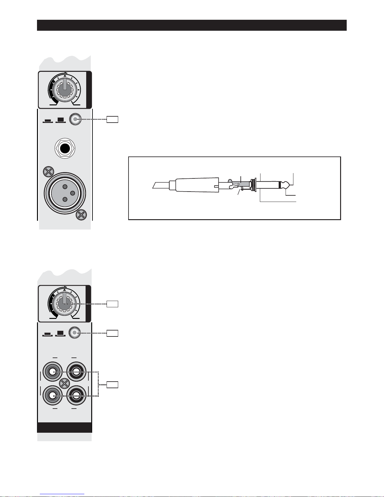
8. MUTE
The MUTE button mutes the input signal post fader, including all MIC/EFF/MON
sends. Signal/Peak stay functional.
HINT: Use the MUTE button for muting temporarily not used input channels without
changing the settings of the MIC/EFF/MON controls and the channel fader.
※As all other features are the same as the mono channels, please see the
description of the mono channels.
※ Unbalanced 1/4” TS Plug Connection
9. MP3 / TAPE(CD) VOLUME
This is a switch that adjust the playback volume.
(※Caution: Please reduce this volume to a minimum to prevent noise and trouble
when recording in MP3.)
10. MP3 / TAPE(CD) SELECT SWITCH
This is a switch that select a device to use. Each time the switch is pressed,
Tape(CD) and MP3 are selected alternately.
11. TAPE / CD IN and TAPE / CD OUT
These are unbalanced RCA-type connectors that match those typically used on
tape decks and CD players. Use RCA-to-RCA patch cables to make these connections.
Caution : When using the TAPE OUT connectors for recording, don’t connect
the output of the tape deck to the TAPE IN connectors. If you do, MAKE SURE the
TAPE IN LEVEL control is turned all the way down or you will create a feedback
loop that will cause great distress to you and everyone around you.
Signal
Ground
UnBalanced 1/4" TS Plug
Tip
Tip
Sleeve
Sleeve
8
10
9
11
▒ MONO (MIC CH.) - 3/3 ▒ TAPE/CD CH.
XP-Series 6

XP-Series
7
D
a
m
p
i
n
g
C
o
n
t
r
o
l
0
10
D
e
c
a
y
T
i
m
e
010
TIME
DAMP
LEV
R
e
v
e
r
b
L
e
v
e
l
010
R
E
V
E
R
B
D
E
L
A
Y
D
e
l
a
y
T
i
m
e
010
TIME
R
e
p
e
a
t
C
o
n
t
r
o
l
010
RPT
LEV
D
e
l
a
y
L
e
v
e
l
010
MON
M
o
n
i
t
o
r
L
e
v
e
l
010
EFFECTS
OFF
ON
EFFECT
STEREO
MONO
MODE
LONG
SHORT
DELAY TIME
(Effects Control Section)
(XP-1750C/2050C) (XP-1450)
1. REVERB DAMPING CONTROL
REVERB DAMPING CONTROL adjust the depth of the sound
effect.
2. REVERB TIME CONTROL
REVERB TIME CONTROL adjust the time of the sound effect.
3. REVERB LEVEL CONTROL
REVERB LEVEL CONTROL adjust the volume of the sound
effect. Raising too much volume for this effect, howling occurs
due to the Feedback.
4. DELAY TIME CONTROL
DELAY(ECHO) TIME CONTROL adjust the length of the sound
effect. This is used to use very long or short.
5. DELAY TIME CONTROL
DELAY(ECHO) TIME CONTROL adjust the length of the sound
effect minutely.
6. DELAY REPEAT CONTROL
DELAY(ECHO) REAPEAT CONTROL adjust the number of
iteration.
7. DELAY LEVEL CONTROL
DELAY(ECHO) LEVEL CONTROL adjust the volume of the
sound effect. Raising too much volume for this effect, howling
occurs due to the Feed back.
8. MONITOR LEVEL CONTROL
Reverb & Delay(Echo) is sent to monitor channel by this control. And you can adjust the volume of Reverb & Delay(Echo)
by using this control.
9. EFFECTS ON/OFF SWITCH
Using this switch, you can stop or activate the sound
effects(DELAY/REVERB).
10. MODE (ST/MONO) SELECTOR
This is a switch button you can choose mono or stereo.
11. EXT EFFECTS ON/OFF SWITCH JACK
Through this jack you can connect external switch that you
can play or stop the sound effect of this channel. Howling may
be occurred by using the Foot S/W.
FOOT S/W
D
a
m
p
i
n
g
C
o
n
t
r
o
l
0
10
D
e
c
a
y
T
i
m
e
010
TIME
D
e
l
a
y
T
i
m
e
010
TIME
R
e
p
e
a
t
C
o
n
t
r
o
l
010
RPT
M
o
n
i
t
o
r
L
e
v
e
l
010
MON
DAMP
EFFECTS
LEV
R
e
v
e
r
b
L
e
v
e
l
010
LONGSHORT
DELAY TIME
LEV
D
e
l
a
y
L
e
v
e
l
010
R
E
V
E
R
B
D
E
L
A
Y
STEREO
MONO
MODE
EFFECTS
▒ EFFECTS CH.
1
2
3
4
5
6
7
8
9
11
10
XP-Series 7
XP-Series
8
VOL
V
o
l
u
m
e
C
o
n
t
r
o
l
010
H
I
1
2
K
H
z
d
B
+
-
d
B
15 15
HIGH
M
I
D
2
.
5
K
H
z
d
B
+
-
d
B
15 15
MID
L
O
W
8
0
H
z
d
B
+
-
d
B
15 15
LOW
MASTER-1
XP-SERIES ~
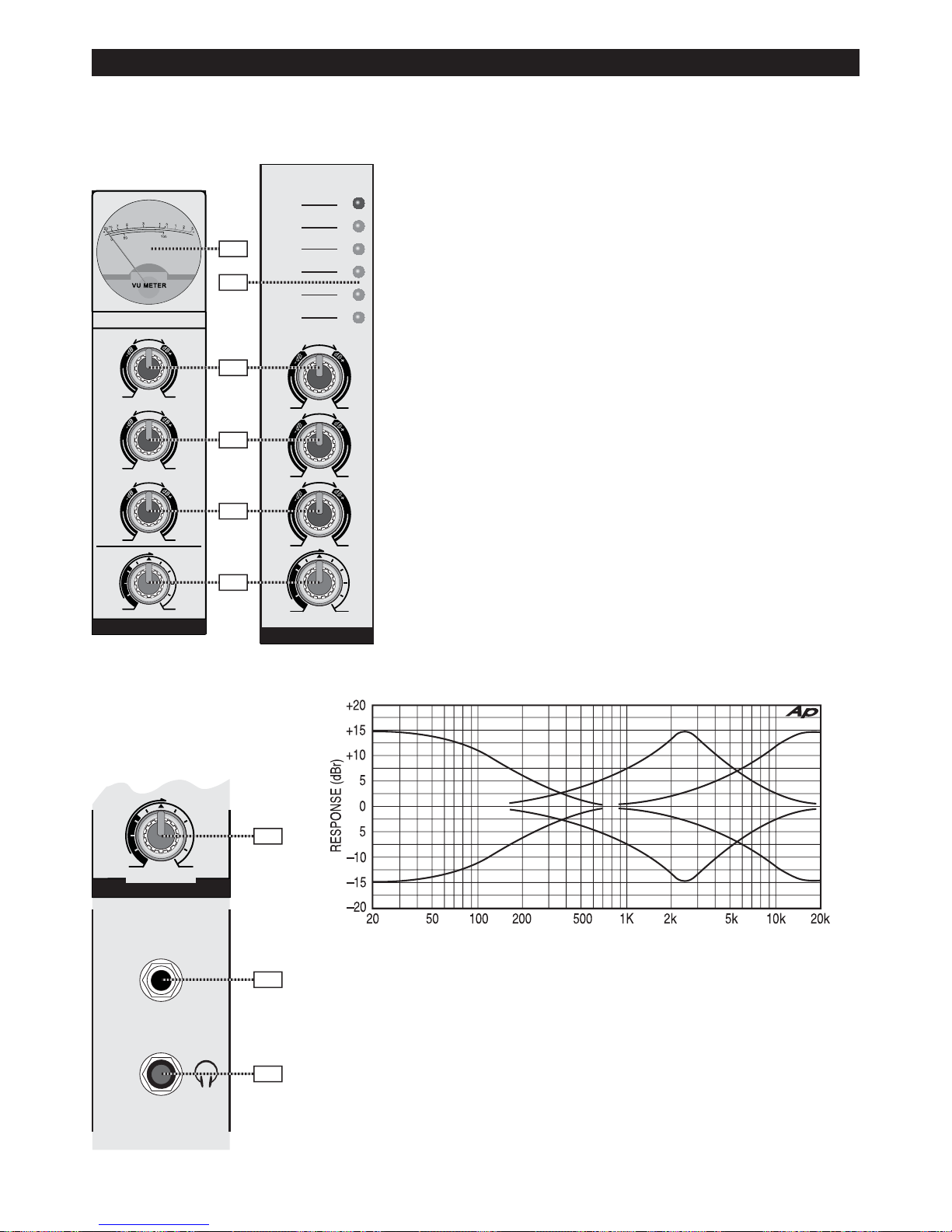
※Master Tone Frequency Response
7. HEADPHONE VOLUME
This control adjust the volume of the headphones connected.
8. MONITOR OUTPUT
Jack for the connection of the external monitor amplifier that monitor the output
signal.
9. HEADPHONE JACK
Jack for the connection of the headphone that monitor the output signal.
MASTER-1
XP-SERIES 2+1 OUTS POWERED MIXER
M
I
D
2
.
5
K
H
z
15 15
MID
H
I
1
2
K
H
z
d
B
+
-
d
B
d
B
+
-
d
B
15 15
HIGH
+3
L
O
W
8
0
H
z
d
B
+
-
d
B
15 15
LOW
VOL
V
o
l
u
m
e
C
o
n
t
r
o
l
010
0dB
-4
-9
-15
-21
MONITOR
OUT
VOL
PRE
V
o
l
u
m
e
C
o
n
t
r
o
l
010
~ERED MIXER
HEADPHONE
HEADPHONE
(XP-1750C/2050C) (XP-1450)
7
8
9
1
3
4
5
6
2
(Master Section)
(Master Monitor
Section)
1. OUTPUT VU-METER
Indicator for the displaying of operating status and the output volume.
You can monitor the operating status and the output volume using this
VU-METER.
2. MASTER LEVEL INDICATOR
This LED-chain indicates the level of output signal.
3. MASTER HIGH CONTROL
Level control to adjust the high frequency range of the XP1750C/2050C finally.
4. MASTER MIDDLE CONTROL
Level control to adjust the mid frequency range of the XP-1750C/2050C
finally.
5. MASTER LOW CONTROL
Level control to adjust the low frequency range of the XP-1750C/2050C
finally.
6. MASTER LEVEL CONTROL
Level control to adjust the volume of the XP-1750C/2050C finally.
The volume and operating status is displayed by MASTER-1’s VUMETER.
▒ MASTER CH.
(그림: Frequency Response)
Fig
XP-Series 8
XP-Series
9
USB
Remote
Receive
SD
MP3 PLAY / RECORD
PLAY DELSTOP NEXT BACKREC
USB/SD
No Disk
Please Add Disk
987654321 10
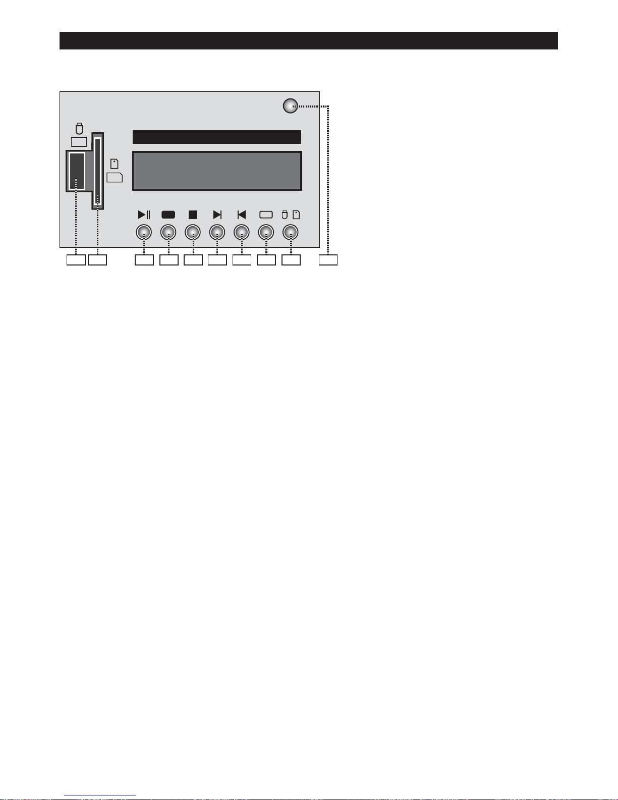
▒ MP3 PLAY & RECORDING (USB/SD)
(MP3 Section)
1. USB INSTERT SLOT
Slot for the connection of the USB memory
card.
2. SD CARD INSERT SLOT
Slot for the connection of the SD card.
3. REMOTE CONTROL RECEIVER
Part of the IR signal is received when you operating the remote control. (If there is obstacle
between the remote control and the receiver,
the remote control may not work.)
* On the remote control, see the following description. When you turn on the MP3 Player first, its volume is set 12
of 15 and you can adjust the volume.
4. FUNCTION INDICATOR
Watching this indicator, you can check the information of the working MP3 Player.
(※Caution: Please reduce the MP3/TAPE volume to a minimum to prevent noise and trouble when recording.)
5. PLAY & PAUSE BUTTON
Using this button, you can play or stop the MP3 File.
6. RECORD BUTTON
Recording is started when this button is pressed in the stop mode and the recording information is indicated
through the FUNCTION INDICATOR(4). At this time, the recording file is created since “00:01” which is indicated
in the FUNCTION INDICATOR(4) and the file name is FILE’XXX’. (FILE > RECORD > LINEIN > FILE’XXX’).
If you want to stop the recording you should press the stop button.
7. STOP BUTTON
If you press this button, the current function is stopped and the MP3 Player becomes initial state.
8. NEXT BUTTON
When you press this button, the next file is selected.
9. BACK BUTTON
When you press this button, the previous file is selected.
10. DELETE BUTTON
When the file is playing, if you press this button the file is selected and press this button one more, you can delete the file being played.
11. MEMORY SELECTION BUTTON
Pressing this button, you can choose to use any device of USB and SD card.
XP-Series 9

XP-Series
10
RISK OF ELECTRIC SHOCK
DO NOT OPEN
CAUTION !!
CAUTION : REPLACE WITH SAME TYPE FUSE AND
RATING. DISCONNECT SUPPLY CORD BEFORE CHANGEING
FUSE.
WARNING : TO REDUCE THE RISK OF FIRE OR
ELECTIRC SHOCK. DO NOT EXPOSE THIS EQUIPMENT TO
RAIN OR MOISTURE. DO TNO REMOVE COVER. NO USER
SERVICEABLE PARTS INSIDE. REFER SERVICING TO
QUALIFIED PERSONNEL.
CAUTION - HOT SURFACE AVOID CONTACT
MADE IN KOREA
SERIAL
NUMBER
XP-1450
Powered Mixer
XP-Series
2+v1 Outs
®
POWER
ON
OFF
CAUTION :
EXTERNAL SPEAKER
LOAD IMP. MINUM 4
CHANNEL - 2
Parallel
( 300W / 4 Ohm)
(Above 4Ω)
Speaker Connection
CHANNEL - 1
Parallel
( 300W / 4 Ohm)
(Above 4Ω)
PRIMARY FUSE
T4.0A / 250V
230V 50Hz, 660W
POWER INPUT
CAUTION:
TO REDUCE
THE RISK OF
FIRE REPLACE
WITH SAME
TYPE.
Pin 2
Pin 1
1+
2-(NC)
1-
2+(NC)
PRIMARY FUSE
T8.0A / 250V
230V 50Hz, 1200W
POWER INPUT
CAUTION :
EXTERNAL SPEAKER
LOAD IMP. MINUM 4
POWER
ON
OFF
CHANNEL - 1
Parallel
( 350W / 4 Ohm)
(Above 4Ω)
CHANNEL - 2
Parallel
( 350W / 4 Ohm)
(Above 4Ω)
CHANNEL - 3
Parallel
( 350W / 4 Ohm)
(Above 4Ω)
Speaker Connection
XP-1750C
Powered Mixer
XP-Series
3+1 Outs
MADE IN KOREA
SERIAL
NUMBER
RISK OF ELECTRIC SHOCK
DO NOT OPEN
CAUTION !!
CAUTION : REPLACE WITH SAMETYPE FUSE AND
RATING. DISCONNECT SUPPLY CORD BEFORE CHANGEING
FUSE.
WARNING : TO REDUCE THE RISK OF FIRE OR
ELECTIRC SHOCK. DO NOT EXPOSE THIS EQUIPMENT TO
RAIN OR MOISTURE. DO TNO REMOVE COVER. NO USER
SERVICEABLE PARTS INSIDE. REFER SERVICING TO
QUALIFIED PERSONNEL.
CAUTION - HOT SURFACE AVOID CONTACT
®
CAUTION:
TO REDUCE
THE RISK OF
FIRE REPLACE
WITH SAME
TYPE.
Pin 2
Pin 1
1+
2-(NC)
1-
2+(NC)
5
5
4
4
1
1
2
2
3
3
▒ REAR PARTS-1/2
(Rear Section) XP-1750C/2050C
(Rear Section) XP-1450
1. POWER SWITCH
Mains switch to turn the XP on or off. Please make sure to set the master faders to their minimum position before
switching the power on. This will save you, your audience, and the equipment from unnecessary stress. In case
additional external equipment is connected to the XP - e.g. power amps, FX units, EQs, etc. - please, proceed in
the following order when switching your equipment on:
1. switch on the FX units,
2. switch on the XP
3. switch on external power amps
When switching the power off, please proceed in the opposite order.
XP-Series 10

XP-Series
11
▒ REAR PARTS-2/2
▒ HOW TO CONNECT THE CABLE
5. SPEAKER OUTPUTS RIGHT / LEFT
The XP is equipped with professional Speakon high-performance connectors, offering electrical and mechanical
secure connection, which compiles to all security regulations. It also allows the use of high quality speaker cables
with diameters of 4 x 2,5mm². The pin assignment is shown at the rear panel of the XP.
CAUTION: The symbol representing the speaker connectors indicates the presence of touch-sensible voltages,
which can cause harm to body and health. Please, be sure to adhere to corresponding notes and instructions in
this owner’s manual when establishing speaker connections.
HINT: Using passive subwoofers, that add the input signal of the left and right channel, is not possible for technical reasons.
XP-Series Cable Application
MIC INPUT
balanced connection of
microphones
All phone jack
in/outputs
(except PHONES)
unbalanced external
equipment with
XLR-type in/output jacks
balanced external
equipment with
XLR-type in/output jacks
All phone jack
in/outputs
(except PHONES)
unbalanced external
equipment with
phone jack in/output jacks
balanced external
equipment with
phone jack in/output jacks
-
+
cold
hot
shield
1
3
2
Cable connection phone to XLR-type, unbalanced
2
3
1
+
hot cold
-
shield
Cable conne ct ion phone to XLR-type, balanc ed
-
+
hot
shield
+
hot
cold
-
shield
Standard phone-type, balanced
2
3
1
1
2
2 HOT (+)
1 SHIELD
3 COLD (-)
2 HOT (+)
1 SHIELD
3 COLD (-)
XP-Series 11

XP-Series
12
XP-1450/1750C/2050C
▒ Electrical Specification
● AMP RMS OUTPUTS
4Ω x 2Ch, 0.1% (T.H.D)
@ 1kHz
XP-1450 (300W+300W) / 4Ωx 2Ch.
XP-1750C (400W+400W+400W) / 4Ωx 3Ch.
XP-2050C (400W+400W+400W+400W) / 4Ωx 4 Ch.
● TOTAL HARMONIC DISTORTION MAIN AMP 0.1% 이하 @ 1kHz, MIC CH ~ MAIN AMP 0.1% 이하 @ 1kHz
● FREQUENCY RESPONSE
+1, -3dB 20Hz~20kHz @ 1W/4Ω (MAIN AMP)
+1, -3dB 20Hz~20kHz @ +4dB/10kΩ (MIXER PART)
● INPUT SENSITIVITY
MIC CH INPUT : -60 ~ -20dBv (XP-1750C/2050C)
: -450Bv (XP-1450)
LINE CH INPUT : -30 ~ 10dBv (XP-1750C/2050C)
: -20dBv (XP-1450)
TAPE INPUT : -20dBV
@ RS = 150 Ω(20Hz ~ 20kHz)
● TAPE REC OUTPUT 0dBV / @ RS = 150 Ω(20Hz ~ 20kHz)
● HEADPHONES OUTPUT POWER 5V / 75 Ω
● HUM & NOISE -75dB Below (“A”Weight filter)
● NOISE -80dB Below (“A”Weight filter)
● TONE CONTROL
●MIC CH TONE CONTROL
LOW 80Hz ±15dB
MID 2.5KHz ±15dB
HIGH 12KHz ±15dB
●MASTER CH TONE CONTROL
LOW 80Hz ±15dB
MID 2.5KHz ±15dB
HIGH 12KHz ±15dB
● LEVEL INDICATOR VU-Meter (XP-1750C/2050C) / LED 6-Dot Display (XP-1450)
● EFFECTS 32-Bit Digital Stereo Process
● POWER CONSUNPTION XP-2050C: 1600W / XP-1750C: 1200W / XP-1450: 660W
● POWER INPUT AC 220V, 50 / 60Hz
▒ General Specification
● PRODUCT TYPE Hard Case (XP-2050C/1750C) / Wooden Case (XP-1450)
● Size (W X H X D)mm
XP-2050C:
585 x 280 x 455 mm: (With Cover)
585 x 275 x 315 mm: (With Out Cover)
XP-1450:
425 x 265 x 320 mm:
XP-1750C:
540 x 280 x 455 mm: (With Cover)
540 x 275 x 315 mm: (With Out Cover)
● Weight (Net) Kg XP-2050C: 28Kg / XP-1750C: 21.5Kg / XP-1450: 15.5Kg
▒ ACCESSORY
● OPERATION MANUAL 1 Copy
● SPARE FUSE 1 Ea (Built in Fuse Holder)
● AC POWER CORD 1 Ea
▒ SPECIFICATION
XP-Series 12

▒ ﻢﻬﻣ ﻲﻨﻤﻳا تﺎﻜﻧ ﻞﻤﻌﻟارﻮﺘﺳد ▒
XP-Series 13
.
.
دﻮﺟو درﻮﻣ رد ﺮﺑرﺎﻛ ﻪﺑ راﺪﺸﻫ ﺖﻬﺟ ﻪﻧﺎﺸﻧ ﻦﻳا"كﺎﻧﺮﻄﺧ ژﺎﺘﻟو" نوﺪﺑ
ﻪﺑ ار ﻲﮕﺘﻓﺮﮔ قﺮﺑ ﺮﻄﺧ ﺪﻧاﻮﺗ ﻲﻣ ﻪﻛ ﺪﺷﺎﺑ ﻲﻣ لﻮﺼﺤﻣ ﻪﻈﻔﺤﻣ رد ﻖﻳﺎﻋ
ﻪﺘﺷاد هاﺮﻤﻫﺪﺷﺎﺑ.
دﺮﻛرﺎﻛ ﻞﻤﻌﻟارﻮﺘﺳد يروآدﺎﻳ ﺖﻬﺟ يراﺪﺸﻫ ،تﺎﻌﻄﻗ يور ﻪﻧﺎﺸﻧ ﻦﻳا
تﺎﻴﻠﻤﻋ ﺎﻳ ﺪﺷﺎﺑ ﻲﻣ ﻪﭼﺮﺘﻓد ﻦﻳا رد دﻮﺟﻮﻣ ﻢﻬﻣ يراﺪﻬﮕﻧ.
ﻲﻳﻻﺎﺑ رد ،ﻲﮕﺘﻓﺮﮔ قﺮﺑ ﺮﻄﺧ ﺶﻫﺎﻛ ﺖﻬﺟ)ﻲﺒﻘﻋ ﺶﺨﺑ ﺎﻳ ( ار
ﺪﻳراﺪﻧﺮﺑ . ﻞﺑﺎﻗ هﺎﮕﺘﺳد ﺮﺑرﺎﻛ ﻂﺳﻮﺗ هﺎﮕﺘﺳد ﻞﺧاد تﺎﻌﻄﻗ زا ﻚﻳ ﭻﻴﻫ
عﻮﺟر ﺲﻳوﺮﺳ زﺎﺠﻣ ﻞﻨﺳﺮﭘ ﻪﺑ هﺎﮕﺘﺳد ﺲﻳوﺮﺳ ياﺮﺑ ،ﺪﻨﺘﺴﻴﻧ ﺲﻳوﺮﺳ
ﺪﻴﻨﻛ.
ضﺮﻌﻣ رد ار هﺎﮕﺘﺳد ،ﻲﮕﺘﻓﺮﮔ قﺮﺑ و يزﻮﺳ ﺶﺗآ زا يﺮﻴﮔﻮﻠﺟ ﺖﻬﺟ
ﺪﻴﻫﺪﻧ راﺮﻗ ﺖﺑﻮﻃر و نارﺎﺑ.
هﺎﮕﺘﺳد زا هدﺎﻔﺘﺳا زا ﻞﺒﻗ ﺪﻳﺎﺑ ار يدﺮﻜﻠﻤﻋ و ﻲﻨﻤﻳا تﺎﻜﻧ ﻪﻴﻠﻛدﺮﻛ ﻪﻌﻟﺎﻄﻣ.
ﻪﭼﺮﺘﻓد يراﺪﻬﮕﻧ
ﺑ ﺪﻳﺎﺑ ار يدﺮﻜﻠﻤﻋ و ﻲﻨﻤﻳا يﺎﻤﻨﻫار ﻪﭼﺮﺘﻓدﺪﻳراد ﻪﮕﻧ دﻮﺧ دﺰﻧ يﺪﻌﺑ تﺎﻌﺟاﺮﻣ ياﺮ.
ﺎﻫراﺪﺸﻫ ﻪﺑ ﻪﺟﻮﺗ
دﺮﻛ ﺖﻳﺎﻋر ﺪﻳﺎﺑ ار ﺎﻤﻨﻫار ﻪﭼﺮﺘﻓد و هﺎﮕﺘﺳد ﻦﻳا يﺎﻫراﺪﺸﻫ ﻪﻴﻠﻛ.
ﺪﻴﻨﻛ يوﺮﻴﭘ ﻞﻤﻌﻟارﻮﺘﺳد زا. دﺮﻛ ﺖﻳﺎﻋر ﺪﻳﺎﺑ ار يﺮﺑرﺎﻛ و ﻲﺗﺎﻴﻠﻤﻋ تﺎﻜﻧ ﻪﻴﻠﻛ.
ﺖﺑﻮﻃر و بآ

ﺖﺑﻮﻃر و بآ تروﺎﺠﻣ رد ﺪﻳﺎﺒﻧ ار هﺎﮕﺘﺳد ﻦﻳا)ﻤﺣ ناو ﻚﻳدﺰﻧ ًﻼﺜﻣ ﻂﻴﺤﻣ رد ،ﻲﻳﻮﺸﺘﺧر ﻦﮕﻟ ،ﻲﻳﻮﺸﻓﺮﻇ ﻚﻨﻴﺳ ،ﻲﻳﻮﺷور ﻚﻨﻴﺳ ،مﺎ
XP-Series 14
هﺮﻴﻏ و ﺎﻨﺷ ﺮﺨﺘﺳا تروﺎﺠﻣ رد ،بﻮﻃﺮﻣ (دﺮﻛ هدﺎﻔﺘﺳا.
ﺪﺷﺎﺑ ﻲﻣ هﺪﺷ هﺪﻴﺷﺎﭘ بآ ﻞﺑﺎﻘﻣ رد ﻆﻓﺎﺤﻣ ﺪﻗﺎﻓ هﺎﮕﺘﺳد ﻦﻳا ﻪﻜﻨﻳا ﻞﻴﻟﺪﺑ: ﻪﻛ دﻮﺷ ﺪﻴﻗ ﻪﭼﺮﺘﻓد رد ﺪﻳﺎﺑ ﺎﻳ نﺪﻴﺷﺎﭘ ضﺮﻌﻣ رد هﺎﮕﺘﺳد ﻦﻳا زا
ﭻﻴﻫ و ﺪﻴﻨﻜﻧ هدﺎﻔﺘﺳا بآ ندﺮﻛ ﻪﻜﭼ بآ ياراد ﻲﺷ)ناﺪﻠﮔ ﺪﻨﻧﺎﻣ (ﺪﻴﻫﺪﻧ راﺮﻗ نآ يور ار.
ﺎﻣﺮﮔ
ﺪﻨﻨﻛ ﻲﻣ ﺪﻴﻟﻮﺗ ﺎﻣﺮﮔ ﻪﻛ ﻲﻣزاﻮﻟ ﺮﻳﺎﺳ ﺎﻳ ،زﺎﮔ قﺎﺟا ،ﺖﻨﻤﻟا ،رﻮﺗﺎﻳدار ﺪﻨﻧﺎﻣ ازﺎﻣﺮﮔ ﻊﺑﺎﻨﻣ زا رود ﺪﻳﺎﺑ ار هﺎﮕﺘﺳد ﻦﻳا)ﺮﻳﺎﻓ ﻲﻠﭙﻣآ ﻞﻣﺎﺷ ( راﺮﻗ
داد.
قﺮﺑ
ﺮﻛذ ﺎﻤﻨﻫار ﻪﭼﺮﺘﻓد رد ﻪﻛ يا ﻪﻧﻮﮕﻧﺎﻤﻫ ﻪﺑ ﺖﺳرد ﺪﻳﺎﺑ ار هﺎﮕﺘﺳد ﻦﻳا دﺮﻛ ﻞﺻو قﺮﺑ ﻪﺑ هﺪﺷ هداد نﺎﺸﻧ هﺎﮕﺘﺳد يور ﺎﻳ هﺪﺷ.
قﺮﺑ ﻞﺑﺎﻛ زا ﺖﻈﻓﺎﺤﻣ
دﻮﺟو دﺮﻴﮔ ﻲﻣ راﺮﻗ نآ يور ﻪﻛ ﻲﻳﺎﻴﺷا ﻂﺳﻮﺗ ﻞﺑﺎﻛ نﺪﺷ ﻢﺧز و ندﺮﻛ ﺪﮕﻟ لﺎﻤﺘﺣا ﻪﻛ دﺮﻛ ﻲﺣاﺮﻃ يا ﻪﻧﻮﮕﺑ ﺪﻳﺎﺑ ار قﺮﺑ ﻞﺑﺎﻛ ﺮﻴﺴﻣ
و ﻪﻄﺳاو ﻢﻴﺳ ،ﺎﻫ ﻪﺧﺎﺷود و قﺮﺑ ﻞﺑﺎﻛ ﻪﺑ و ﺪﺷﺎﺑ ﻪﺘﺷاﺪﻧﻞﺤﻣ ﺎﮕﺘﺳد زا ﻞﺑﺎﻛ جوﺮﺧﺖﺷاد ﻲﺻﺎﺧ ﻪﺟﻮﺗ ه.
ﺪﺷﺎﺑ ﻲﻣ هدﺎﻔﺘﺳا ﻼﺑ هﺎﮕﺘﺳد ﻪﻛ ﻲﻳﺎﻫ نﺎﻣز
ﺪﻴﺸﻛ ﺰﻳﺮﭘ زا ﺪﺷﺎﺑ ﻲﻣ هدﺎﻔﺘﺳا ﻼﺑ ﻲﻧﻻﻮﻃ تﺪﻣ ياﺮﺑ هﺎﮕﺘﺳد ﻪﻛ ﻲﻌﻗاﻮﻣ رد ﺪﻳﺎﺑ ار هﺎﮕﺘﺳد قﺮﺑ ﻞﺑﺎﻛ.
هﺎﮕﺘﺳد يرﺎﻛﺰﻴﻤﺗ
دﺮﻛ ﺰﻴﻤﺗ ﺖﺳا هدﺮﻛ ﺺﺨﺸﻣ هﺪﻧزﺎﺳ ﻪﻛ ﻪﻧﻮﮕﻧﺎﻤﻫ ﺪﻳﺎﺑ ار هﺎﮕﺘﺳد.
هﺎﮕﺘﺳد ﻪﺑ تﺎﻌﻳﺎﻣ و لﺎﻐﺷآ دورو
دﻮﺸﻧ دراو هﺎﮕﺘﺳد ﻪﻈﻔﺤﻣ ﻪﺑ تﺎﻌﻳﺎﻣ و لﺎﻐﺷآ ﺪﻴﺷﺎﺑ ﺐﻇاﻮﻣ ﺪﻳﺎﺑ.
نﻮﻴﺳاﺰﻳرﻼﭘ ﺎﻳ ترا لﺎﺼﺗا
ﺪﺷﺎﺑ ترا لﺎﺼﺗا ياراد ﺪﻳﺎﺑ هﺎﮕﺘﺳد ﻦﻳا. ﺪﻧﻮﺸﻧ باﺮﺧ هﺎﮕﺘﺳد نﻮﻴﺳاﺰﻳرﻼﭘ و ترا لﺎﺼﺗا راﺰﺑا ﺎﺗ داد مﺎﺠﻧا ار مزﻻ تﺎﻣاﺪﻗا ﺪﻳﺎﺑ.
ﺪﻨﺷﺎﺑ ﻲﻣ ﺲﻳوﺮﺳ ﺪﻨﻣزﺎﻴﻧ ﻪﻛ ﻲﺗارﺎﺴﺧ

د ﺪﻳﺎﺑ هﺎﮕﺘﺳد ﻦﻳادﻮﺷ ﺲﻳوﺮﺳ زﺎﺠﻣ ﻞﻨﺳﺮﭘ ﻂﺳﻮﺗ ﺮﻛﺬﻟا ﻞﻳذ ﻊﻗاﻮﻣ ر:
XP-Series 15
- ﺪﺷﺎﺑ هﺪﻳد ﺐﻴﺳآ ﻪﺧﺎﺷود ﺎﺑ قﺮﺑ ﻞﺑﺎﻛ.
- دﻮﺷ دراو هﺎﮕﺘﺳد ﻪﺑ تﺎﻌﻳﺎﻣ ﺎﻳ لﺎﻐﺷآ.
- ﺪﺷﺎﺑ ﻪﺘﻓﺮﮔ راﺮﻗ نارﺎﺑ ﺮﻳز هﺎﮕﺘﺳد.
- ﺎﻳ ﺪﺷﺎﺒﻧ لﺎﻣﺮﻧ يدﺮﻜﻠﻤﻋ ﻂﻳاﺮﺷ رد هﺎﮕﺘﺳدﺪﺷﺎﺑ ﻪﺘﺷاد دﺮﻜﻠﻤﻋ رد ﻲﺳﻮﺴﺤﻣ تاﺮﻴﻴﻐﺗ.
- ﻳ ﺪﺷﺎﺑ هدﺎﺘﻓا هﺎﮕﺘﺳدﺪﺷﺎﺑ هﺪﻳد ﺐﻴﺳآ هﺎﮕﺘﺳد ﻪﻈﻔﺤﻣ ﺎ.
هﺎﮕﺘﺳد ﺲﻳوﺮﺳ
ﺪﻨﻛ ماﺪﻗا ﺖﺳا هﺪﺷ ﺮﻛذ ﺎﻤﻨﻫار ﻪﭼﺮﺘﻓد رد ﻪﭽﻧآ زا ﺶﻴﺑ هﺎﮕﺘﺳد ﺲﻳوﺮﺳ ﻪﺑ ﺖﺒﺴﻧ ًﺎﺼﺨﺷ ﺪﻳﺎﺒﻧ هﺎﮕﺘﺳد ﺮﺑرﺎﻛ . ﺪﻳﺎﺑ ﺲﻳوﺮﺳ دراﻮﻣ ﺮﻳﺎﺳ
دﻮﺷ مﺎﺠﻧا ﺖﻛﺮﺷ زﺎﺠﻣ ﻞﻨﺳﺮﭘ ﻂﺳﻮﺗ.

▒ ﻮﻧﻮﻣ)نﻮﻓوﺮﻜﻴﻣ (1/3
ﻛ
XP-Series 16
)هﺎﮕﺘﺳد لﺮﺘﻨﻛ(
1. يﺎﻫ لﺮﺘﻨﻛ رﺰﻳﻻﻮﻛا)ﻦﻴﻳﺎﭘ ،ﻂﺳﻮﺘﻣ ،ﻻﺎﺑ(
رﺰﻳﻻﻮﻛا ﻚﻳ ﻦﻳا3 ﺪﻨﻛ ﻲﻣ ﻢﻴﻈﻨﺗ ﻦﻴﻳﺎﭘ و ﻂﺳﻮﺘﻣ ،ﻻﺎﺑ ﺲﻧﺎﻛﺮﻓ رد ار لﺎﻧﺎﻛ ﺮﻫ ﻪﻛ ﺪﺷﺎﺑ ﻲﻣ ﺪﻧﺎﺑ .
سﺎﻜﻌﻧا ،ﺪﻨﺘﺴﻫ ﻂﺳو رد ﺎﻫ مﻮﻟو ﻪﻜﻴﻣﺎﮕﻨﻫﺖﺳا ﺖﺧاﻮﻨﻜﻳ . ﺚﻋﺎﺑ ﺖﺳار ﺖﻤﺳ ﻪﺑ مﻮﻟو نﺪﻧﺎﺧﺮﭼ ﺎﺑ
ﺑ ﭗﭼ ﺖﻤﺳ ﻪﺑ مﻮﻟو نﺪﻧﺎﺧﺮﭼ و ﻪﻃﻮﺑﺮﻣ ﺲﻧﺎﻛﺮﻓ ﺪﻧﺎﺑ ﺶﻳاﺰﻓا ﺪﻫاﻮﺧ ﺲﻧﺎﻛﺮﻓ ﻊﻄﻗ و ﺶﻫﺎﻛ ﺚﻋﺎ
ﺪﺷ .ﺪﻫد ﻲﻣ نﺎﺸﻧ ار ﺪﻧﺎﺑ ﺮﻫ رﺰﻳﻻﻮﻛا عﻮﻧ و ﺶﻫﺎﻛ ﺎﻳ ﺶﻳاﺰﻓا يﺎﻨﺒﻣ ﺮﻳدﺎﻘﻣ ﺮﻳز لوﺪﺟ.
لﺎﻧﺎﻛ ﺲﻧﺎﻛﺮﻓ تﺎﺼﺨﺸﻣ
لﺮﺘﻨﻛ ﺶﻳاﺰﻓا ﺮﺜﻛاﺪﺣ /ﺶﻫﺎ
ﻻﺎﺑ
ﻂﺳﻮﺘﻣ
ﻦﻴﻳﺎﭘ
±15dB
±15dB
±15dB
ﺲﻧﺎﻛﺮﻓ عﻮﻧ
12kHz Shelving
2.5kHz Shelving
80Hz Shelving
ﺎﻜﻌﻧاﻲﻠﺻا ﺲﻧﺎﻛﺮﻓ س
)ﻞﻜﺷ :ﺲﻧﺎﻛﺮﻓ سﺎﻜﻌﻧا(
2. رﻮﺘﻴﻧﺎﻣ يﺎﻫ لﺮﺘﻨﻛ)MON(
ﻚﺟ ﻖﻳﺮﻃ زا ﻪﻛ ﺪﺘﺳﺮﻓ ﻲﻣ ﻲﺟرﺎﺧ ﺮﻳﺎﻓ ﻲﻠﭙﻣآ ﻚﻳ ﻪﺑ ار ﻲﻟﺎﻧﺎﻛ ﺮﻫ لﺎﻨﮕﻴﺳ ،مﻮﻟو ﻦﻳا
MONITOR LINE OUTﺪﻨﻠﺑ ،ﮔﺪﻨﻛ ﻲﻣ ﻦﺷور ار ﺎﻤﺷ رﻮﺘﻴﻧﺎﻣ يﺎﻫﻮ . لﺎﻨﮕﻴﺳ ﻪﻛ ﻲﻟﺎﻧﺎﻛ رﻮﺘﻴﻧﺎﻣ ﺮﻫ
مﻮﻟو ﻂﺳﻮﺗ ﺪﺘﺳﺮﻓ ﻲﻣMON لﺮﺘﻨﻛ لﺎﻧﺎﻛدﻮﺷ ﻲﻣ.

ﺪﺷﺎﺑ ﻲﻣ مﻮﻟو ﺶﻴﭘ ﻢﻴﻈﻨﺗ ياﺮﺑ رﻮﺘﻴﻧﺎﻣ لﺎﻨﮕﻴﺳﺪﻫد ﻲﻣ مﺎﺠﻧا ار ﻲﻠﺻا ﺲﻜﻴﻣ ﻂﻘﻓ ﻞﻴﻟد ﻦﻴﻤﻫ ﻪﺑ ، . يﺎﻫ لﺮﺘﻨﻛ زا ﻚﻳ ﺮﻫ
XP-Series 17
MON ﺚﻠﺜﻣ ﺎﺗ ﻲﺷﻮﻣﺎﺧ زا)يﺰﻛﺮﻣ هﺪﻧراﺪﻬﮕﻧ ﺖﻴﻌﻗﻮﻣ ( ﺎﺗ ﻻﺎﺑ رد15db دﻮﺷ ﻲﻣ ﻪﻓﺎﺿا.
3. مﻮﻟو ﻂﺳﻮﺗ لﺎﻨﮕﻴﺳ يﺎﻫ ﺖﻜﻓا زا ﻚﻳ ﺮﻫEFF ﺢﻄﺳ و دﻮﺷ ﻲﻣ لﺮﺘﻨﻛ لﺎﻧﺎﻛ ﻲﻠﻛﺎﻫ ﺖﻜﻓا مﻮﻟو ﺎﺑEFF LEVEL ﻲﻣ لﺮﺘﻨﻛ
دﻮﺷ . هاﻮﺧ ﺎﻫ ﺖﻜﻓا ﺮﮕﺷزادﺮﭘ ﻪﺑ هﺪﻧور لﺎﻨﮕﻴﺳ ﺮﺑ ﺎﻫ لﺮﺘﻨﻛ ﻦﻳا ﻦﻳاﺮﺑﺎﻨﺑ ﺪﺷﺎﺑ ﻲﻣ مﻮﻟو و رﺰﻳﻻﻮﻛا زا ﺮﺗاﺮﻓ ﺎﻫ ﺖﻜﻓا لﺎﻨﮕﻴﺳ
ﺪﻧراﺬﮔ ﻲﻣ ﺮﻴﺛﺎﺗ ﻲﺟرﺎﺧ ﺎﻳ ﻲﻠﺧاد . يﺎﻫ لﺮﺘﻨﻛ زا ﻚﻳ ﺮﻫEFF ﺚﻠﺜﻣ ﺎﺗ ﻲﺷﻮﻣﺎﺧ زا)يﺰﻛﺮﻣ هﺪﻧراﺪﻬﮕﻧ ﺖﻴﻌﻗﻮﻣ ( رد ﺎﺗ ﻻﺎﺑ
لﺎﺘﻴﺠﻳد ﻮﻳﺮﺘﺳا ﺖﻜﻓا ﺮﮕﺷزادﺮﭘ ﺖﻤﺳ ﻪﺑ ﺎﻫ ﺖﻜﻓا لﺎﻨﮕﺳ ًﻻﻮﻤﻌﻣ32 ﺪﻧور ﻲﻣ ﻲﻠﺧاد ﻲﺘﻴﺑ.
10db دﻮﺷ ﻲﻣ ﻪﻓﺎﺿا . ﻖﻴﻗد

▒ ﻮﻧﻮﻣ)نﻮﻓوﺮﻜﻴﻣ (2/3
XP-Series 18
)هﺎﮕﺘﺳد لﺮﺘﻨﻛ(
4. هﺪﻨﻨﻛ ﺖﻓﺎﻳرد يﺎﻫ لﺮﺘﻨﻛ )TRIM(
GAIN يدورو يﺎﻫ لﺎﻨﮕﻴﺳ يدورو ﺖﻴﺳﺎﺴﺣ هﺪﻨﻨﻛ ﻢﻴﻈﻨﺗMIC وLINE ﺪﺷﺎﺑ ﻲﻣ .GAIN يﺎﻫ لﺎﻨﮕﻴﺳ
ﺪﻨﻛ ﻲﻣ ﻢﻴﻈﻨﺗ ﺪﻧﻮﺷ ﻢﻴﻈﻨﺗ يرﺎﻴﺘﺧا ﻲﻠﺧاد يدﺮﻜﻠﻤﻋ حﻮﻄﺳ ﺖﻬﺟ ﺪﻳﺎﺑ ﻪﻛ ار ﻲﺟرﺎﺧ . ﻚﺟ ﻖﻳﺮﻃ زاXLR
)MIC( ،20- db ﺎﺗ و ﺪﺷ ﺪﻫاﻮﺧ ﻢﻛ ًﻼﻣﺎﻛ مﻮﻟو رد ﻲﺘﻓﺎﻳرد50- db ﺖﻓر ﺪﻫاﻮﺧ ﻻﺎﺑ.
* يدورو ﻚﺟ ﻖﻳﺮﻃ زا ﻲﻫﺎﮕﺘﺳد لﺎﺼﺗا رﺎﺑ ﺮﻫ ﺎﺑMIC ﺎﻳLINEﺪﻧور ﺪﻳﺎﺑ ، ﺪﻴﻫد مﺎﺠﻧا ار ﺢﻄﺳ تﺎﻤﻴﻈﻨﺗ
ﺪﻴﻤﻬﻔﺑ ﺎﺗ" مﻮﻟو زا ﻪﻧﻮﮕﭼTRIM ﺪﻴﻨﻛ هدﺎﻔﺘﺳا"*.
5. مﻮﻟو يﺎﻫ لﺮﺘﻨﻛ)VOL(
ﺎﺗ نﺪﺷ ﻦﺷور ﺎﺗ ﻲﺷﻮﻣﺎﺧ زا لﺎﻧﺎﻛ ﺢﻄﺳ هﺪﻨﻨﻛ لﺮﺘﻨﻛ ﻲﺸﺧﺮﭼ مﻮﻟو20 +db ﺪﺷﺎﺑ ﻲﻣ ﻲﻓﺎﺿا ﺖﻓﺎﻳرد .
ﻲﻣ لﺎﻧﺎﻛ هﺪﻨﻨﻛ ﻢﻛ ﻚﻳ لدﺎﻌﻣ مﻮﻟو لﺮﺘﻨﻛ.
ﺪﺷﺎﺑ
ﺪﻨﻛ ﻲﻣ ﺖﻓﺎﻳرد هﺮﻴﻏ و تﻮﺻ ﻂﺒﺿ ،ﻲﻜﻴﻧوﺮﺘﻜﻟا مارد ،درﻮﺒﻴﻛ ﺪﻨﻧﺎﻣ ﻲﻌﺑﺎﻨﻣ زا ار ﺎﻫ.
يدورو عﻮﻧ ﻦﻳا
ﻲﻨﻴﻳﺎﭘ رﺎﻴﺴﺑ جﺎﺟﻮﻋا خﺮﻧ ﺎﺑ ار ﻦﻴﻳﺎﭘ ﺰﻳﻮﻧ لﺎﻨﮕﻴﺳ يا هدﺎﻌﻟا قﻮﻓ رﻮﻄﺑ) ًﻻﻮﻤﻌﻣ< 0.02% (ﺪﻨﻛ ﻲﻣ ﻞﻳﺪﺒﺗ .
6. يدوروLINE )LINE(
يدوروLINE ﻣ ﻢﻴﺳ هﺪﻨﻨﻛ ﻞﺼﺘ1.4 لﺎﻨﮕﻴﺳ ﺮﻳﺎﺳ ،نﻮﻓوﺮﻜﻴﻣ يﺎﻫ لﺎﻨﮕﻴﺳ ﺰﺠﺑ و ﺪﺷﺎﺑ ﻲﻣ نزاﻮﺘﻣ ﺎﻧ ﻲﭽﻨﻳا
7. يدوروMIC )MIC(
يﺎﻫ يدوروXLR ﻜﻴﻣ ﺪﻨﻧﺎﻣ ﻢﻛ ﺲﻧاﺪﭙﻣا ياراد يﺎﻫ نﻮﻓوﺮﻜﻴﻣ لﺎﺼﺗا ﺖﻬﺟ ﻲﻜﻴﻧوﺮﺘﻜﻟا نزاﻮﺘﻣ يﺎﻫ نﻮﻓوﺮ
درا
د دﺮﺑرﺎﻛ هﺪﻧز ﺲﻜﻴﻣ يﺎﻫ لﻮﺴﻨﻛ و گرﺰﺑ يﺎﻫﻮﻳدﻮﺘﺳا . ﻻﺎﺑ يﺎﻫ ﺲﻧﺎﻛﺮﻓ رد ﻲﺘﺣ
ﺷﺎﺑ ﺮﻳز يﺎﻫ ﻞﻜﺷ ﻖﺑﺎﻄﻣ نآ ﻦﻴﭘ ﻪﻛ ار ﻲﻧﻮﻓوﺮﻜﻴﻣ عﻮﻧ ﺮﻫ ًﻻﻮﻤﻌﻣدﺮﻛ ﻞﺼﺘﻣ ناﻮﺗ ﻲﻣ ﺪ.
*ﺪﻴﻳﺎﻣﺮﻓ هﺪﻫﺎﺸﻣ ار لﺎﺼﺗا هﻮﺤﻧ:

▒ ﻮﻧﻮﻣ)نﻮﻓوﺮﻜﻴﻣ (3/3 ▒ راﻮﻧ ﺶﺨﺑ /CD
XP-Series 19
)يدورو ﺶﺨﺑ(
8. اﺪﺻ ﻲﺑ
ﺪﻴﻠﻛMUTE زا ﻲﻟﺎﺳرا يﺎﻫ لﺎﻨﮕﻴﺳ ﻪﻴﻠﻛ ﻞﻣﺎﺷ يدورو لﺎﻨﮕﻴﺳMIC / EFF / MON ﻲﻣ اﺪﺻ ﻲﺑ ار
ﺪﻨﻛ .دﻮﺑ ﺪﻨﻫاﻮﺧ ارﺎﻛ نﺎﻨﭽﻤﻫ نآ جوا و لﺎﻨﮕﻴﺳ.
ﻪﺘﻜﻧ :ﻛ زا ﺪﻴﻠMUTE ﺮﻴﻴﻐﺗ نوﺪﺑ يدورو يﺎﻫ لﺎﻧﺎﻛ ياﺮﺑ ﻪﻧ و ﺎﻫ لﺎﻨﮕﻴﺳ ﺖﻗﻮﻣ ندﺮﻛ اﺪﺻ ﻲﺑ ياﺮﺑ
يﺎﻫ لﺮﺘﻨﻛ تﺎﻤﻴﻈﻨﺗMIC / EFF / MON ﺪﻴﻨﻛ هدﺎﻔﺘﺳا لﺎﻧﺎﻛ هﺪﻨﻫﺎﻛ و.
* ﺖﻫﺎﺒﺷ ﻞﻴﻟﺪﺑ يﺎﻫ لﺎﻧﺎﻛ ﻪﺑ ﺪﻴﻠﻛ ﻦﻳا يﺎﻫ ﻲﮔﮋﻳو ﺮﻳﺎﺳMono يﺎﻫ لﺎﻧﺎﻛ ﺢﻳﺮﺸﺗ ﻪﺑ ًﺎﻔﻄﻟ ،Mono
ﺪﻴﻨﻛ عﻮﺟر.
* لﺎﺼﺗاTS 1.4 انزاﻮﺘﻣﺎﻧ ﻲﭽﻨﻳ
)يدورو ﺶﺨﺑ(
9.راﻮﻧ ياﺪﺻ مﻮﻟو )CD (ﺎﻳ MP3
ﺪﻨﻛ ﻲﻣ ﻢﻴﻈﻨﺗ ار ﻲﻧاﻮﺧزﺎﺑ ياﺪﺻ ناﺰﻴﻣ ﻪﻛ ﺖﺳا ﻲﭽﻴﺋﻮﺳ ﻦﻳا.
*)طﺎﻴﺘﺣا : ﺖﻣﺮﻓ ﻪﺑ ﻂﺒﺿ مﺎﮕﻨﻫ اﺪﺻ و ﺮﺳ و ﺰﻳﻮﻧ زا ﺎﺗ ﺪﻴﻨﻛ ﻢﻴﻈﻨﺗ راﺪﻘﻣ ﻦﻳﺮﺘﻤﻛ رد ار مﻮﻟو ﻦﻳا ًﺎﻔﻄﻟ
MP3 دﻮﺷ بﺎﻨﺘﺟا(
10. راﻮﻧ بﺎﺨﺘﻧا ﺪﻴﻠﻛ)CD ( ﺎﻳMP3
ﺪﺷﺎﺑ ﻲﻣ هدﺎﻔﺘﺳا درﻮﻣ هﺎﮕﺘﺳد عﻮﻧ بﺎﺨﺘﻧا ﺖﻬﺟ ﭻﻴﺋﻮﺳ ﻦﻳا . راﻮﻧ ﺐﻴﺗﺮﺗ ﻪﺑ ،ﭻﻴﺋﻮﺳ ﻦﻳا ندﺮﺸﻓ رﺎﺑ ﺮﻫ ﺎﺑ
)CD ( وMP3 دﻮﺷ ﻲﻣ بﺎﺨﺘﻧا.
11. راﻮﻧ جوﺮﺧ و دورو)CD(
عﻮﻧ زا ﻲﻳﺎﻫرﻮﺘﻜﻧﺎﻛ ﺎﻬﻨﻳاRCA ﻲﺳ و ﺖﺳﺎﻛراﻮﻧ رد ﻪﻛ ﺪﻨﺘﺴﻫ ﻲﻳﺎﻫ نﺎﻤﻫ ﻪﺑﺎﺸﻣ ﻪﻛ ﺪﻨﺷﺎﺑ ﻲﻣ نزاﻮﺘﻣﺎﻧ
هدﺎﻔﺘﺳا ﺮﻴﻠﭘ يدﺪﻧﻮﺷ ﻲﻣ . ﻂﺑار يﺎﻫ ﻞﺑﺎﻛ زا هدﺎﻔﺘﺳا ﺎﺑRCA ﻪﺑRCA ﺪﻴﻫد مﺎﺠﻧا ار تﻻﺎﺼﺗا ﻦﻳا.
اطﺎﻴﺘﺣ: يﺎﻫرﻮﺘﻜﻧﺎﻛ ﻪﺑ ار ﺖﺳﺎﻛ راﻮﻧ ﻲﺟوﺮﺧ ،ﻂﺒﺿ ﺖﻬﺟ راﻮﻧ جوﺮﺧ يﺎﻫرﻮﺘﻜﻧﺎﻛ زا هدﺎﻔﺘﺳا مﺎﮕﻨﻫ
ﺪﻴﻨﻜﻧ ﻞﺼﺘﻣ راﻮﻧ يدورو . ﻪﻛ ﺪﻴﻨﻛ ﻞﺻﺎﺣ نﺎﻨﻴﻤﻇا ﺪﻳداد مﺎﺠﻧا ار رﺎﻛ ﻦﻳا ﻪﻜﻴﺗرﻮﺻ رد لﺮﺘﻨﻛTAPE IN
LEVEL ﺖﺳا ﻦﻴﻳﺎﭘ ﺖﻤﺳ ﻪﺑ ًﻼﻣﺎﻛ.

▒ ﺎﻫ ﺖﻜﻓا
XP-Series 20
)ﺎﻫ ﺖﻜﻓا لﺮﺘﻨﻛ ﺶﺨﺑ(
1. زاﺪﻧا ﻦﻴﻨﻃ هﺪﻨﻫﺎﻛ لﺮﺘﻨﻛ
ﺪﺷﺎﺑ ﻲﻣ اﺪﺻ ﺖﻜﻓا ﻖﻤﻋ هﺪﻨﻨﻛ ﻢﻴﻈﻨﺗ لﺮﺘﻨﻛ ﻦﻳا.
2. زاﺪﻧا ﻦﻴﻨﻃ نﺎﻣز لﺮﺘﻨﻛ
ﺪﺷﺎﺑ ﻲﻣ اﺪﺻ ﺖﻜﻓا نﺎﻣز هﺪﻨﻨﻛ ﻢﻴﻈﻨﺗ لﺮﺘﻨﻛ ﻦﻳا.
3. زاﺪﻧا ﻦﻴﻨﻃ ﺢﻄﺳ لﺮﺘﻨﻛ
اﺪﺻ ﺖﻜﻓا ناﺰﻴﻣ هﺪﻨﻨﻛ ﻢﻴﻈﻨﺗ لﺮﺘﻨﻛ ﻦﻳاﺪﺷﺎﺑ ﻲﻣ . ﻦﻳا ﺪﺣ زا ﺶﻴﺑ ﺶﻳاﺰﻓا
دﻮﺷ ﻲﻣ اﺪﺻ درﻮﺧزﺎﺑ رد ﻎﻴﺟ ياﺪﺻ دﺎﺠﻳا ﺚﻋﺎﺑ ﺖﻜﻓا.
4. ﺮﻴﺧﺎﺗ نﺎﻣز لﺮﺘﻨﻛ)ﻮﻛا(
اﺪﺻ ﺖﻜﻓا لﻮﻃ هﺪﻨﻨﻛ ﻢﻴﻈﻨﺗ لﺮﺘﻨﻛ ﻦﻳا)هﺎﺗﻮﻛ ﻲﻠﻴﺧ و ﺪﻨﻠﺑ ﻲﻠﻴﺧ ( ﻲﻣ
ﺪﺷﺎﺑ.
5. ﺮﻴﺧﺎﺗ نﺎﻣز لﺮﺘﻨﻛ)ﻮﻛا(
ﺪﺷﺎﺑ ﻲﻣ ﻪﻘﻴﻗد رد اﺪﺻ ﺖﻜﻓا لﻮﻃ هﺪﻨﻨﻛ ﻢﻴﻈﻨﺗ لﺮﺘﻨﻛ ﻦﻳا.
6. اﺮﻜﺗ لﺮﺘﻨﻛ ﺮﻴﺧﺎﺗ ر)ﻮﻛا(
دﻮﺑ ﺪﻫاﻮﺧ ﺎﻫراﺮﻜﺗ داﺪﻌﺗ هﺪﻨﻨﻛ ﻢﻴﻈﻨﺗ لﺮﺘﻨﻛ ﻦﻳا.
ﺪﺷﺎﺑ ﻲﻣ اﺪﺻ ﺖﻜﻓا ناﺰﻴﻣ هﺪﻨﻨﻛ ﻢﻴﻈﻨﺗ لﺮﺘﻨﻛ ﻦﻳا . ﻦﻳا ﺪﺣ زا ﺶﻴﺑ ﺶﻳاﺰﻓا
دﻮﺷ ﻲﻣ اﺪﺻ درﻮﺧزﺎﺑ رد ﻎﻴﺟ ياﺪﺻ دﺎﺠﻳا ﺚﻋﺎﺑ ﺖﻜﻓا.
ﺮﻴﺧﺎﺗ و سﺎﻜﻌﻧا)ﻮﻛا (ﺘﻴﻧﺎﻣ ياﺮﺑ لﺮﺘﻨﻛ ﻦﻳا ﻂﺳﻮﺗ ﺎﻤﺷ و دﻮﺷ ﻲﻣ هدﺎﺘﺳﺮﻓ رﻮ
ﺮﻴﺧﺎﺗ و سﺎﻜﻌﻧا ،لﺮﺘﻨﻛ ﻦﻳا زا هدﺎﻔﺘﺳا ﺎﺑ ﺪﻴﻧاﻮﺗ ﻲﻣ)ﻮﻛا (ﺪﻴﻨﻛ ﻢﻴﻈﻨﺗ ار.
ﺪﻴﻨﻛ لﺎﻌﻓﺮﻴﻏ ﺎﻳ لﺎﻌﻓ ار اﺪﺻ يﺎﻫ ﺖﻜﻓا ﺪﻴﻧاﻮﺗ ﻲﻣ ،ﺪﻴﻠﻛ ﻦﻳا زا هدﺎﻔﺘﺳا ﺎﺑ.
تﻻﺎﺣ ناﻮﺗ ﻲﻣ ﺪﻴﻠﻛ ﻦﻳا زا هدﺎﻔﺘﺳا ﺎﺑ دﺮﻛ بﺎﺨﺘﻧا ار ﻮﻧﻮﻣ ﺎﻳ ﻮﻳﺮﺘﺳا.
ﺖﻜﻓا ﺪﻴﻧاﻮﺘﺑ ﺎﺗ ﺪﻴﻨﻛ ﻞﺼﺘﻣ ار ﻲﻓﺎﺿا ﺪﻴﻠﻛ ﺪﻴﻧاﻮﺗ ﻲﻣ ﻚﺟ ﻦﻳا زا هدﺎﻔﺘﺳا ﺎﺑ
ﺪﻴﻨﻛ ﻒﻗﻮﺘﻣ ﺎﻳ اﺮﺟا ار لﺎﻧﺎﻛ ﻦﻳا ياﺪﺻ . زا هدﺎﻔﺘﺳا ﻞﻴﻟﺪﺑFoot S/W ،
دﻮﺷ ﺶﻛ ﻎﻴﺟ هﺎﮕﺘﺳد ياﺪﺻ ﺖﺳا ﻦﻜﻤﻣ.
7. ﺮﻴﺧﺎﺗ ﺢﻄﺳ لﺮﺘﻨﻛ
8. رﻮﺘﻴﻧﺎﻣ ﺢﻄﺳ لﺮﺘﻨﻛ
9. ﻦﺷور ﺪﻴﻠﻛ /ﺎﻫ ﺖﻜﻓا شﻮﻣﺎﺧ
10. ﺖﻟﺎﺣ بﺎﺨﺘﻧا ﺪﻴﻠﻛ)ST/MONO(
11. ﺎﻫ ﺖﻜﻓا ﺮﻳﺎﺳ شﻮﻣﺎﺧ و ﻦﺷور ﺪﻴﻠﻛ ﻚﺟ

يدﺮﻜﻠﻤﻋ ﺖﻴﻌﺿو هﺪﻨﻫد ﺶﻳﺎﻤﻧ ﺮﮕﻧﺎﺸﻧ ﻲﺟوﺮﺧ ياﺪﺻ ناﺰﻴﻣ و . ﺎﻤﺷ
XP-Series 21
ناﺰﻴﻣ و يدﺮﻜﻠﻤﻋ ﺖﻴﻌﺿو ،ﺮﮕﻧﺎﺸﻧ ﻦﻳا زا هدﺎﻔﺘﺳا ﺎﺑ ﺪﻴﻧاﻮﺗ ﻲﻣ
ﺪﻴﻨﻛ ﻲﺳرﺮﺑ ار ﻲﺟوﺮﺧ ياﺪﺻ.
هﺮﻴﺠﻧز ﻦﻳاLED ﺪﺷﺎﺑ ﻲﻣ ﻲﺟوﺮﺧ لﺎﻨﮕﻴﺳ ﺢﻄﺳ هﺪﻨﻫد نﺎﺸﻧ.
يﻻﺎﺑ ﺲﻧﺎﻛﺮﻓ ﻢﻴﻈﻨﺗ ﺖﻬﺟXP-1750C/2050C
ﻂﺳﻮﺘﻣ ﺲﻧﺎﻛﺮﻓ ﻢﻴﻈﻨﺗ ﺖﻬﺟXP-1750C/2050C
ﻦﻴﻳﺎﭘ ﺲﻧﺎﻛﺮﻓ ﻢﻴﻈﻨﺗ ﺖﻬﺟXP-1750C/2050C
▒ ﻲﻠﺻا ﺶﺨﺑ
)ﻲﻠﺻا ﺶﺨﺑ(
1. ﻲﺟوﺮﺧ ياﺪﺻ ناﺰﻴﻣ ﺮﮕﻧﺎﺸﻧ
2. ﻲﻠﺻا ﺢﻄﺳ ﺮﮕﻧﺎﺸﻧ
3. ﻻﺎﺑ ﺲﻧﺎﻛﺮﻓ لﺮﺘﻨﻛﻲﻠﺻا ي
4. ﻲﻠﺻا ﻂﺳﻮﺘﻣ ﺲﻧﺎﻛﺮﻓ لﺮﺘﻨﻛ
5. ﻲﻠﺻا ﻦﻴﻳﺎﭘ ﺲﻧﺎﻛﺮﻓ لﺮﺘﻨﻛ
6. ﻲﻠﺻا ﺢﻄﺳ لﺮﺘﻨﻛ
ياﺪﺻ ناﺰﻴﻣ ﻢﻴﻈﻨﺗ ﺖﻬﺟ ﺢﻄﺳ لﺮﺘﻨﻛXP-1750C/2050C . و اﺪﺻ ناﺰﻴﻣ
يدﺮﻜﻠﻤﻋ ﺖﻴﻌﺿو ﻂﺳﻮﺗMASTER-1’s VUMETER ﻲﻣ هداد ﺶﻳﺎﻤﻧ
دﻮﺷ.
*ﻲﻠﺻا ﻦﺗ ﺲﻧﺎﻛﺮﻓ ﺦﺳﺎﭘ
)ﻞﻜﺷ :ﺲﻧﺎﻛﺮﻓ ﺦﺳﺎﭘ(

)ﻲﻠﺻا رﻮﺘﻴﻧﺎﻣ ﺶﺨﺑ(
XP-Series 22
7. نﻮﻓﺪﻫ ياﺪﺻ ناﺰﻴﻣ
ﺪﺷﺎﺑ ﻲﻣ ﻞﺼﺘﻣ يﺎﻫ نﻮﻓﺪﻫ ياﺪﺻ ناﺰﻴﻣ هﺪﻨﻨﻛ ﻢﻴﻈﻨﺗ مﻮﻟو ﻦﻳا.
8. رﻮﺘﻴﻧﺎﻣ ﻲﺟوﺮﺧ
ﻣ ار ﻲﺟوﺮﺧ لﺎﻨﮕﻴﺳ ﻪﻛ ﻲﺟرﺎﺧ رﻮﺘﻴﻧﺎﻣ ﺮﻳﺎﻓ ﻲﻠﭙﻣآ لﺎﺼﺗا ﻚﺟﺪﻨﻛ ﻲﻣ رﻮﺘﻴﻧﺎ.
9. نﻮﻓﺪﻫ ﻚﺟ
ﺪﻨﻛ ﻲﻣ رﻮﺘﻴﻧﺎﻣ ار ﻲﺟوﺮﺧ لﺎﻨﮕﻴﺳ ﻪﻛ نﻮﻓﺪﻫ لﺎﺼﺗا ﻚﺟ.

▒ ﻂﺒﺿ و ﺶﺨﭘMP3 )USB/SD(
XP-Series 23
) ﺶﺨﺑ MP3(
1. دورو ﻞﺤﻣUSB
ﻪﻈﻓﺎﺣ ترﺎﻛ لﺎﺼﺗا ﻞﺤﻣUSB
2. ترﺎﻛ دورو ﻞﺤﻣSD
ترﺎﻛ لﺎﺼﺗا ﻞﺤﻣSD
3. رود هار زا لﺮﺘﻨﻛ لﺎﻨﮕﻴﺳ هﺪﻨﻨﻛ ﺖﻓﺎﻳرد
ﻲﺸﺨﺑ لﺎﻨﮕﻴﺳIR ﻲﻣ هدﺎﻔﺘﺳا رود هار زا لﺮﺘﻨﻛ زا ﻪﻛ دﻮﺷ ﻲﻣ ﺖﻓﺎﻳرد ﻲﻣﺎﮕﻨﻫ
ﺪﻴﻨﻛ) . رود هار زا لﺮﺘﻨﻛ ؛هﺎﮕﺘﺳد و رود هار زا لﺮﺘﻨﻛ ﻦﻴﺑ ﻲﻌﻧﺎﻣ دﻮﺟو ترﻮﺻ رد
ﺪﻨﻛ ﻲﻤﻧ رﺎﻛ.(
ﺪﻴﻳﺎﻣﺮﻓ ﻪﻌﻟﺎﻄﻣ رود هار زا لﺮﺘﻨﻛ درﻮﻣ رد ار ﺮﻳز تﺎﺤﻴﺿﻮﺗ . رﺎﺑ ﻦﻴﻟوا ياﺮﺑ ﻪﻜﻴﻣﺎﮕﻨﻫMP3 Player ﻲﻣ ﻦﺷور ار ناﺰﻴﻣ ،ﺪﻴﻨﻛ
اﺪﺻ يور12 زا15 ﺪﻴﻨﻛ ﻢﻴﻈﻨﺗ اﺮﻧآ ﺪﻴﻧاﻮﺗ ﻲﻣ ﺎﻤﺷ و ﺪﺷﺎﺑ ﻲﻣ.
4. دﺮﻜﻠﻤﻋ ﺮﮕﻧﺎﺸﻧ
دﺮﻛرﺎﻛ تﺎﻋﻼﻃا ﺪﻴﻧاﻮﺗ ﻲﻣ ،ﺮﮕﻧﺎﺸﻧ ﻦﻳا هﺪﻫﺎﺸﻣ ﺎﺑMP3 Player ﺪﻴﻨﻛ ﻲﺳرﺮﺑ ار.
*)طﺎﻴﺘﺣا : ياﺪﺻ ناﺰﻴﻣ ًﺎﻔﻄﻟMP3 / TAPE دﻮﺷ يﺮﻴﮔﻮﻠﺟ اﺪﺷ ﻂﺒﺿ ﻦﻴﺣ ﺰﻳﻮﻧ زا ﺎﺗ ﺪﻴﻫد ﺶﻫﺎﻛ ﻞﻗاﺪﺣ ﻪﺑ ار(.
5. ﻛ ﻒﻗﻮﺗ و ﺶﺨﭘ ﺪﻴﻠ
ﻞﻳﺎﻓ ياﺮﺟا ﻒﻗﻮﺗ ﺎﻳ ﺶﺨﭘ ﺖﻬﺟMP3
6. ﻂﺒﺿ ﺪﻴﻠﻛ
دﻮﺷ هداد ﺶﻳﺎﻤﻧ دﺮﻜﻠﻤﻋ ﺮﮕﺸﻳﺎﻤﻧ رد ﻂﺒﺿ تﺎﻋﻼﻃا و دﻮﺷ هدﺮﺸﻓ ﻒﻗﻮﺗ ﺖﻟﺎﺣ رد ﺪﻴﻠﻛ ﻪﻛ دﻮﺷ ﻲﻣ عوﺮﺷ ﻲﻣﺎﮕﻨﻫ ﻂﺒﺿ . ﻦﻳا رد
زا ﻂﺒﺿ لﺎﺣ رد ﻞﻳﺎﻓ ،ﻪﻈﺤﻟ"00:01" ﺎﻓ مﺎﻧ و دﻮﺷ ﻲﻣ عوﺮﺷ دﻮﺷ ﻲﻣ هداد نﺎﺸﻧ دﺮﻜﻠﻤﻋ ﺮﮕﺸﻳﺎﻤﻧ رد ﻪﻛ ﻞﻳFILE’XXX) .FILE
> RECORD > LINEIN > FILE’XXX’ .(ﺪﻴﻫد رﺎﺸﻓ ﺪﻳﺎﺑ ار ﻒﻗﻮﺗ ﺪﻴﻠﻛ ،ﻂﺒﺿ ندﺮﻛ ﻒﻗﻮﺘﻣ ياﺮﺑ.
7. ﻒﻗﻮﺗ ﺪﻴﻠﻛ
و دﻮﺷ ﻲﻣ ﻒﻗﻮﺘﻣ ﻲﻧﻮﻨﻛ دﺮﻛرﺎﻛ
،ﺪﻴﻠﻛ ﻦﻳا ندﺮﺸﻓ ترﻮﺻ ردMP3 Player دﺮﻴﮔ ﻲﻣ راﺮﻗ ﻪﻴﻟوا ﺖﻟﺎﺣ رد.
8. ﻮﻠﺟ ﻪﺑ ور ﺪﻴﻠﻛ
ﻲﻣ بﺎﺨﺘﻧا يﺪﻌﺑ ﻞﻳﺎﻓ ،ﺪﻴﻠﻛ ﻦﻳا ندﺮﺸﻓ ﺎﺑدﻮﺷ.
9. ﺐﻘﻋ ﻪﺑ ﺖﺸﮔزﺎﺑ ﺪﻴﻠﻛ
دﻮﺷ ﻲﻣ بﺎﺨﺘﻧا ﻲﻠﺒﻗ ﻞﻳﺎﻓ ،ﺪﻴﻠﻛ ﻦﻳا ندﺮﺸﻓ ﺎﺑ.
10. فﺬﺣ ﺪﻴﻠﻛ
ﺎﺑ2 ﺪﻴﻠﻛ ﻦﻳا ندﺮﺸﻓ رﺎﺑﺪﺷ ﺪﻫاﻮﺧ فﺬﺣ ﻞﻳﺎﻓ ،ﺖﺳاﺮﺟا لﺎﺣ رد ﻞﻳﺎﻓ ﻪﻜﻴﻣﺎﮕﻨﻫ.
11. ﻪﻈﻓﺎﺣ بﺎﺨﺘﻧا ﺪﻴﻠﻛ
ترﺎﻛ ﺎﻳSD ﺪﻴﻨﻛ بﺎﺨﺘﻧا ار.
هﺎﮔرد ﻪﺑ ﻞﺼﺘﻣ هﺎﮕﺘﺳد ﺮﻫ ﺪﻴﻧاﻮﺗ ﻲﻣ ،ﺪﻴﻠﻛ ﻦﻳا ندﺮﺸﻓ ﺎﺑUSB

XP-Series 24
▒ ﺎﻤﻧ هﺎﮕﺘﺳد ﺖﺸﭘ ي– 1/2
)يﺎﻤﻧ هﺎﮕﺘﺳد ﺖﺸﭘ (XP-1750C/2050C
)يﺎﻤﻧ هﺎﮕﺘﺳد ﺖﺸﭘ (XP-1450
1. ﻦﺷور و شﻮﻣﺎﺧ ﺪﻴﻠﻛ
هﺎﮕﺘﺳد ندﺮﻛ ﻦﺷور و شﻮﻣﺎﺧ ﻲﻠﺻا ﺪﻴﻠﻛXP . ًﺎﻔﻄﻟ نﺎﻨﻴﻤﻃا ﻲﻠﺻا يﺎﻫ هﺪﻨﻫﺎﻛ مﻮﻟو ندﻮﺑ ﻢﻛ زا هﺎﮕﺘﺳد ندﺮﻛ ﻦﺷور زا ﻞﺒﻗ
ﺪﻴﻨﻛ ﻞﺻﺎﺣ .ﻴﻧ رﺎﺸﻓ و رﺎﻀﺣ ،ﺎﻤﺷ ﺶﻣارآ ﻪﺑ رﺎﻛ ﻦﻳادﺮﻛ ﺪﻫاﻮﺧ ﻚﻤﻛ تاﺰﻴﻬﺠﺗ ﻪﺑ نﺪﻣﺎ . لﺎﻧﺮﺘﺴﻛا تاﺰﻴﻬﺠﺗ لﺎﺼﺗا ترﻮﺻ رد
هﺎﮕﺘﺳد ،ﺮﻳﺎﻓ ﻲﻠﭙﻣآ ﺪﻨﻧﺎﻣ ﺮﮕﻳدFX هﺎﮕﺘﺳد ﻪﺑ هﺮﻴﻏ و ﻮﻛا ،XP ﺪﻴﻨﻛ ﻞﻤﻋ ﺮﻳز ﺐﻴﺗﺮﺗ ﻪﺑ هﺎﮕﺘﺳد ندﺮﻛ ﻦﺷور مﺎﮕﻨﻫ ًﺎﻔﻄﻟ:
1. هﺎﮕﺘﺳدFX ؛ﺪﻴﻨﻛ ﻦﺷور ار
ﻦﺷور ار
2. هﺎﮕﺘﺳدXP ؛ﺪﻴﻨﻛ
3. ﺪﻴﻨﻛ ﻦﺷور ار لﺎﻧﺮﺘﺴﻛا يﺎﻫﺮﻳﺎﻓ ﻲﻠﭙﻣآ.
ﺪﻴﻨﻛ ﻞﻤﻋ ﺲﻜﻋ ﺐﻴﺗﺮﺗ ﻪﺑ هﺎﮕﺘﺳد ندﺮﻛ شﻮﻣﺎﺧ ياﺮﺑ.

▒ هﺎﮕﺘﺳد ﺖﺸﭘ يﺎﻤﻧ– 2/2
XP-Series 25
5. ﭗﭼ ،ﻮﮔﺪﻨﻠﺑ يﺎﻫ ﻲﺟوﺮﺧ /ﺖﺳار
هﺎﮕﺘﺳدXP و ﺪﻨﻛ ﻲﻣ ﻪﻳارا ار ﻲﻗﺮﺑ و ﻲﻜﻴﻧﺎﻜﻣ ﻢﻜﺤﻣ لﺎﺼﺗا ﻪﻛ ﺪﺷﺎﺑ ﻲﻣ ﻻﺎﺑ ﻲﻳآرﺎﻛ ياراد يا ﻪﻓﺮﺣ يﻮﮔﺪﻨﻠﺑ يﺎﻫرﻮﺘﻜﻧﺎﻛ ﻪﺑ ﺰﻬﺠﻣ
ﺖﺳا ﻲﻨﻤﻳا تارﺮﻘﻣ ﻖﺑﺎﻄﻣ .د ﻦﻳا ﻦﻴﻨﭽﻤﻫ دﺎﻌﺑا ﺎﺑ ﺖﻴﻔﻴﻛ ﺎﺑ يﻮﮔﺪﻨﻠﺑ يﺎﻫ ﻞﺑﺎﻛ زا هدﺎﻔﺘﺳا نﺎﻜﻣا هﺎﮕﺘﺳ4*2.5 ﻢﻫاﺮﻓ ار ﻊﺑﺮﻣ ﺮﺘﻤﻴﻠﻴﻣ
دزﺎﺳ ﻲﻣ . هﺎﮕﺘﺳد ﺖﺸﭘ ﻞﻧﺎﭘ رد ﻦﻴﭘ ندز ﺎﺟXP ﺖﺳا هﺪﺷ هداد ﺶﻳﺎﻤﻧ.
يﺮﺳXP ﺑﺎﻛﻞ يﺮﺑرﺎﻛ
ﻦﻓوﺮﻜﻴﻣ يدورو
و ﺎﻫ يدورو ﻪﻴﻠﻛ
ﻚﺟ يﺎﻫ ﻲﺟوﺮﺧ
ﻦﻔﻠﺗ
ﺗ ﻲﻣ ﻪﻛ دﻮﺑ ﺪﻫاﻮﺧ ﺲﻤﻟ ﻞﺑﺎﻗ ژﺎﺘﻟو دﻮﺟو ﺮﮕﻧﺎﺸﻧ ﻮﮔﺪﻨﻠﺑ يﺎﻫرﻮﺘﻜﻧﺎﻛ هﺪﻨﻫﺪﻧﺎﺸﻧ دﺎﻤﻧﺪﺷ . ًﺎﻔﻄﻟ
طﺎﻴﺘﺣا :ﺎﺑ ﺮﻀﻣ ﻲﺘﻣﻼﺳ ياﺮﺑ ﺪﻧاﻮ
ار ﻪﭼﺮﺘﻓد ﻦﻳا رد ﻪﻃﻮﺑﺮﻣ يﺎﻫ ﻞﻤﻌﻟارﻮﺘﺳد و تﺎﻜﻧ ﻪﻴﻠﻛ ﻪﻛ ﺪﻴﻨﻛ ﻞﺻﺎﺣ نﺎﻨﻴﻤﻃاﺪﻴﻨﻛ ﻲﻣ ﺖﻳﺎﻋر ﺎﻫﻮﮔﺪﻨﻠﺑ لﺎﺼﺗا مﺎﮕﻨﻫ.
ار ﺖﺳار و ﭗﭼ لﺎﻧﺎﻛ يدورو لﺎﻨﮕﻴﺳ ﻪﻛ لﺎﻌﻓﺮﻴﻏ يﺎﻫﺮﻓوو بﺎﺳ زا هدﺎﻔﺘﺳا.
ﻪﺘﻜﻧ :ﺖﺴﻴﻧ روﺪﻘﻣ ﻲﻨﻓ ﻞﻳﻻﺪﺑ ﺪﻫد ﻲﻣ ﺶﻳاﺰﻓا
* ﻞﺑﺎﻛ لﺎﺼﺗا هﻮﺤﻧ
ﺎﻫ نﻮﻓوﺮﻜﻴﻣ نزاﻮﺘﻣ لﺎﺼﺗا
عﻮﻧ ﻪﺑ ﻞﺑﺎﻛ ﻖﻳﺮﻃ زا ﻦﻔﻠﺗ لﺎﺼﺗاXLRنزاﻮﺘﻣﺎﻧ ،
عﻮﻧ ﻪﺑ ﻞﺑﺎﻛ ﻖﻳﺮﻃ زا ﻦﻔﻠﺗ لﺎﺼﺗاXLRنزاﻮﺘﻣ ، ﺗ يﺎﻫ ﻚﺟ ﺎﺑ نزاﻮﺘﻣ لﺎﻧﺮﺘﺴﻛا تاﺰﻴﻬﺠ
يﺎﻫ ﻚﺟ ﺎﺑ نزاﻮﺘﻣﺎﻧ لﺎﻧﺮﺘﺴﻛا تاﺰﻴﻬﺠﺗ
ﻲﺟوﺮﺧ و يدوروXLR
)ﺎﻫ ﻦﻔﻠﺗ يﺎﻨﺜﺘﺳا ﻪﺑ(
و ﺎﻫ يدورو ﻪﻴﻠﻛ
ﻚﺟ يﺎﻫ ﻲﺟوﺮﺧ
ﻦﻔﻠﺗ
)ﺎﻫ ﻦﻔﻠﺗ يﺎﻨﺜﺘﺳا ﻪﺑ(
نزاﻮﺘﻣ ،دراﺪﻧﺎﺘﺳا ﻦﻔﻠﺗ لﺎﻧﺮﺘﺴﻛا تاﺰﻴﻬﺠﺗ ﺎﻧ ﻲﻨﻔﻠﺗ ﻚﺟ ﺎﺑ نزاﻮﺘﻣ
ﻲﺟوﺮﺧ و يدورو يﺎﻫ ﻚﺟ رد
ﺧ و يدورو يﺎﻫ ﻚﺟ رد ﻲﺟوﺮ
ﻲﺟوﺮﺧ و يدوروXLR
لﺎﻧﺮﺘﺴﻛا تاﺰﻴﻬﺠﺗ ﺎﻧ ﻲﻨﻔﻠﺗ ﻚﺟ ﺎﺑ نزاﻮﺘﻣ

XP-Series
12
XP-1450/1750C/2050C
▒ Electrical Specification
● AMP RMS OUTPUTS
4Ω x 2Ch, 0.1% (T.H.D)
@ 1kHz
XP-1450 (300W+300W) / 4Ωx 2Ch.
XP-1750C (400W+400W+400W) / 4Ωx 3Ch.
XP-2050C (400W+400W+400W+400W) / 4Ωx 4 Ch.
● TOTAL HARMONIC DISTORTION MAIN AMP 0.1% 이하 @ 1kHz, MIC CH ~ MAIN AMP 0.1% 이하 @ 1kHz
● FREQUENCY RESPONSE
+1, -3dB 20Hz~20kHz @ 1W/4Ω (MAIN AMP)
+1, -3dB 20Hz~20kHz @ +4dB/10kΩ (MIXER PART)
● INPUT SENSITIVITY
MIC CH INPUT : -60 ~ -20dBv (XP-1750C/2050C)
: -450Bv (XP-1450)
LINE CH INPUT : -30 ~ 10dBv (XP-1750C/2050C)
: -20dBv (XP-1450)
TAPE INPUT : -20dBV
@ RS = 150 Ω(20Hz ~ 20kHz)
● TAPE REC OUTPUT 0dBV / @ RS = 150 Ω(20Hz ~ 20kHz)
● HEADPHONES OUTPUT POWER 5V / 75 Ω
● HUM & NOISE -75dB Below (“A”Weight filter)
● NOISE -80dB Below (“A”Weight filter)
● TONE CONTROL
●MIC CH TONE CONTROL
LOW 80Hz ±15dB
MID 2.5KHz ±15dB
HIGH 12KHz ±15dB
●MASTER CH TONE CONTROL
LOW 80Hz ±15dB
MID 2.5KHz ±15dB
HIGH 12KHz ±15dB
● LEVEL INDICATOR VU-Meter (XP-1750C/2050C) / LED 6-Dot Display (XP-1450)
● EFFECTS 32-Bit Digital Stereo Process
● POWER CONSUNPTION XP-2050C: 1600W / XP-1750C: 1200W / XP-1450: 660W
● POWER INPUT AC 220V, 50 / 60Hz
▒ General Specification
● PRODUCT TYPE Hard Case (XP-2050C/1750C) / Wooden Case (XP-1450)
● Size (W X H X D)mm
XP-2050C:
585 x 280 x 455 mm: (With Cover)
585 x 275 x 315 mm: (With Out Cover)
XP-1450:
425 x 265 x 320 mm:
XP-1750C:
540 x 280 x 455 mm: (With Cover)
540 x 275 x 315 mm: (With Out Cover)
● Weight (Net) Kg XP-2050C: 28Kg / XP-1750C: 21.5Kg / XP-1450: 15.5Kg
▒ ACCESSORY
● OPERATION MANUAL 1 Copy
● SPARE FUSE 1 Ea (Built in Fuse Holder)
● AC POWER CORD 1 Ea
XP-Series 26

XP-Series
13
▒ MEMO - 1
XP-Series 27
 Loading...