


OPERATING MANUAL
AND FITTING
INSTRUCTIONS
OilQuick quick coupler with automatic
hydraulic connection for excavators
OQ 70/55 and 80
Specifications subject to change without notice.
Please read the instructions carefully
before using the quick coupler.

Dear Customer,
We congratulate you on your purchase of an OilQuick quick coupler system.
OilQuick is the most advanced quick coupler system for excavators and can be supplied in various models for
machines from 1 to 120 tons.
The modular OilQuick system is available as a standard hydraulic hitch or also with OilQuick function, which
allows hydraulic attachments to be connected or disconnected automatically from inside the cab.
Hydraulic attachments that can be used include Grab John buckets, tiltrotators, compactors, sorting grapples
and hydraulic hammers.
The OQ 70/55 model is suitable for excavators from 18 to 28 tons operating weight.
The OQ 80 model is suitable for excavators from 25 to 45 tons operating weight.
OilQuick products bear the CE marking and comply with all the applicable safety regulations.
When installing, using and repairing OilQuick quick coupler systems, please ensure that you meet all the
requirements.
Changes may only be made to OilQuick quick coupler systems with the approval of OilQuick AB.
Any unauthorized changes will void the warranty and CE-marking.
Please send us the completed warranty card as soon as possible.
We hope you enjoy the benefits and wish you every success with your new OilQuick quick coupler system.
Please read the instructions carefully before mounting and using the quick coupler system.
Introduction
These instructions apply to models OQ 70/55 and OQ 80.
Components are also described in the instructions that are optional accessories, which you may not have
ordered with your new quick coupler system. Please observe all the safety regulations and ensure that your
equipment is properly maintained. This will minimize the risk of damage and injury.
Information in boxes as illustrated below are
warnings that you should read particularly
carefully and understand.
Ignoring such warnings may result in personal
injury or damage to property.
Example
Information in boxes as illustrated below
contains important notes that you should read
carefully and understand.
Example
Subject to change without notice. Errors and omissions excepted.
This is a translation of the original manual.
Copyright © OilQuick AB.

Registration card for product warranty
The warranty is only valid if your new OilQuick product is installed correctly on the excavator and
attachment. Completing and sending in the registration card to OilQuick AB registers you as the
warranty holder for this product.
Unless otherwise agreed, the warranty terms included in this product manual shall apply.
The identification plate on the product shows details of the product model and serial number.
If you have any questions, please do not hesitate to contact your excavator dealer.
Detach here
Please send the completed registration card to:
OilQuick AB
Box 1055
82412 Hudiksvall
Sweden
Tel: +46 650 15340
Fax: +46 650 14884
E-mail: information@oilquick.com
Name of excavator dealer:
Name and address of customer:
Tel: Fax:
E-mail:
OilQuick quick coupler model:
Serial no.:
Excavator model: Excavator weight:
Date installed:
Hydraulic attachments used:
Received by OilQuick AB on:

Declaration of Conformity
The company OilQuick AB
Box 1055
SE-824 12
Hudiksvall
hereby certifies that the quick coupler system
SWEDEN
Designation Quick Coupler
Type
Serial no.
Year of manufacture
Weight
conforms to the requirements of Machinery Directive
2006/42/EC and the applicable regulations in
European standards EN 474-1, EN 474-4 and
EN 474-5, and machine regulations 2008:3 issued by
the Swedish Work Environment Authority.
Before operating the quick coupler, additional risks
that may arise from mounting the coupling device on a
machine or other type of attachment carrier must be
investigated and compliance with the regulations
stated in the above guidelines determined.
Name Åke Sonerud
Position General Manager
Hudiksvall, Sweden

Contents
Dear Customer 2
Introduction 2
Registration card for product warranty 3
Contents 5
Declaration of Conformity 6-7
1. OilQuick quick coupler system components 8
1.1 Coupler part 8
1.2 H-cylinder 8
1.3 Attachment frame for mechanical tools 8
1.4 Attachment frame for hydraulic tools 9
1.5 V-90 electric coupling (option) 9
1.6 1/2" electric coupling (option) 9
1.7 Locking hydraulic kit (option) 9
2. Quick coupler functionality 10
3. H-cylinder – function and requirements 11
4. Technical data 12
4.1 General data 12
4.2 Quick coupler 12
4.3.1 Attachment frame for mechanical tools without coupling ramp 13
4.3.2 Attachment frame for hydraulic tools with coupling ramp 13
4.3.3 Hydraulic tool adapter plate with coupling ramp 13
4.3.4 Hydraulic tool special adapter with coupling ramp 13
5. Quick coupler installation 14
6. Hydraulic system installation 15
7. Coupling an attachment 16-17
7.1 Checking hydraulic tools 17
7.2 Checking mechanical tools without hydraulic system 17
8. Lock test for mechanical tools 18
9. Setting down a tool 18-19
10. Using the hoisting hook 20
Version 1.1 6 2011-06-28

11. Checking the attachment frame 21-22
12. Starting and stopping the excavator for maintenance work 22
13. Inspection and maintenance 23
13.1 Daily inspection 23
13.1.1 At the start of the working day 23
13.1.2 At the end of the working day 23
13.2 Monthly inspection 23
14. Maintenance of quick couplers on H-cylinders 24
14.1 Replacing the nose seal in the female connector 24
14.2 Replacing quick couplers secured with circlips 25
14.3 Replacing quick couplers secured with nose nuts 26
15. Troubleshooting 27
16. Plates and stickers 28
17. Terms of warranty 29
Version 1.1 7 2011-06-28
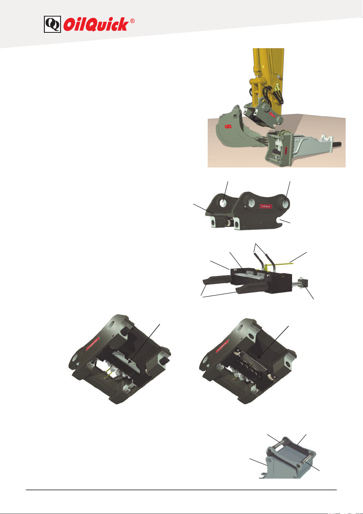
1. OilQuick quick coupler system components
The following section describes the various components in
the OilQuick quick coupler system.
1.1 Quick coupler body
1. Coupler body
2. For attaching to the excavator arm
3. For attaching to the linkage
4. Fingers
1
3
2
4
1.2 H-cylinder
5. H-cylinder
6. Cylinder holder
7. Hydraulic hoses for locking and unlocking
8 Locking plungers
9 Indicator rod
10. Dirt guard
10
Dirt guard closed Dirt guard open
8
5
10
7
9
6
10
1.3 Attachment frame for mechanical tools
11. Attachment
12. Front frame pin
13. Rear frame pin
14. Side part
Version 1.1 8 2011-06-28
11
14 12
13

1.4 Attachment frame for hydraulic tools
15. Attachment frame
16. Coupling ramp
17. Male connector
18. Front pin
19. Rear pin
The attachment frames are available in various models for different applications, but the function is the same
as for the basic model in each case. For further details, please contact your nearest OilQuick dealer.
17
18
15
19
16
1.5 V-90 electric coupling (option)
20. Contact socket
21. Contact plug
The contact elements are 10 pin.
21
20
21
20
1.6 1/2" electric coupling (option)
22. Contact socket
23. Contact plug
The contact elements are 10 pin.
22
23
22
23
1.7 Locking hydraulic kit (option)
28
24
27
26
24. Control switch with double command function
25. Alarm
26. Electric selector valve, 4/2
27. Cable set
28. Electric connection
Use this kit when a hydraulic lock has not yet been installed on the machine or OilQuick's requirements
for hydraulic locking has not been met (see section 3).
25
Version 1.1 9 2011-06-28
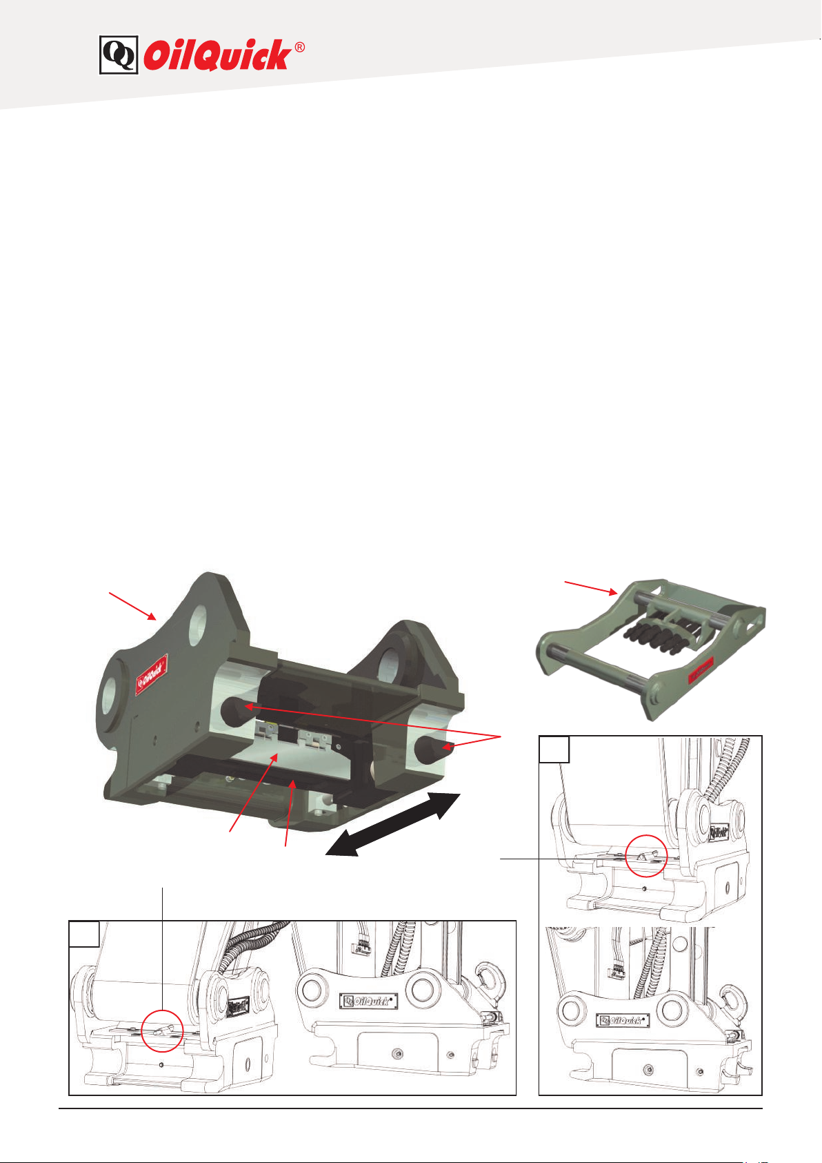
2. Quick coupler functionality
The quick coupler consists of a basic coupler part (1) with the H-cylinder (2) and various accessories
mounted on it. It is attached to the excavator arm and linkage. The H-cylinder (2) and locking plungers (3) are
moved backwards and forwards (4) when oil is supplied to the H-cylinder. When the H-cylinder is located at
the front position (4:1), the locking plungers are not visible and an attachment can be connected or disconnected. When the H-cylinder is located at the rear position (4:2), the locking plungers are visible and an attachment
frame can be connected to the coupler.
The hydraulic quick couplers are located in the middle of the H-cylinder between the locking plungers.
Models OQ 70/55 and OQ 80 can be fitted with two 1/2", two 3/4" and two 1" quick couplings.
A dirt guard (5) prevents the quick couplers from becoming dirty. It is opened automatically when the
H-cylinder is at the front position (4:1) and closed automatically at the H-cylinder's rear position (4:2).
The system installed on the excavator for the hydraulic quick coupler supplies oil to the H-cylinder (2).
The operator only has to take a look at the indicator rod (6) to check the H-cylinder's position.
When the indicator rod (6) is visible, the H-cylinder (2) is at its front position and the quick coupler is
unlocked. In this case an alarm sounds and a warning light comes on in the cab.
When the indicator rod (6) is not visible, the quick coupler is closed or locked with an attachment frame.
In this case there is no acoustic signal and the warning light does not come on.
When a hydraulic tool (7) is coupled, the hydraulic quick couplers are connected and the attachment is
mechanically locked.
1
4:1
6
5
2
4
7
3
4:2
6
Version 1.1 10 2011-06-28
 Loading...