

Oilon RE 35, RE 55, RE 70, RE 85, RE 42 Installation And Operation Manual
RE01 1445EN
Installation and operation manual
Oilon RE 35 – RE 85
Read these instructions carefully before installation, use, or maintenance


Contents
1. Introduction
1.1. Overview of this manual...............................................................................3
1.2. Transportation and storage.......................................................................... 3
1.3. Delivery content, optional equipment, and accessories............................... 4
1.4. Control system.............................................................................................. 5
1.5. Operating principle........................................................................................6
1.6. Main features................................................................................................ 7
1.7. Heat pump system dimensioning................................................................. 8
1.8. Collecting heat.............................................................................................. 8
2. Installation
2.1. Installation site requirements........................................................................9
2.2. Main components........................................................................................11
2.3. Connections and dimensions..................................................................... 14
2.4. Piping diagrams.......................................................................................... 17
2.5. Electrical connections................................................................................. 23
2.6. Filling brine circuit.......................................................................................25
2.7. Filling heating network................................................................................27
3. Commissioning
3.1. Fuses and switches.................................................................................... 28
3.2. Prerequisites for commissioning.................................................................28
3.3. Commissioning the system.........................................................................28
3.4. Testing relay............................................................................................... 29
3.5. Adding heating circuits............................................................................... 30
3.6. Configuring heating curve...........................................................................30
3.7. Connecting solar heating............................................................................34
4. Operation
4.1. Control panel...............................................................................................36
4.2. Changing settings....................................................................................... 38
4.3. Changing user level....................................................................................40
4.4. Setting language......................................................................................... 40
4.5. Setting time and date................................................................................. 40
4.6. Configuring domestic hot water settings.................................................... 40
4.7. Operating lines............................................................................................41
5. Maintenance
5.1. Annual maintenance................................................................................... 47
5.2. Cleaning the circuit filter.............................................................................47
5.3. Troubleshooting...........................................................................................47
RE01 1445EN 1 (67)

6. Technical data
6.1. Heat pump technical data...........................................................................51
6.2. Condenser and ground circuit flow and pumps..........................................52
6.3. Spare parts................................................................................................. 62
2 (67) RE01 1445EN
1. Introduction
1.1. Overview of this manual
Keep the instructions near the device.
Read these instructions carefully before installing, adjusting or maintenance of the
device. Follow the given instructions.
Remember to ask the HVAC technician to fill in the installation record, which is
returned to heat pump manufacturer. The installation record is a prerequisite for the
manufacturer’s guarantee.
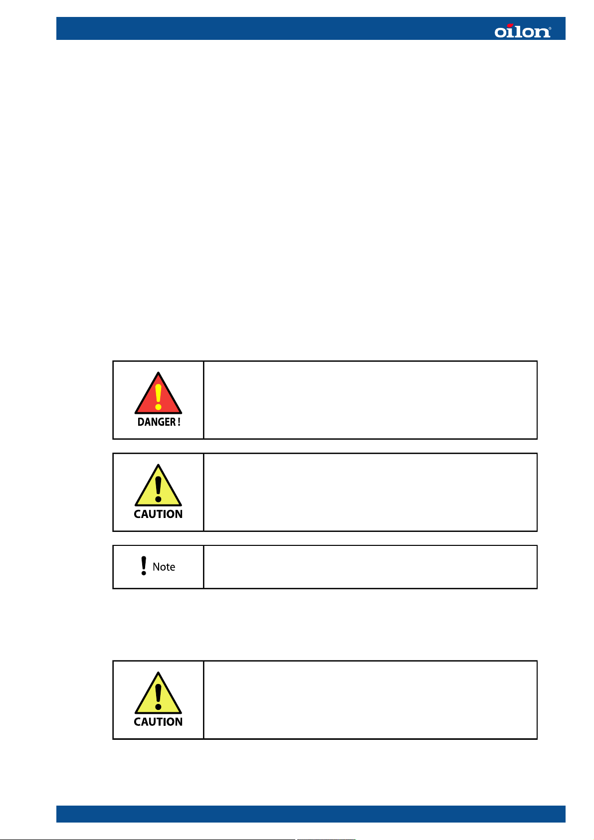
Warnings
Throughout this manual, the following warnings are used to point out information:
Be careful. The symbol indicates a possible danger of bodily
harm or lethal injury if instructions are not followed.
Pay attention. The symbol indicates a possible danger
of damage to the device, components or surroundings if
instructions are not followed.
Read this instruction. Note indicates important information.
1.2. Transportation and storage
Transport and store the heat pump in a vertical position.
Transport the heat pump to the installation site on its
transporting platform.
RE01 1445EN 3 (67)

Be careful when lifting the heat pump. Use appropriate lifting
tools.
The heat pump can be tilted to a maximum angle of 45 degrees
for short periods of time (1–2 minutes).
Always use a pallet truck when lifting the RE 55, RE 70, and RE 85 heat pumps. The
smaller models RE 35 and RE 42 you can also lift and move with a hand truck.
When using a hand truck, lift the heat pump only from the back or front of the device.
1.3. Delivery content, optional equipment, and accessories
Standard delivery content
Heat pump standard delivery includes the following:
● heat pump
● condenser circuit pump
● ground circuit pump
● outdoor temperature sensor
● space heating circuit temperature sensor
● 3 temperature sensors for buffer tank *)
● installation and operation manual, electrical drawings
● installation, commissioning and warranty records
● maintenance sheets.
*) By default, 2 temperature sensors have been configured as space heating buffer
tank temperature sensors, and 1 for domestic hot water buffer tank temperature
sensor. Settings can be changed in commissioning.
Optional equipment
In addition to the standard delivery content, the following optional equipment may be
separately ordered:
● buffer tanks
● desuperheater package, which includes heat exchanger, circulation pump, and
connection hose package for desuperheater model 1 ¼” 1000 mm (4 steel cord
hoses + gaskets)
● Modbus gateway
● remote control unit for monitoring device through LAN, Internet, and SMS
● remote control unit for monitoring device through LAN, Internet, smart phone
application, and ACS computer program
● wireless or wired control unit
● wireless or wired room temperature and outdoor temperature sensor
● signal amplifier for wireless devices
4 (67) RE01 1445EN

● humidity sensors for cooling applications
● diverting valve
● connection hose package 2” 1000 mm (4 steel cord hoses + gaskets)
Accessories
When installing the heat pump, depending on the installation site, few additional
accessories and devices may be needed. Among other things, the following
accessories may be ordered separately:
● ground circuit diaphragm expansion tank
● ground circuit safety valve
● heating circuit diaphragm expansion tank
● heating circuit 3- or 4-way valves
● heating system expansion tank
● pump for heating circuits 1, 2 and 3
● mixing valve for domestic hot water
● heating system safety valve (1,5 bar)
● heating system pressure gauge (0–4 bar)
● ground circuit pressure gauge (0–4 bar)
● filters for ground circuit and heating circuit
● flexible connection hoses for brine and condenser circuits with seals
● pipes and pipe accessories.
1.4. Control system
The heat pump is equipped with an automatic control system which manages heating
and domestic hot water production. The control system includes the built-in automation
system, the sensors attached to it, and a control panel. The control panel is used for
monitoring and changing system settings. Also error notifications are browsed and
reset on the control panel.
An optional remote control unit can also be used for browsing and changing system
data and error notifications. It can also serve as a remote temperature sensor,
providing the control system with room temperature data.
The heat pump can be remotely controlled and monitored through Modbus gateway
and remote access modules.
The system settings have been organized into menus, similar to folders on a computer.
In addition, there are various user levels in the system. The visibility of menus or
menu items depends on the user level. To access user levels other than End user or
Commissioning, an access code is needed.
RE01 1445EN 5 (67)

1.5. Operating principle
A
B
C
RE15 ver. 2
1. Evaporator
2. Compressor
3. Condenser
4. Expansion valve
There are three closed circuits running within, or through, the heat pump:
● brine circuit
● refrigerant circuit
● heating circuit.
The heat pump's operation is based on the vaporisation and condensation of the
refrigerant circulating within the heat pump.
The brine circuit is a circuit for collecting heat energy from the ground. When the brine
enters to the circuit at the evaporator, it is very cold. As it travels along the circuit, it
collects heat energy from the ground or water, which causes the brine temperature
to rise. The brine completes its circuit by returning to the evaporator and releasing
the heat energy into the refrigerant, which circulates between the evaporator and the
condenser.
When the refrigerant is in the condenser, it is colder than the brine, so the heat
energy transfer from brine into refrigerant can take place. The heat transfer raises the
temperature of the refrigerant up to the point where it becomes gaseous.
A. Brine circuit
B. Refrigerant circuit
C. Heating circuit
6 (67) RE01 1445EN
The gaseous refrigerant is then led into a compressor, which compresses it into a
high pressure. As the pressure of the gaseous refrigerant increases, so does its
temperature.
Next, the high-pressure gaseous refrigerant is led into the condenser, where it releases
its heat energy into the water that circulates between the heat pump and the buffer
tank. As the refrigerant releases its heat energy and its temperature drops, it becomes
liquid again.
The liquid refrigerant is then led into an expansion valve, where the pressure and
temperature are lowered further. The refrigerant completes its circuit by returning back
to the evaporator, where it receives heat energy from the brine circuit.
The heat pump can also be used as a water chiller.
1.6. Main features
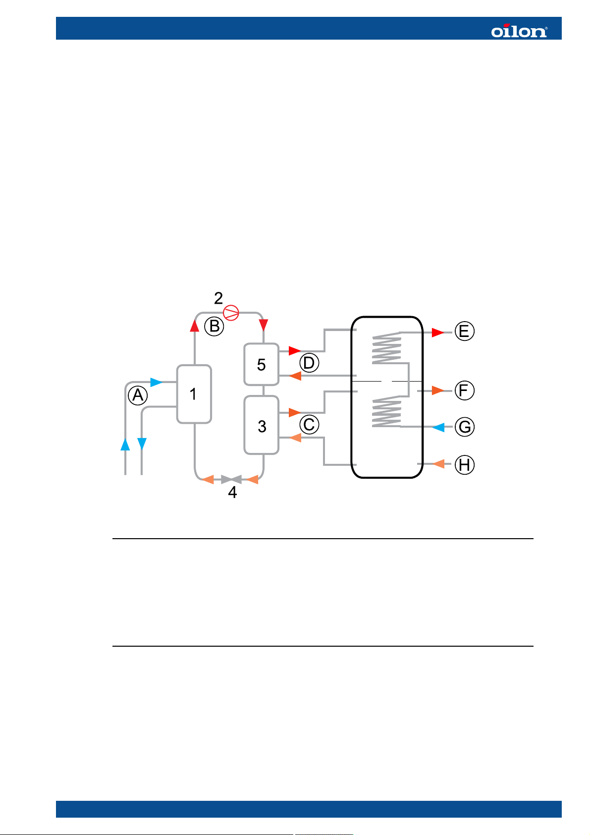
The following figure represents a principle of the RE heat pump connections. For more
detailed instruction about connections, see section Piping diagrams.
RE16 ver. 1
1. Evaporator
2. Compressor
3. Condenser
4. Expansion valve
5. Desuperheater (option)
A. Brine circuit
B. Refrigerant circuit
C. Condenser circuit
D. Desuperheater circuit
E. Domestic hot water
F. Heating circuit out
G. Domestic cold water
H. Heating circuit in
The RE heat pump is always connected to a separate buffer tank or buffer tanks.
Domestic hot water is warmed up in hot water loops inside buffer tank. Preheating loop
can be located in the middle of the same buffer tank or in another buffer tank. Rest of
the heating is carried out by loop in the upper part of the buffer tank or loop in separate
domestic hot water buffer tank.
For all RE heat pumps, the desuperheater functionality can be ordered as an option.
RE01 1445EN 7 (67)

When using the heat pump as a water chiller (clean water circulates in the evaporator
instead of frost-proof solution), the evaporator must be protected from freezing. Usage
of flow switch on the evaporator side is highly recommended.
When maintaining the heat pump, note that adding and purging of a liquid refrigerant
from the evaporator with standing water can cause a frost damage.
1.7. Heat pump system dimensioning
Ground source heat pump can be sized to operate at
● partial capacity
● full capacity.
With partial capacity heat pump maximum capacity is sized up to correspond 60 – 80%
of a building’s maximum heating demand. In this case the heat pump produces the
most part of the building’s annual heat energy demand.
With partial capacity, heat pump operating periods are long during heating season.
This reduces the number of compressor stops and start-ups. During hardest freezing
periods at winter additional capacity from heat pump can be obtained with in-built
electric heater or oil boiler.
With full capacity, heat pump is sized up according to a building’s maximum capacity
demand, practically slightly over sized. With full capacity, the use of additional heating
capacity is minimised, thus in electric heaters’ case it is possible to use smaller fuse
size in electrical connection.
1.8. Collecting heat
Oilon RE heat pump’s heat source is usually a drilled well. The number and depth of
wells depend on heating demand. Soil or water can also be used as heat source. When
using water the piping is anchored to the bottom.
During heating period, the ground circuit fluid warms up a few degrees during
circulation. Collected heat is used to vaporise refrigerant in heat pump unit. Horizontal
piping requires applicable soil type and sufficient land area for piping. Applicable soil
types are fine grained and moist, such as clay or silt. Drilled well is suitable for all
locations except places where solid rock goes deep underground. When piping is
installed into water, building should be located sufficiently close to shoreline, preferably
less than 50 m away. Water should also be sufficiently deep, over 2 m right from shore.
In addition, waste heat from industrial processes can be used as heat source for the
heat pump.
8 (67) RE01 1445EN
2. Installation
2.1. Installation site requirements
Installation, commissioning or service of equipment must be
carried out by authorized personnel only, adhering to all local
regulations and requirements.
General site requirements
When installing the heat pump, note the following recommendations and requirements:
● The installation site must have a floor drain.
● Site temperature must be between 10 °C – 40 °C.
● Install the heat pump on an even surface and make sure it is horizontal. You can
adjust the level with the housing screws on the bottom of the heat pump.
● Make sure the flooring is able to withstand its weight.
● Make sure that the heat pump does not touch any wall.
● The heat pump is covered against moisture and water.
● The installation site should ideally be separate from the common living area so that
it is easier to contain noise.
Space requirements
All heat pump connections are at the back of the device and with flexible hoses they
can be bent to desired directions. Always use flexible hoses when connecting the pump
to piping to retain the warranty. For installation, operating and maintenance purposes,
leave enough space on each side of the heat pump. The minimum space requirements
are presented in the following.
RE01 1445EN 9 (67)
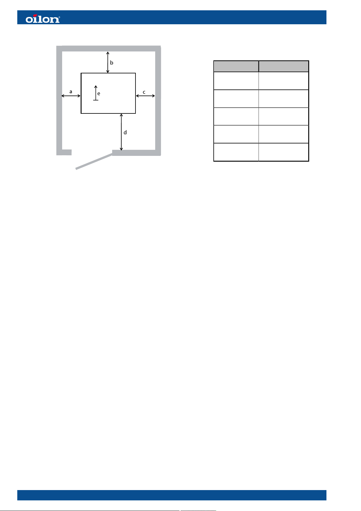
Legend RE 35 – RE 85
RE01 ver. 2
a
(left)
b
(back)
c
(right)
d
(front)
e
(top)
500 mm
500 mm
100 mm
1000 mm
500 mm
10 (67) RE01 1445EN
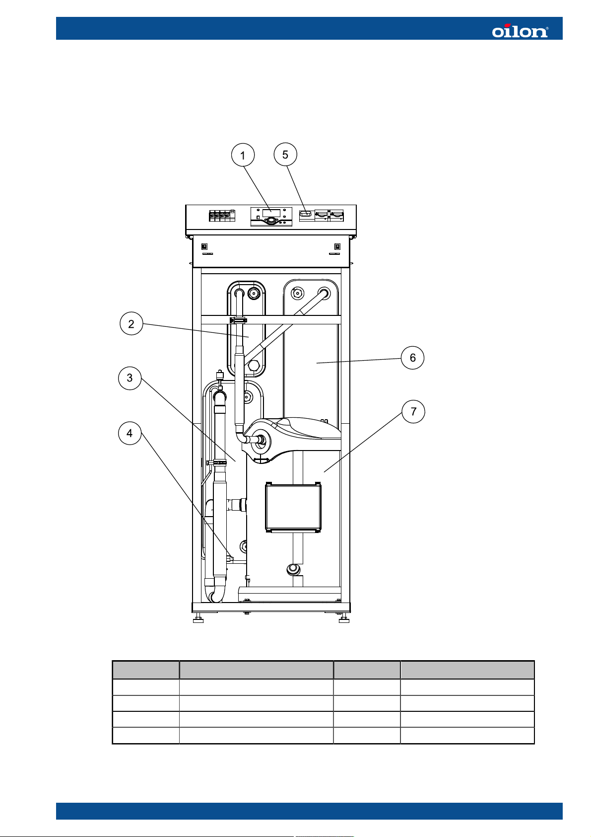
2.2. Main components
RE 35 and RE 42
RE35-42 ver. 1
Legend Part Legend Part
1 Control panel 5 Main electrical switch
2 Desuperheater 6 Condenser
3 Evaporator 7 Compressor
4 Expansion valve
RE01 1445EN 11 (67)
40
40
40
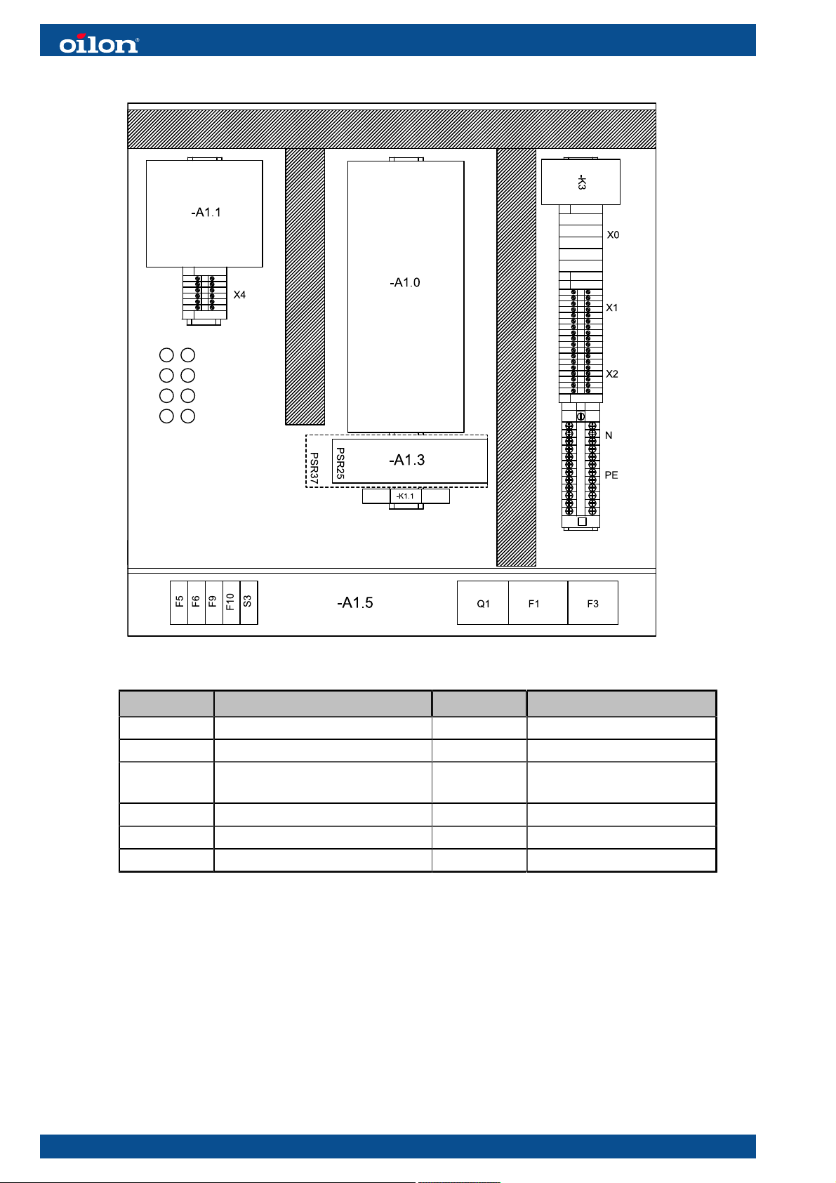
RE35-42CP ver. 1
Legend Part Legend Part
A1.0 Heat pump controller F1 Auxiliary contact
A1.1 Auxiliary module F3 Motor circuit breaker
A1.3 Softstarter F5, F6, F9,
F10
Line protection circuit
breaker
A1.5 Operation unit S3 Control switch
K1.1 Relay Q1 Load break switch
K3 Contactor
12 (67) RE01 1445EN
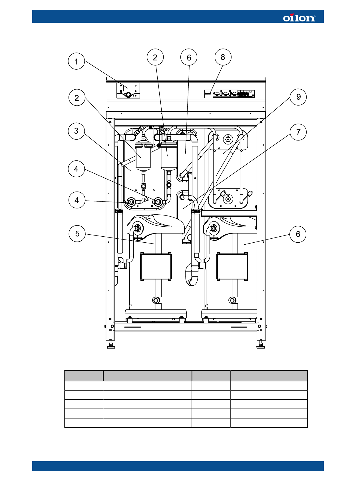
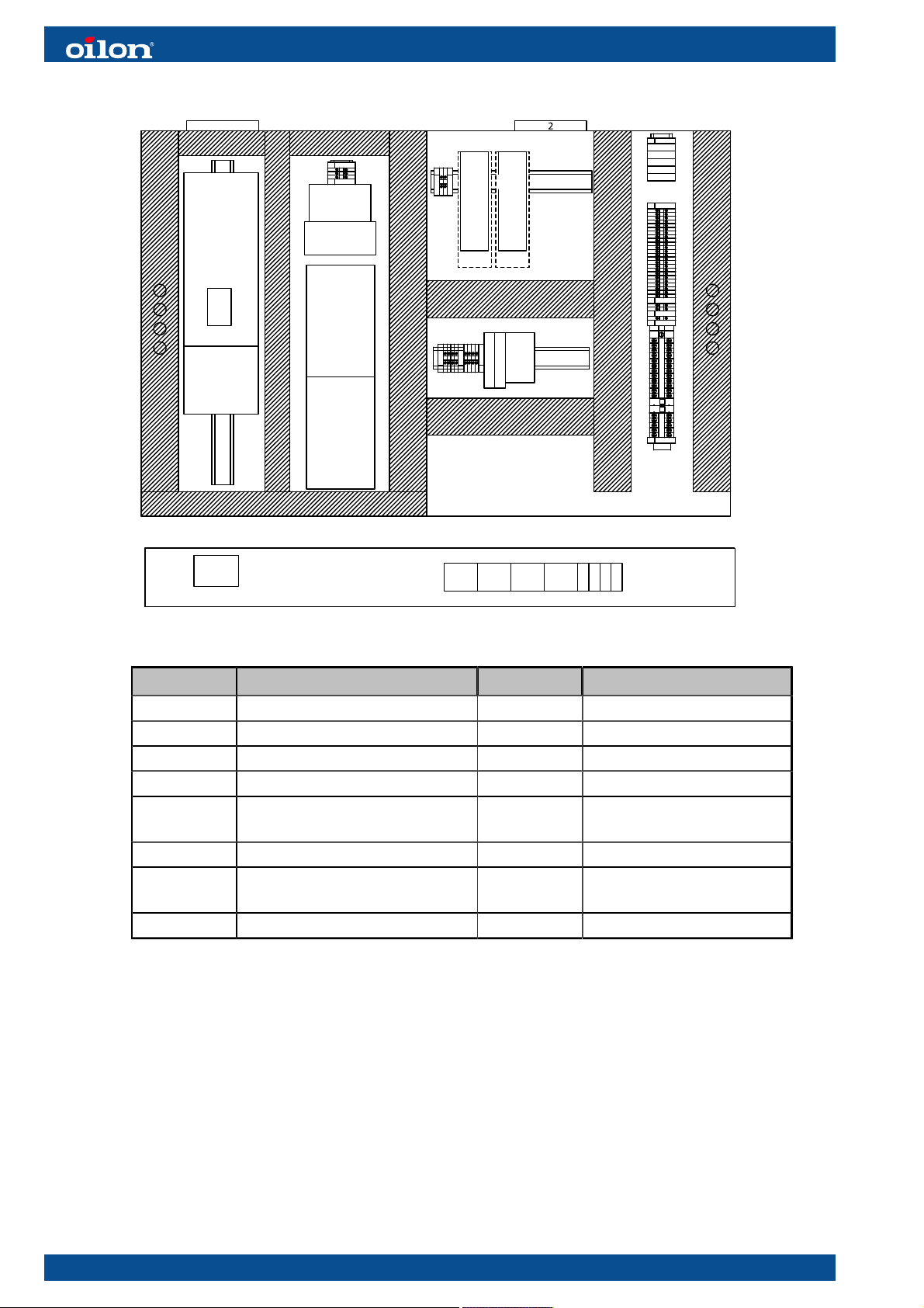
RE 55, RE 70, and RE 85
RE55-85002 ver. 1
Legend Part Legend Part
1 Control panel 6 Compressor 2
2 Dryer-filter 7 Desuperheater
3 Evaporator 8 Main electrical switch
4 El. expansion valve 9 Condenser
5 Compressor 1
RE01 1445EN 13 (67)
Q1
-F6.1
N
F3
F1
F2
F5F6S3
F9
60
60
60
X1
X0
X2
PE
40
-K2.1
60
-A1.9
60
-A1.1
-A1.0
40
-A2.3
-A2.4
PSR25
PSR37
-A1.4
-A1.3
-K1.1
-K3
X4
X5
40
-U6
40
-G6
-F2.3
-F2.4
60
PE
X4
-A1.5
-E1
RE55-85CP ver. 1
Legend Part Legend Part
E1 Fan A1.3, A1.4 Softstarter
2 Filter K1.1, K2.1 Relay
A1.0 Heatpump controller K3 Contactor
A1.1 Auxiliary module A1.5 Operation unit
F2.3, F2.4,
F6.1
U6 UPS module F1, F2, F3 Motor circuit breaker
G6 DC source F5, F6, F9 Line protection circuit
A2.3, A2.4 Superheat controller S3 Control switch
2.3. Connections and dimensions
Fused terminal Q1 Load break switch
breaker
For information on connection positions and sizes, see the following illustration.
14 (67) RE01 1445EN
RE 35 and RE 42
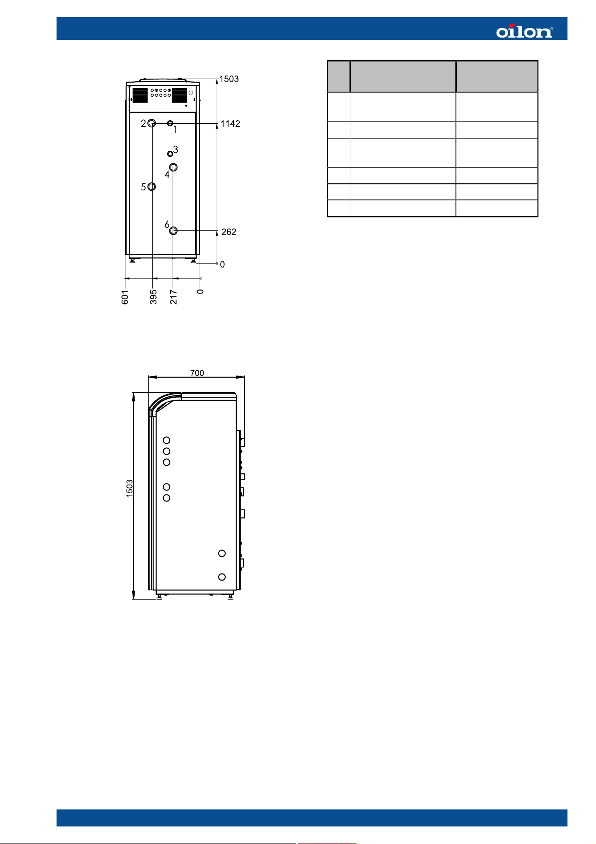
Connection Size (external
thread)
1 Desuperheater out
(optional)
2 Condenser out G 2
3 Desuperheater in
(optional)
4 Evaporator in G 2
5 Condenser in G 2
6 Evaporator out G 2
RE07 ver. 3
For information on sizes from the side, see the following illustration.
G 1 1/4
G 1 1/4
RE08 ver. 1
RE 55, RE 70, and RE 85
For information on connection positions and sizes, see the following illustration.
RE01 1445EN 15 (67)
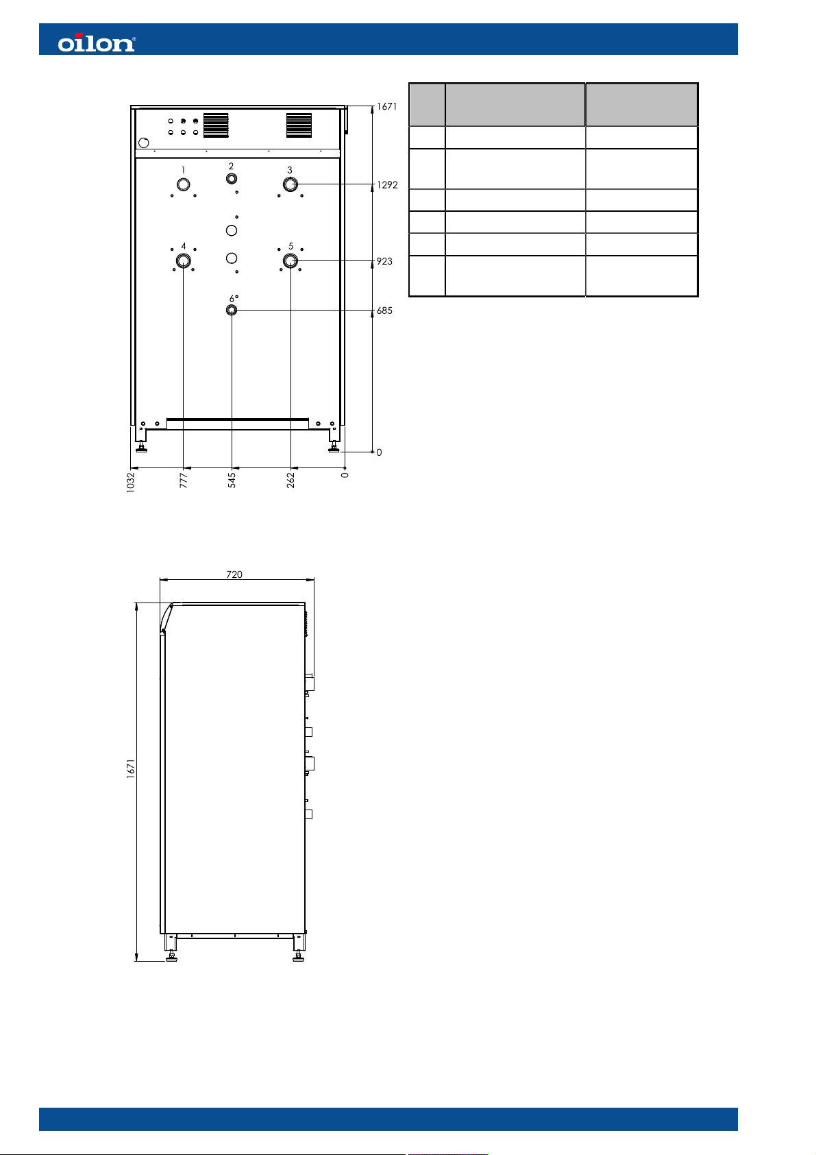
Connection Size (external
thread)
1 Condenser out G 2
2 Desuperheater out
G 1 1/4
(optional)
3 Evaporator in G 2
4 Condenser in G 2
5 Evaporator out G 2
6 Desuperheater in
G 1 1/4
(optional)
RE02 ver. 2
For information on sizes from the side, see the following illustration.
RE03 ver. 1
16 (67) RE01 1445EN
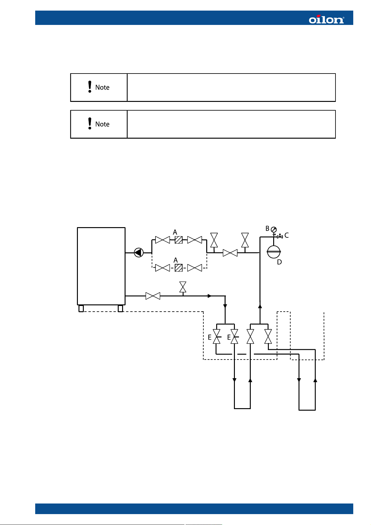
2.4. Piping diagrams
A filter should always be installed on both the heating circuit
return line and the brine circuit return line before the heat pump.
Install a shut-off valve on both sides of the filter to facilitate easy
cleaning and replacing of the filter element.
2.4.1. Ground circuit piping
We recommend to install the line regulation valves with flow meters, shut-off valves
and pressure gauge as shown in the following figure. If there is a risk that the ground
circuit pipes are not clean, install two filters to the return line to ensure fluent flow.
RE04 ver. 2
A filters
B pressure gauge
C safety valve
D expansion tank
E line regulating valve with flow meter
RE01 1445EN 17 (67)
Make an approximately 1 m deep service well on top of the heat well. Connect the
service wells to one shared collector well using insulated pipes. One of the drilled wells
can also operate as a collector well. Fluid from collector well is led to the heat pump
well through two insulated pipes.
The minimum pipe diameters for the collector well are listed in the following table.
Model Pipe diameter
RE 35, RE 42 and RE 55 63 mm
RE 70 and RE 85 75 mm
2.4.2. Heating circuit piping
Some examples of heating circuit piping options are presented in the following.
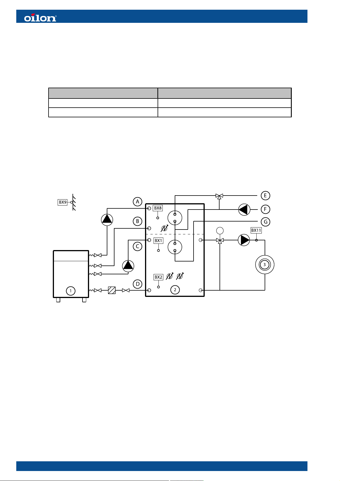
Heat pump with desuperheater and buffer tank
PI RE ver. 6
1 heat pump A desuperheater out
2 buffer tank B desuperheater in
3 heating circuit C condenser out
BX11temp.sensor, supply water D condenser in
BX1 temp.sensor, buffer tank middle part E domestic hot water out
BX2 temp.sensor, buffer tank lower part F domestic hot water circulation
BX8 temp.sensor, buffer tank upper part G domestic cold water in
BX9 temp.sensor, outdoors
18 (67) RE01 1445EN
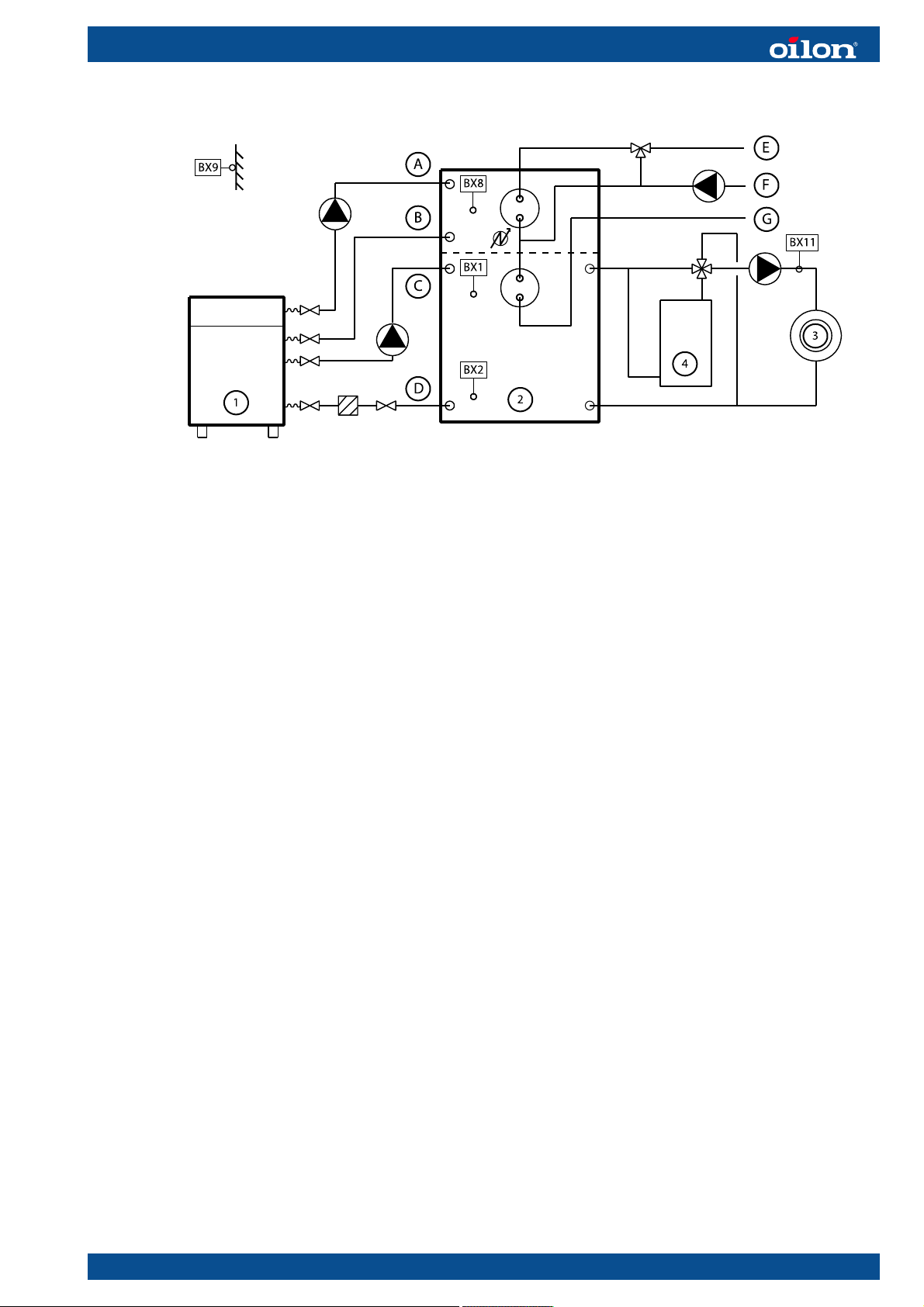
Heat pump with desuperheater, buffer tank and extra heating system
PI RE 1 ver. 6
1 heat pump A desuperheater out
2 buffer tank B desuperheater in
3 heating circuit C condenser out
4 extra heating system, e.g. electric or
D condenser in
oil heater
BX11temp.sensor, supply water E domestic hot water out
BX1 temp.sensor, buffer tank middle part F domestic hot water circulation
BX2 temp.sensor, buffer tank lower part G domestic cold water in
BX8 temp.sensor, buffer tank upper part
BX9 temp.sensor, outdoors
RE01 1445EN 19 (67)
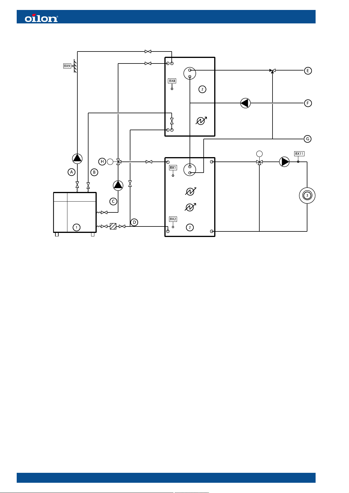
Heat pump with desuperheater and two external buffer tanks
PI RE 2 ver. 7
1 heat pump A desuperheater out
2 buffer tanks B desuperheater in
3 heating circuit C condenser out
BX11temp.sensor, supply water D condenser in
BX1 temp.sensor, buffer tank middle part E domestic hot water out
BX2 temp.sensor, buffer tank lower part F domestic hot water circulation
BX8 temp.sensor, domestic hot water
G domestic cold water in
buffer tank
BX9 temp.sensor, outdoors H diverting valve
20 (67) RE01 1445EN
 Loading...