

Oilon GT 5, GT 28, SH 7, GT 7, GT 9 Operation Manual
...
GT02 1408 EN
Operation manual
GT 5 - GT 28
Read these instructions carefully before installation, use, or maintenance


GT02 1408 EN 1 (24)
Contents
1. Introduction
1.1. Warnings....................................................................................................... 3
1.2. Transportation and storage.......................................................................... 3
1.3. Delivery content, optional equipment and accessories................................ 4
1.4. Ground source heat pump operating principle............................................. 5
1.5. Ground source heat pump sizing................................................................. 6
2. Operation
2.1. Control system.............................................................................................. 7
2.2. Control panel.................................................................................................7
2.3. Changing settings....................................................................................... 10
2.4. Changing user level....................................................................................11
2.5. Setting language......................................................................................... 11
2.6. Setting time and date................................................................................. 11
2.7. Configuring heating curve...........................................................................12
2.8. Configuring domestic hot water settings.................................................... 13
2.9. Changing heating mode and domestic hot water heating.......................... 13
2.10. Performing forced charging........................................................................ 13
2.11. Resetting alarms and failures.....................................................................14
2.12. Configuring electric heater settings............................................................ 14
2.13. Adding heating circuits............................................................................... 14
2.14. Saving new default settings........................................................................15
2.15. Adjusting room temperature with remote controller....................................15
2.16. Operating lines............................................................................................15
3. Maintenance
3.1. Cleaning the brine circuit filter....................................................................21
3.2. Operating ground source heat pump manually.......................................... 21
3.3. Troubleshooting...........................................................................................21
4. Technical data
4.1. Technical data.............................................................................................23

2 (24) GT02 1408 EN
GT02 1408 EN 3 (24)
1. Introduction
1.1. Warnings
KEEP THE OPERATION MANUAL NEAR THE DEVICE!
Read these instructions carefully before using, adjusting or maintenance of the device.
Follow the given instructions.
Remember to ask the HVAC technician to fill in the installation record, which is
returned to heat pump manufacturer. The installation record is a prerequisite for the
manufacturer’s guarantee.
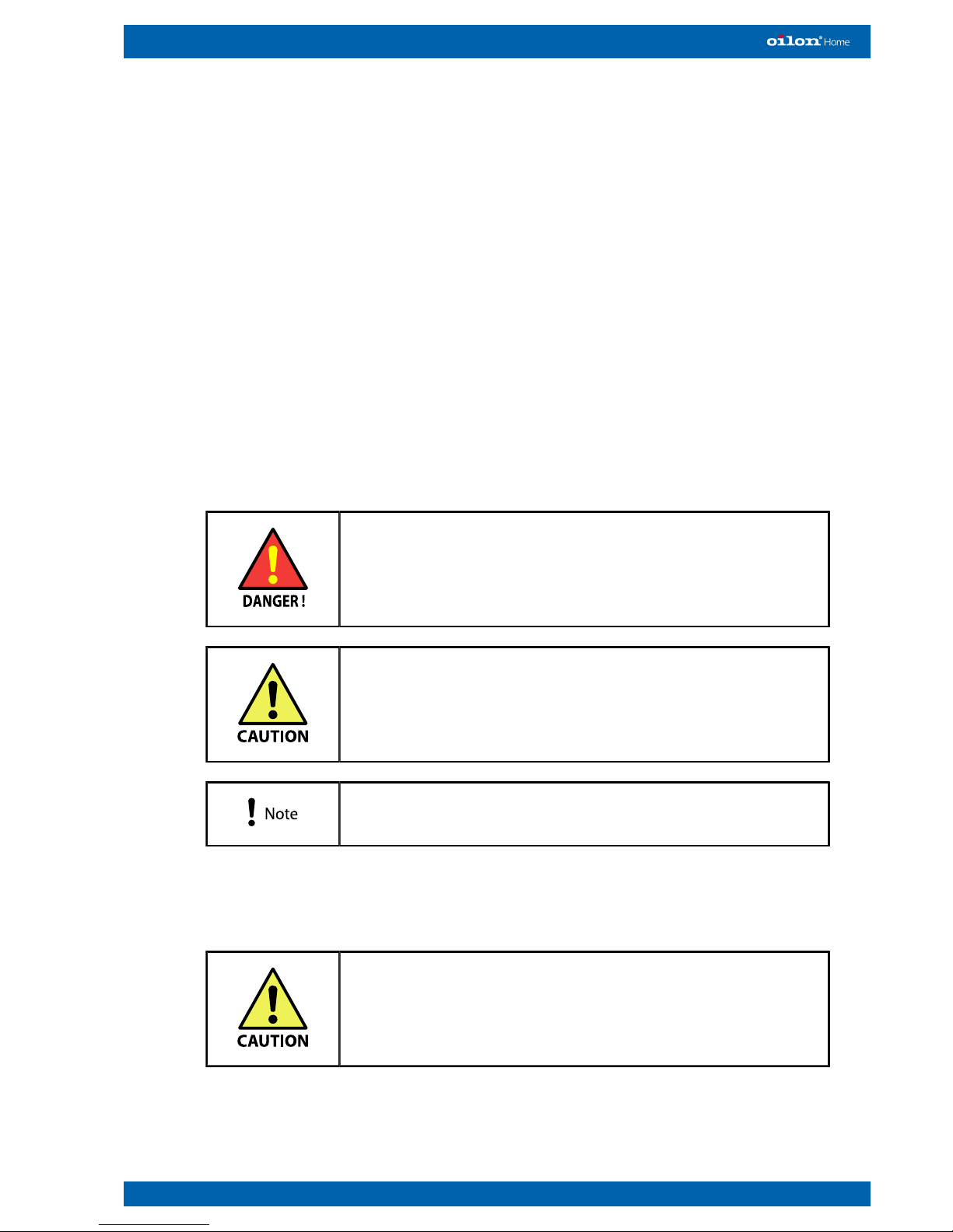
Throughout this manual, the following warnings are used to point out information:
Be careful. The symbol indicates a possible danger of bodily
harm or lethal injury if instructions are not followed.
Pay attention. The symbol indicates a possible danger
of damage to the device, components or surroundings if
instructions are not followed.
Read this instruction. Note indicates important information.
1.2. Transportation and storage
Transport and store the heat pump in a vertical position.
Transport the heat pump to the installation site on its
transporting platform.
If necessary, you can remove the platform and move the heat pump using a hand
truck. Use the hand truck to lift the heat pump only from the back of the device.

4 (24) GT02 1408 EN
The heat pump can be tilted to a maximum angle of 45 degrees
for short periods of time (1–2 minutes).
1.3. Delivery content, optional equipment and accessories
Standard delivery content
Heat pump standard delivery includes the following:
● heat pump
● condenser pump
● ground circuit pump
● temperature sensor for outdoors
● 2 temperature sensors for supply water
● 2 temperature sensors for buffer tank
● installation and operation manual, electrical drawings
● installation, commissioning and warranty records
● maintenance sheets.
Optional equipment
In addition to the standard delivery content, the following optional equipment may be
separately ordered:
● wired or wireless remote control unit, including room temperature sensor
● Smartweb connection.
Accessories
When installing the heat pump, depending on the installation site, few extra
accessories and devices maybe needed. Among other things, the following
accessories may be separately ordered:
● ground circuit diaphragm expansion tank
● ground circuit safety valve
● heating circuit diaphragm expansion tank
● heating circuit 3 or 4-way valves
● electric cables needed outside the heat pump
● heating system expansion tank
● pump for heating circuits 1, 2 and 3
● mixing valve for domestic hot water
● heating system safety valve (1,5 bar)
● heating system pressure gauge (0–4 bar)
● ground circuit pressure gauge (0–4 bar)
● filters for ground circuit and heating circuit
● flexible connection hoses for brine and condenser circuits with seals
● pipes and pipe accessories.
GT02 1408 EN 5 (24)
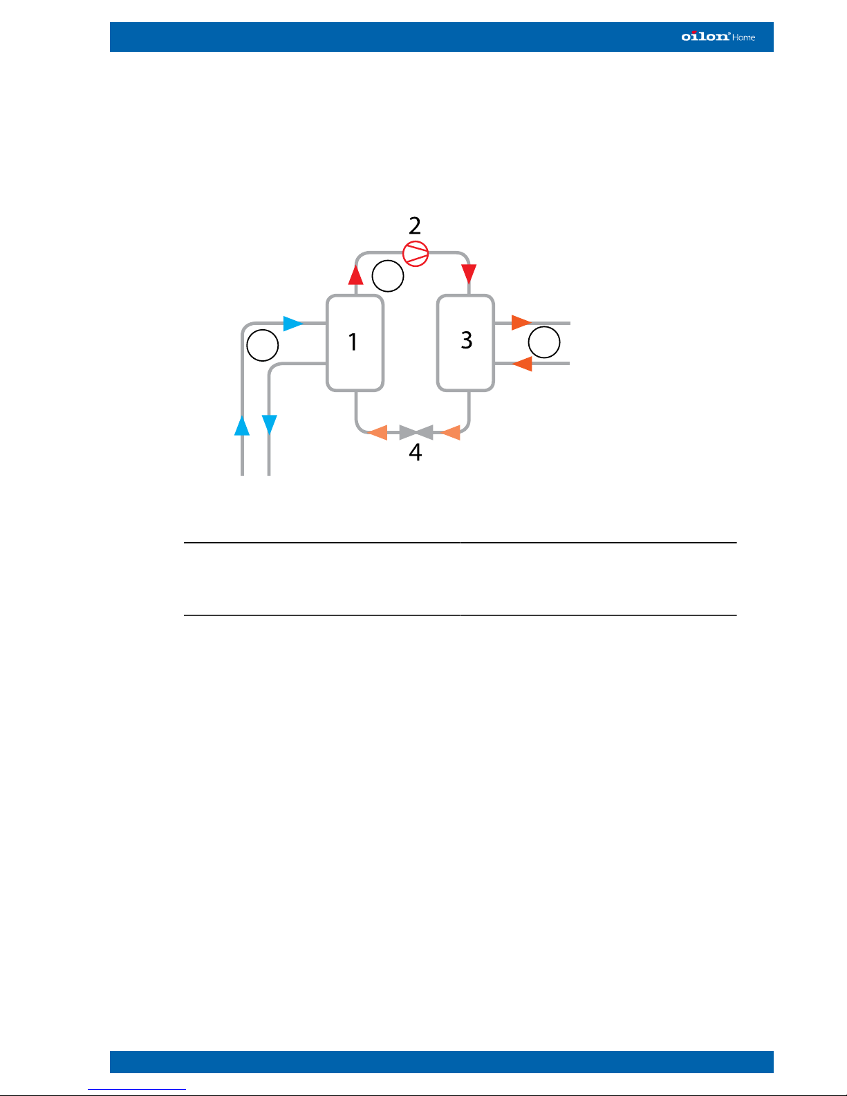
1.4. Ground source heat pump operating principle
A ground source heat pump is a device that uses heat energy from the Sun that is
absorbed into Earth’s surface.
A
B
C
RE15 ver. 2
1. Evaporator
2. Compressor
3. Condenser
4. Expansion valve
A. Brine circuit
B. Refrigerant circuit
C. Heating circuit
There are three closed circuits running within, or through, the heat pump:
● brine circuit
● refrigerant circuit
● heating circuit.
The heat pump's operation is based on the vaporisation and condensation of the
refrigerant circulating within the heat pump.
The brine circuit is a circuit for collecting heat energy from the ground. When the brine
enters to the circuit at the evaporator, it is very cold. As it travels along the circuit, it
collects heat energy from the ground or water, which causes the brine temperature
to rise. The brine completes its circuit by returning to the evaporator and releasing
the heat energy into the refrigerant, which circulates between the evaporator and the
condenser.
When the refrigerant is in the condenser, it is colder than the brine, so the heat
energy transfer from brine into refrigerant can take place. The heat transfer raises the
temperature of the refrigerant up to the point where it becomes gaseous.
The gaseous refrigerant is then led into a compressor, which compresses it into a
high pressure. As the pressure of the gaseous refrigerant increases, so does its
temperature.

6 (24) GT02 1408 EN
Next, the high-pressure gaseous refrigerant is led into the condenser, where it releases
its heat energy into the water that circulates between the heat pump and the buffer
tank. As the refrigerant releases its heat energy and its temperature drops, it becomes
liquid again.
The liquid refrigerant is then led into an expansion valve, where the pressure and
temperature are lowered further. The refrigerant completes its circuit by returning back
to the vaporiser, where it receives heat energy from the brine circuit.
1.5. Ground source heat pump sizing
Ground source heat pump can be sized to operate at
● partial capacity
● full capacity.
With partial capacity heat pump maximum capacity is sized up to correspond 60 – 80%
of a building’s maximum heating demand. In this case the heat pump produces the
most part of the building’s annual heat energy demand.
With partial capacity, heat pump operating periods are long during heating season.
This reduces the number of compressor stops and start-ups. During hardest freezing
periods at winter additional capacity from heat pump can be obtained with in-built
electric heater or oil boiler.
With full capacity, heat pump is sized up according to a building’s maximum capacity
demand, practically slightly over sized. With full capacity, the use of additional heating
capacity is minimised, thus in electric heaters’ case it is possible to use smaller fuse
size in electrical connection.
GT02 1408 EN 7 (24)
2. Operation
2.1. Control system
The heat pump is equipped with an automatic control system which manages heating
and domestic hot water production. The control system includes the built-in automation
system, the sensors attached to it, and a control panel. Browsing and changing system
settings is done on the control panel. It is also used for browsing and resetting error
notifications.
A remote control unit (option) can also be used for browsing and changing system
data and error notifications. The remote control unit can also be used as a remote
temperature sensor, providing the control system with room temperature data.
The system settings have been organised into menus, similar to folders on a computer.
In addition, there are various user levels in the system. The visibility of menus or
menu items depends on the user level. To access user levels other than End user or
Commissioning, you need an access code.
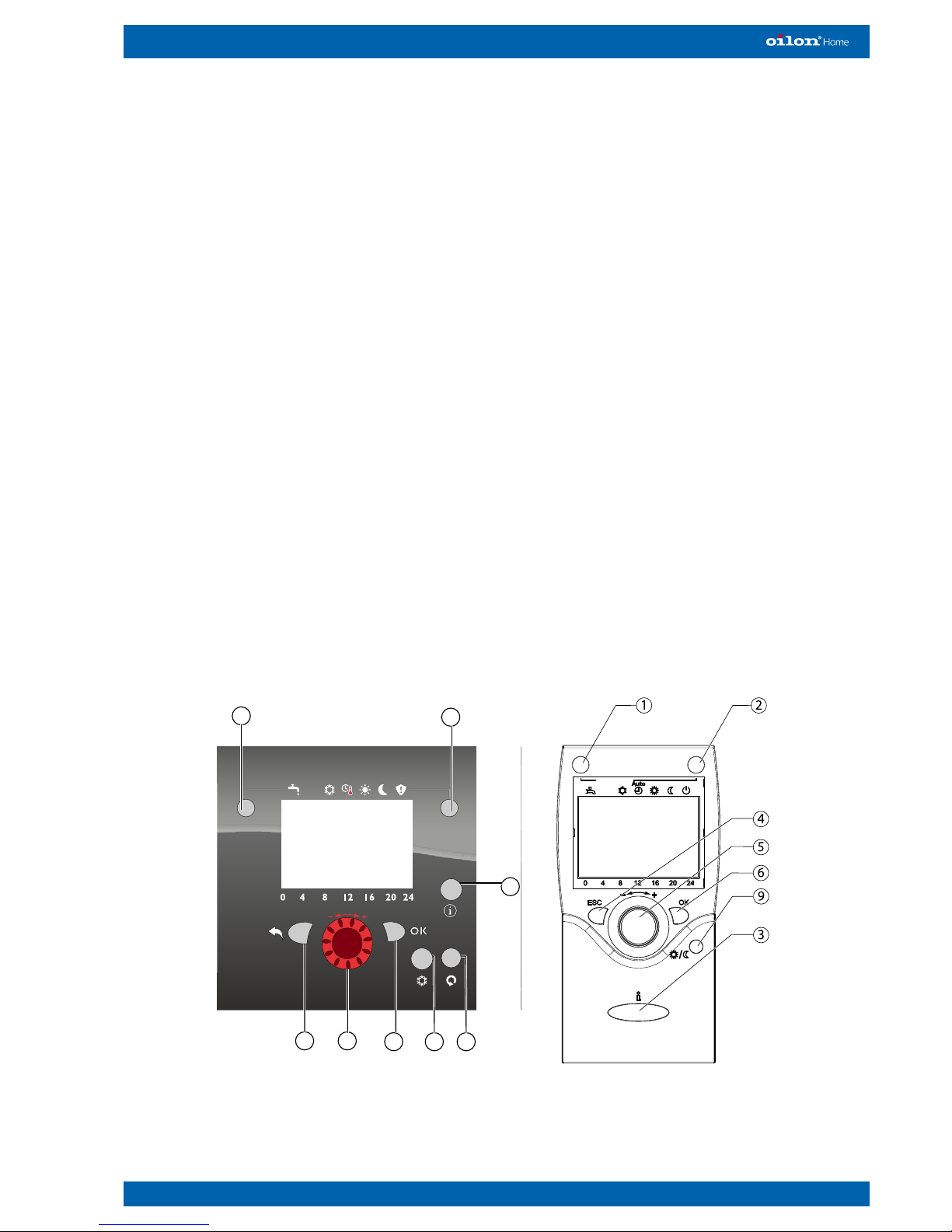
2.2. Control panel
Control panel Remote controller
(optional extra)
1
4
5
6 87
2
3
Control panel ver. 3
GSHP01 ver. 3
 Loading...