

Oilon GP-6.10 P, GP-6.20 P Maintenance Manual

OPERATING AND MAINTENANCE
INSTRUCTIONS
GAS BURNERS
q GP-6.10 P
q GP-6.20 P
OILON OY
P.O.Box 5
FIN-15801 LAHTI FINLAND
Tel. +358 3 85 761
Fax +358 3 857 6239
E-mail info@oilon.com 40180036GB


Table of Contents
1. Conventions in this Manual ............................................................................................................1
2. General...........................................................................................................................................2
3. Burner Technical Data ...................................................................................................................4
3.1. Technical Data .....................................................................................................................4
3.2. Basic Assembly Drawing......................................................................................................5
3.3. Parts List ..............................................................................................................................6
3.4. Burner Dimensions ..............................................................................................................6
3.5. Nozzle Table ........................................................................................................................6
4. Burner Installation ..........................................................................................................................7
4.1. Burner Mounting...................................................................................................................7
4.2. Hinged Burner Housing........................................................................................................7
4.3. Electric Connections ............................................................................................................7
4.4. Example of an Installation of Gas Supply Line ....................................................................8
4.5. Gas Pressure Regulating Assembly ....................................................................................9
5. Burner Automation .......................................................................................................................10
5.1. Time Sequence Diagram (High-Low) ................................................................................10
5.2. Time Sequence Diagram (Modulating) ..............................................................................11
5.3. Operation ...........................................................................................................................12
6. Burner Adjustments......................................................................................................................15
6.1. Capacity Regulation ...........................................................................................................15
6.2. PI-Diagram.........................................................................................................................16
6.3. Combustion Head Adjustments .........................................................................................17
6.3.1. Distance between Nozzle and Diffuser Disc and Ignition Electrode
Setting ...................................................................................................................17
6.3.2. Adjusting the Air Velocity in the Combustion Head ...............................................17
6.3.3. Setting Values of Adjustment Ring........................................................................18
6.4. Combustion Air Adjustment ...............................................................................................19
6.5. Air Cone Position ...............................................................................................................20
6.6. Flame Inspection................................................................................................................20
6.7. Pressure Switches .............................................................................................................21
6.7.1. Gas Pressure Switch.............................................................................................21
6.7.2. Differential Air Pressure Switch.............................................................................22
7. Valve Leak Tester VPS 504 (only on request) .............................................................................23
8. Control Unit LFL1.322 ..................................................................................................................24
8.1. Internal Circuitry................................................................................................................24
8.2. Control Program of the Sequence Switch..........................................................................25
8.3. Control Program under Fault Conditions and Lockout Indication ......................................26
8.4. Detector Currents and Connection of Flame Detector FE (Ionization Electrode) ..............27
8.5. Technical Data ...................................................................................................................27
9. Maintenance.................................................................................................................................28
10. Fault Conditions and Procedures .................................................................................................29
11. Notes ............................................................................................................................................32
40180036GB
1. Conventions in this Manual
Read these instructions carefully before installation, commissioning or
maintenance of the burner. The given instructions must be followed.
Throughout this manual, the following three symbols are used to point out very
important information:
DANGER! This symbol is used where there may be a danger to personnel, if the
instructions are not followed.
CAUTION! This symbol is used where there may be something that has the potential
to cause damage to component, burner, process or surroundings, if the instructions are
not followed.
1
Note!
A note points out information of special interest.
KEEP THESE OPERATING AND MAINTENANCE INSTRUCTIONS
AS WELL AS THE ELECTRICAL SCHEMES AVAILABLE NEAR THE
BURNER!
40180036GB

2. General
Oilon GP-6.10 P and GP-6.20 P -burners are fully automatic gas burners.
The burners can be used on most heating appliances such as hot water boilers, steam boilers
and air heaters.
2
Burners are tested and certified for the following gas types
· natural gas: - gases of the 2
nd
family, groups H and E (equipment categories I
2H
and I2E)
- supply pressure (=inlet pressure) at burner 20 - 100 mbar
- gas temperature to gas valve -15…+40 °C.
rd
· LPG: - gases of the 3
family, group P (equipment category I3P)
- supply pressure (=inlet pressure) at burner 30 - 100 mbar
- gas temperature to gas valve 0…+40 °C.
When using other gases or supply pressures as the above mentioned, please consult the burner
manufacturer on the suitability of the burner.
When necessary the gas pressure is reduced in the pressure regulating assembly. The quantity
of gas is regulated by means of with the gas valve (MultiBloc) equipped with gas/air ratio
controller).
A fan attached to the burner and dimensioned to provide a sufficiently high and even air
pressure for efficient combustion in modern combustion chambers supplies the required air.
Max. required combustion air: 13 m³ of combustion air for each 10 kWh.
Burner operation is controlled and supervised by control unit.
The burner capacity is controlled by boiler thermostats or pressurestats (High-Low) or by
electronic controller (high-low or modulating).
Degree of protection: IP20
Supply/control voltage: 230 V (-15 %...+10 %) 50 Hz 1-phaese
Consumption: 200 W 1,0 A
A pre-requisite for burner operation is, that the ambient temperature during burner operation is
0...+40 °C.
The following should be checked before first start-up:
· connections are correct,
· settings of boiler regulating and control devices are correct,
· boiler and its equipment is in working condition,
· burner is getting sufficient air,
· valves in supply line are open,
· gas line is filled with gas,
· leak test on gas line has been carried out,
· gas pressure is adequate.
40180036GB
3
CAUTION! The burner must be installed firmly. Vibrations may damage burner or its
components.
CAUTION! Prior to trial start the gas piping must be vented. See chapter ”Example of
an Installation of Gas Supply Line”.
DANGER! In case of gas leakage:
- do not make fire, do not touch the electrical equipment
- close the main fuel shut-off valve outside the plant
- make sure, that there is no people in the leakage area
- air the leakage area
- take appropriate actions.
In case of fire or other danger:
- switch off the main switch
- close the main fuel shut-off valve outside the plant
- take appropriate actions.
DANGER! Never use a naked flame while checking the burner or the boiler. Never
store any inflammable material in the boiler room.
DANGER! Keep the boiler door closed while starting the burner and during burner
operation.
DANGER! Wear hearing protectors, if there is noise in the boiler room.
Correct installation and adjustment together with regular servicing are the most reliable
guarantees of trouble-free burner operation.
Note!
Local regulations and requirements must be adhered to when installing or servicing
the gas burner or the gas supply line.
The burner has to be installed in such a way that the motor shaft lies horizontally; however, it is
not allowed to install the burner upside down.
Use only original spare parts. When ordering spare parts please give the burner type and serial
number indicated on the burner nameplate.
40180036GB
3. Burner Technical Data
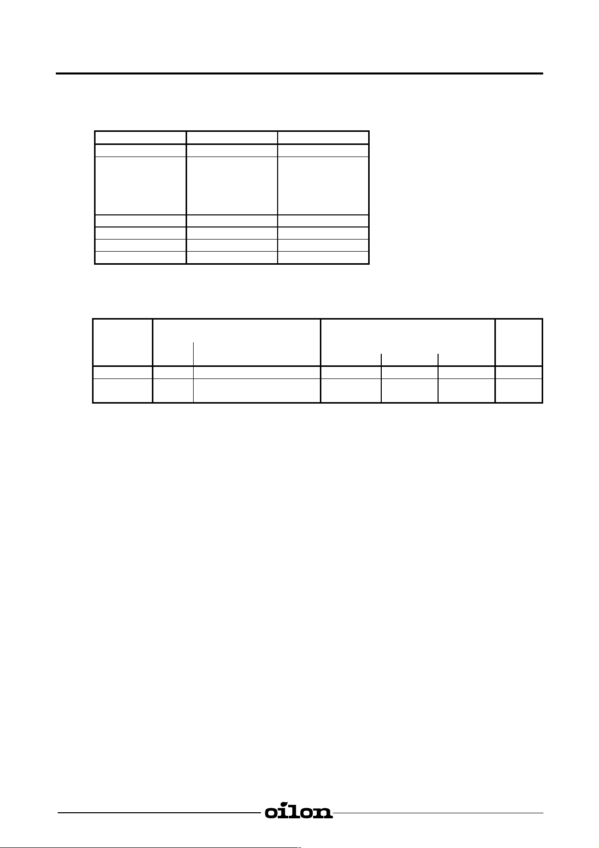
3.1. Technical Data
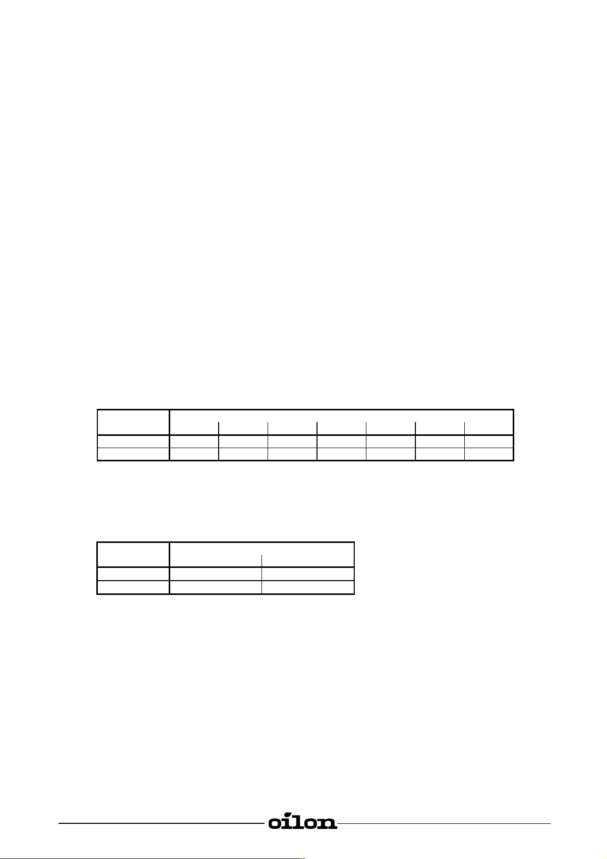
Burner GP-6.10 P GP-6.20 P
Capacity kW 50 - 120 60 - 160
Burner motor
Voltage 50 Hz
Output kW
Current A
Speed rpm
Control unit LFL1.322 LFL1.322
Flame detector Electrode Electrode
Servomotor SQN… SQN…
Weight kg 22 22
Effect of gas inlet pressure on burner capacity range
Burner Gas valve Burner capacity range kW *) Pmax
Conn. Gas inlet pressure pressure
size Type 20 mbar 50 mbar 100 mbar mbar
GP-6.10 P ¾" MB-VEF 407 B01 50 - 120 50 - 120 50 - 120 100
GP-6.20 P ¾"
1 ¼"
1~ 230 V
0,125
1,0
2750
MB-VEF 407 B01
MB-VEF 412 B01
4
1~ 230 V
0,125
1,0
2750
60 - 130
60 - 160
60 - 160
60 - 160
60 - 160
60 - 160
inlet-
100
100
*) The max. capacities given in the table are obtained at a boiler backpressure of 0.
40180036GB
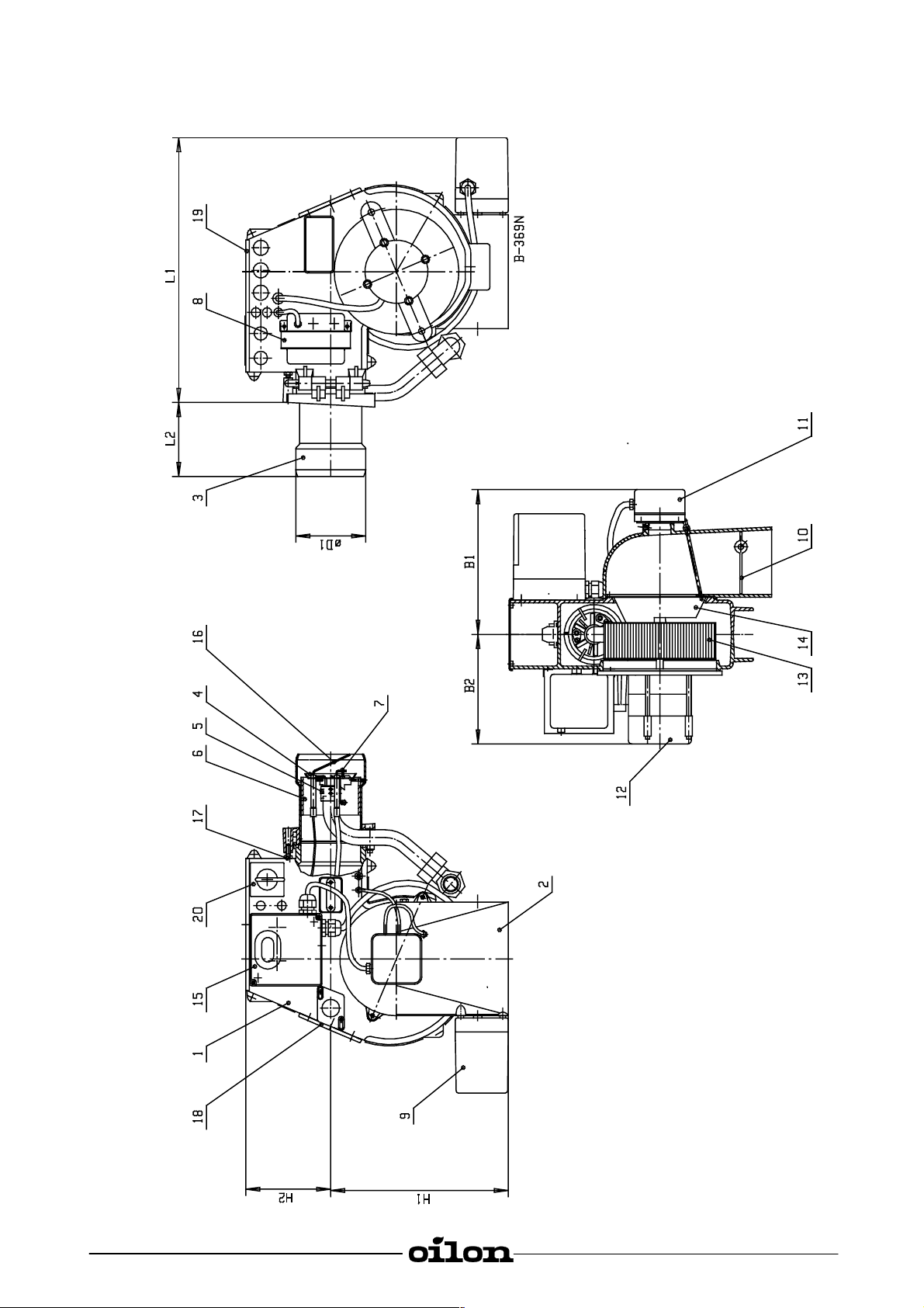
3.2. Basic Assembly Drawing
5
40180036GB
3.3. Parts List
1 Burner housing
2 Air intake
3 Flame tube
4 Diffuser disc
5 Gas nozzle
6 Adjustment ring
7 Ignition electrode
8 Ignition transformer
9 Air damper servomotor
10 Air damper
11 Differential air pressure switch
12 Burner motor
13 Fan wheel
14 Air control cone
15 Control unit
16 Ionization electrode
17 Limit switch (safety switch)
18 Sight glass
19 Protective cover
20 Control switch
6
3.4. Burner Dimensions
Burner Measures in mm
L1 L2 H1 H2 B1 B2
GP-6.10 P 400 110 255 120 210 180 95
GP-6.20 P 400 110 255 120 210 180 100
3.5. Nozzle Table
Burner Nozzle (pcs x hole size)
Natural gas LPG
GP-6.10 P
GP-6.20 P
8 x Æ 4,0 8 x Æ 2,8
8 x Æ 4,0 8 x Æ 2,8
Æ D1
40180036GB
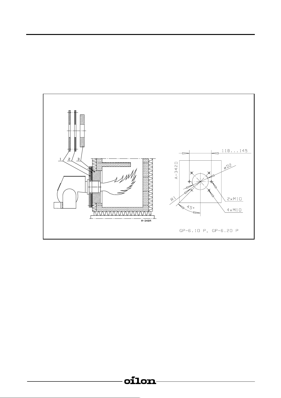
4. Burner Installation
4.1. Burner Mounting
The furnace which has a flame-shaped design does not require refractory. Boilers without
bottom cooling require refractory to prevent heat from reaching boiler foundations.
The flame must at no point come into contact with the furnace walls. If this cannot be avoided,
such points must be covered with refractory. This applies especially to the refractory at the back
wall of short furnaces.
7
1 Mounting plate
2 Gasket plate
3 Thermal insulation
Burner Æ D2 R1
GP-6.10 P 100 70 - 74
GP-6.20 P 105 70 - 74
The mounting plate must have 2 or 4 pcs M10 threaded holes for the mounting of the burner
according to the drawing.
4.2. Hinged Burner Housing
On standard version the burner can be hinged to the left.
4.3. Electric Connections
The burner must be connected according to the electrical diagrams delivered together with the
burner. General and local standards and regulations as well as requirements of electrical
equipment on electrical connections must be adhered to.
40180036GB
8
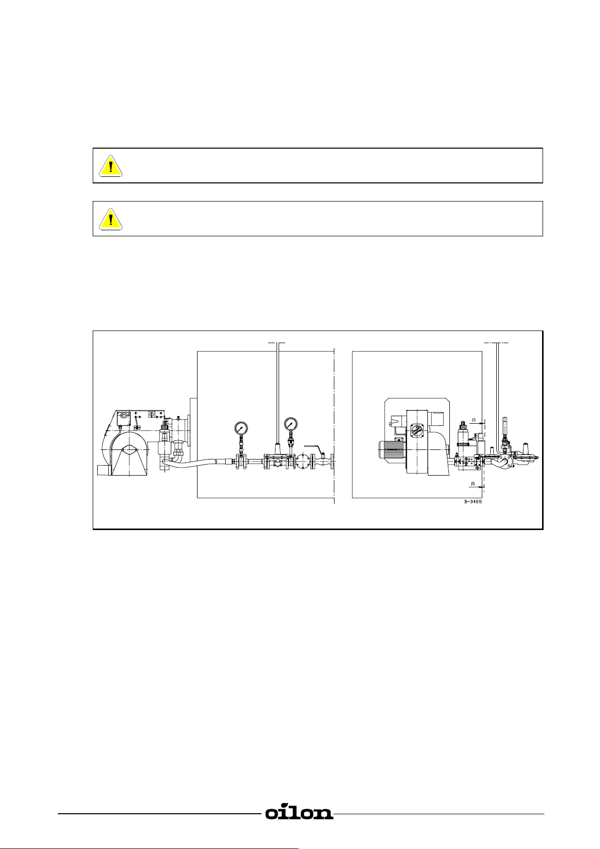
4.4. Example of an Installation of Gas Supply Line
The gas supply line after the pressure regulator must be of the same size or one size larger than
the valve train size.
As standard the gas connection to the burner is from the right side.
Note! A hand-operated shut-off valve must be fitted before the gas valve train.
CAUTION! A separate filter must be fitted before the gas valve train.
CAUTION! The gas valve must be mounted tension free.
Gas pipe venting
A pipe or hose is connected, leading into the open from the measuring connection of inlet
pressure in the gas valve, to discharge the air. For venting open slowly the ball valve in the
supply line and fill the piping with gas. After this close measuring connection.
A - A delivery limit
40180036GB
 Loading...