

Oilon GKP-50 MH, GKP-90 MH Maintenance Manual
M5164 1640EN
13 October 2016
Operation and maintenance manual
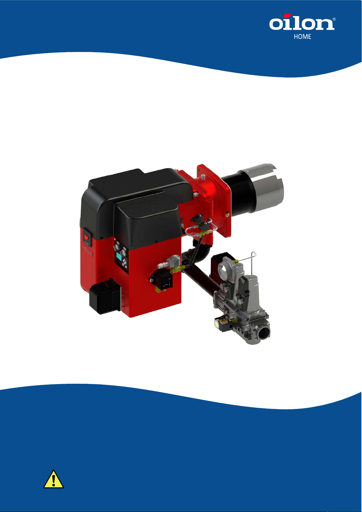
Burner models: GKP-50 MH - 90 MH
Burner equipment: WD34
Read these instructions carefully before installation, use, or maintenance
Original instructions

Contents
1 Introduction
1.1 Liability disclaimer.......................................................................................3
1.2 Safety precautions...................................................................................... 3
1.3 Product overview.........................................................................................6
1.4 Handling and storing...................................................................................8
2 Technical data
2.1 Burner technical data..................................................................................9
2.2 Burner control technical data....................................................................10
2.3 Load controller module technical data......................................................12
2.4 Servomotor technical data........................................................................13
2.5 Control panel technical data..................................................................... 13
2.6 Flame detector technical data.................................................................. 13
2.7 Safety devices, technical data.................................................................. 14
3 Installation
3.1 Space requirements..................................................................................17
3.2 Lifting burner............................................................................................. 17
3.3 Installing burner........................................................................................ 19
3.4 Gas valve selection table......................................................................... 22
3.5 Installing gas module to burner................................................................ 22
3.6 Installing burner to gas supply line...........................................................25
3.7 Installing gas pressure regulating assembly.............................................25
3.8 Installing hoses......................................................................................... 27
3.9 Oil piping................................................................................................... 28
3.10 Electrical connections............................................................................... 30
4 Commissioning
4.1 First start-up.............................................................................................. 32
4.2 Adjusting nozzle and ignition electrodes.................................................. 33
4.3 Oil pump pressure regulation................................................................... 34
4.4 Defining burner capacity...........................................................................34
4.5 Adjusting combustion air...........................................................................35
4.6 Oil pump....................................................................................................36
4.7 Adjusting differential air pressure switch.................................................. 38
4.8 Adjusting gas pressure switch.................................................................. 39
4.9 Setting gas pressure regulator SKP.........................................................40
4.10 Setting gas pressure regulator FRS.........................................................42
4.11 Measuring gas pressure........................................................................... 44
4.12 Operating and display unit........................................................................45
4.13 Display menus.......................................................................................... 46
4.14 Manual start-up and servomotor position checking.................................. 51
4.15 Setting ignition position.............................................................................52
4.16 Setting ignition position, oil (2-stage)....................................................... 53
4.17 Setting ratio curve.....................................................................................54
M5164 1640EN 1 (95)
4.18 Setting ratio curve, oil (2-stage)............................................................... 55
4.19 Capacity range..........................................................................................56
4.20 Capacity range, oil (2-stage).................................................................... 56
4.21 Setting load controller module operating mode........................................ 56
4.22 Setting load controller parameters............................................................57
4.23 Load controller use................................................................................... 60
5 Operation
5.1 Burner operation....................................................................................... 62
5.2 Switch panel..............................................................................................65
5.3 General description of burner operation................................................... 67
5.4 Legend to time sequence diagram symbols and safety times.................. 68
5.5 Time sequence diagram, gas use, without ignition gas............................69
5.6 Operation description, gas use.................................................................69
5.7 Time sequence diagram, oil use, 2-stage................................................ 73
5.8 Operation description, oil use................................................................... 73
6 Maintenance
6.1 Burner maintenance..................................................................................76
6.2 Dismounting combustion head and gas nozzle........................................ 77
6.3 Dismounting and changing burner motor................................................. 79
6.4 Dismounting and changing servomotors.................................................. 80
6.5 Testing safety and control devices...........................................................81
6.6 Resetting fault and reading fault history...................................................87
6.7 Cleaning oil filter....................................................................................... 88
6.8 Troubleshooting.........................................................................................88
6.9 Maintenance during shutdown.................................................................. 92
6.10 Burner parts.............................................................................................. 93
6.11 Burner part list.......................................................................................... 95
2 (95) M5164 1640EN

1 Introduction
1.1 Liability disclaimer
Burner, with the delivered ancillary equipment, is always a part of a larger system.
This manual does not include comprehensive instructions for planning, installing
and operating a complete system. Thus, the designer, installer and operator of the
equipment should have sufficient qualifications and knowledge to design, install,
and operate the parts of the system, as well as the system as a whole. The system,
including burner control system, must be designed and constructed according to local
regulations and requirements.
The following information must be read and understood by the users of the appliance.
The users must be trained and fully qualified according to local legislation for the
specific work. The users of the appliances must also be capable to recognize possible
hazards in the system and in the environment where the appliance is used.
This manual contains information and instructions based on product standards and
regulations, and on our best knowledge. Failure to follow these instructions can lead
to damage to the appliance. Erroneous use of the appliance or the failure to follow any
instructions or warnings in the manual or this disclaimer can lead to property damage,
personal injury or death.
Oilon is unable to accept any liability for damage in case of:
● failure to follow these instructions
● other use than what is explained in this manual
● use by unqualified personnel
● the use of spare parts not provided by Oilon.
Your legal rights are governed by a Limited warranty, the terms of which are
incorporated herein by reference. Any modification at the product, if not approved by
Oilon, is disclaimed and may void your rights under the Limited warranty.
1.2 Safety precautions
Read these instructions carefully before installation, commissioning, operation or
maintenance of the device. The given instructions must be followed. Throughout this
manual, the following three symbols are used to point out very important information:
Be careful. The DANGER symbol indicates a possible danger of bodily
harm or lethal injury.
Pay attention. The CAUTION sign indicates a possible danger of
damage to the device, components or surroundings.
M5164 1640EN 3 (95)

Note indicates tips, hints, and other essential information.
Keep these instructions as well as the electrical diagrams available near the
device.
Oilon products are manufactured according to general product standards and
directives, and based on our best knowledge about product design, and technologies.
Operation safety is one of the leading principles in our product development. However,
it is wise to be prepared, and think about safety. Read the following principal safety
warnings and instructions:
Installation, commissioning, or service of the appliance is to be carried
out by authorized and trained personnel only, adhering to all local
regulations and requirements.
The equipment shall be installed in accordance with the Provincial Installation
Requirements, or in their absence, the CGA B149.1 and B149.2 Installation Codes
shall prevail.
IN CASE OF FIRE OR OTHER EMERGENCY
● Cut off power supply.
● Close main fuel shut-off valve.
● Take appropriate actions.
● Contact operation controller.
IN CASE OF A GAS LEAKAGE
● Do not light fire or touch electric equipment.
● Close main fuel shut-off valve.
● Make sure there are no people in the leakage area.
● Make sure the leakage area is properly ventilated.
● Contact operation controller.
Cut off power supply to burner and close manual shut-off valves always
before any maintenance work. Cutting power is adequate when just
inspecting the device.
Connectors in control box are under voltage. Only authorized users may
open safety cover.
Fasten all safety covers, enclosures, and guards with all screws before
start-up. Use appropriate tools.
Wear proper hearing protection and personal protective equipment,
such as protection shoes and gloves when necessary.
4 (95) M5164 1640EN
Do not use Teflon tape in piping.
If burner start-up fails consecutively two times, do not restart burner
before carefully investigating the reason for the failure.
Do not touch hot pipes or surfaces during operation or maintenance.
Emergency shutdown
In an emergency, cut off power supply to the burner. Close the manual shut-off
valves. After safety check you can restart the burner. Check settings, and monitor that
operation continues as normal.
Take care of the boiler room
Never use open fire while checking burner or boiler.
Do not store any inflammable materials in boiler room.
Keep boiler door closed while starting burner, and during burner
operation.
● Maintain tidiness in boiler room, and keep boiler room door closed.
● Make sure that there is always enough water and pressure in heating system.
● Make sure boiler and chimney are swept regularly.
● Check flue damper adjustment and gate valve regularly.
● Make sure burner room air-inlet gap is open.
● Make sure shut-off valves on pressure gauges are shut.
● Make sure pipeworks tightness, boiler system safety appliances, pipeworks, and
burner are checked regularly according to the rules and regulations of public
authorities.
● Check boiler and its components.
We recommend a maintenance contract.
WARNING
IF YOU SMELL GAS, OPEN WINDOW, EXTINGUISH ANY OPEN FLAMES,
STAY AWAY FROM ELECTRICAL SWITCHES, EVACUATE THE BUILDING AND
IMMEDIATELY CALL THE GAS COMPANY.
IN ACCORDANCE WITH OSHA STANDARDS, ALL EQUIPMENT, MACHINES AND
PROCESSES SHALL BE LOCKED OUT PRIOR TO SERVICING.
M5164 1640EN 5 (95)

IF THIS EQUIPMENT IS NOT INSTALLED, OPERATED AND MAINTAINED IN
ACCORDANCE WITH THE MANUFACTURERS INSTRUCTIONS, THIS PRODUCT
COULD EXPOSE YOU TO SUBSTANCES IN FUEL OR FROM FUEL COMBUSTION
WHICH CAN CAUSE DEATH OR SERIOUS ILLNESS AND WHICH ARE KNOWN TO
CAUSE CANCER, BIRTH DEFECTS OR OTHER REPRODUCTIVE HARM.
IMPROPER SERVICING OF THIS EQUIPMENT MAY CREATE A POTENTIAL
HAZARD TO EQUIPMENT AND OPERATORS.
SERVICING MUST BE DONE BY A FULLY TRAINED AND QUALIFIED PERSONNEL.
WARNING
DO NOT ATTEMPT TO START, ADJUST OR MAINTAIN THIS BURNER WITHOUT
PROPER TRAINING OR EXPERIENCE. FAILURE TO USE KNOWLEDGEABLE
TECHNICIANS CAN RESULT IN EQUIPMENT DAMAGE, PERSONAL INJURY OR
DEATH.
1.3 Product overview
Intended use
This is an automatic forced draught burner. The burner can be used on most heating
appliances; for warm and hot water boilers, hot air generators, and various types of
process heating. They are also designed to suit furnaces with high back pressure.
The burners can be mounted in horizontal, vertical and upward facing, or vertical and
downward facing orientation. Our burners are designed for operation in covered areas,
within the temperature range of 0 °C – +50 °C / + 32 °F – 105 °F. The standard setup is
designed to operate in the altitude of max. 500 m / 1,640 ft above sea level.
See Technical data for the information on standard applicable fuels. Burners using
other fuels are available upon request.
Construction
The surface of the housing is finished with durable high-gloss paint. Electrical
installations and burner service are easy to perform because the top cover is
removable. The stainless steel alloy combustion head and the diffuser disc can
withstand high temperatures.
The burner control system handles all burner operation sequences automatically. In the
event of a burner failure, the unit stops the burner automatically.
Each burner is tested separately before delivery to the customer.
For more information on products, visit our web site at www.oilon.com: Oilon –>
Industries –> Product material.
Information on components can be found under the headline Burner parts.
6 (95) M5164 1640EN
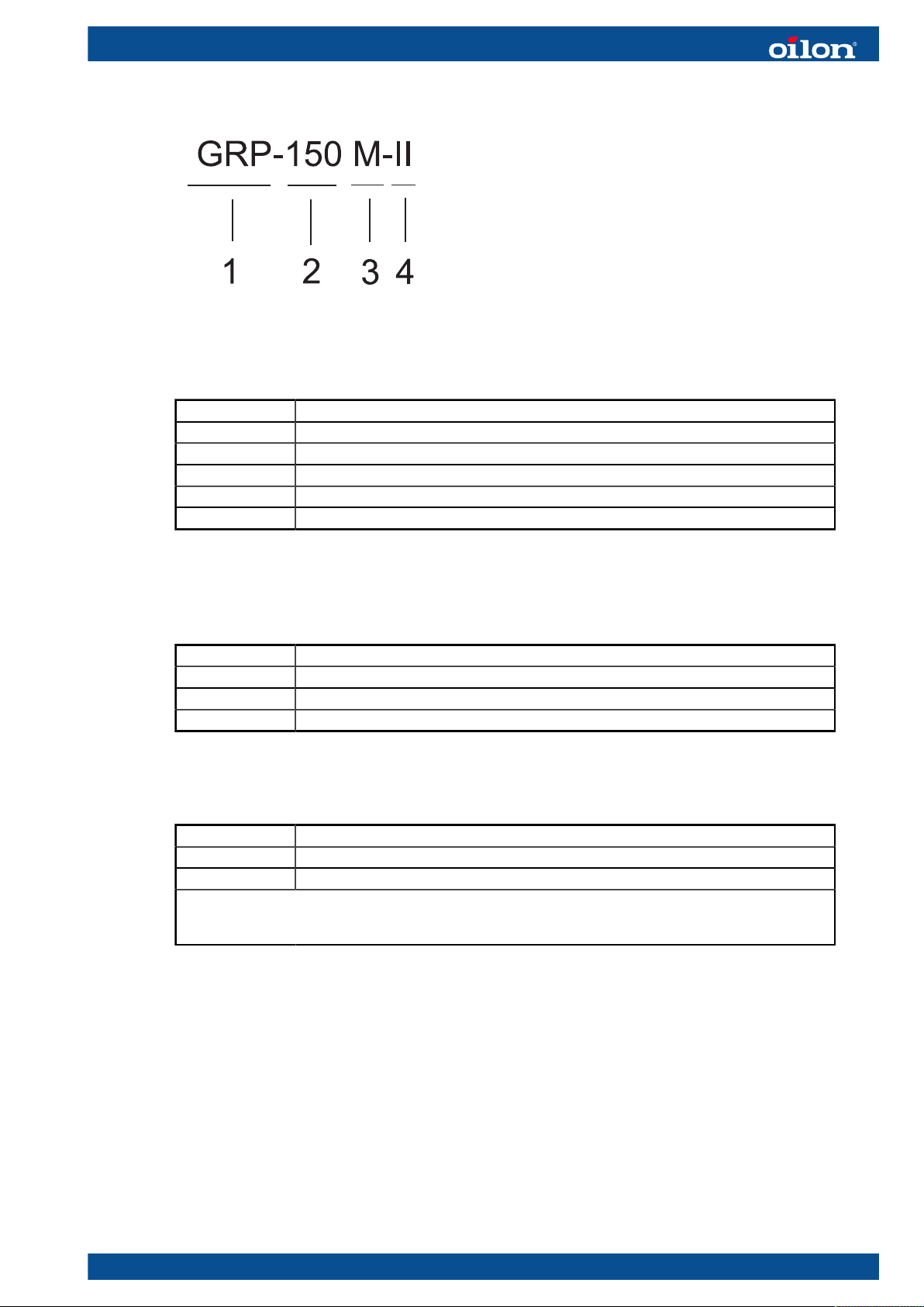
Type labelling
POLTINKOODI ver. 2
Label element 1: Fuel
KP Light fuel oil
RP Heavy fuel oil
GP Gas
GGP Dual gas
GKP Gas, light fuel oil
GRP Gas, heavy fuel oil
Label element 2: Burner size categorization
Label element 3: Method of control
H Two-stage
M Modulating
MH Modulating gas, two-stage oil
ME Modulating with a separate fan
Label element 4: Additional code, for example burner capacity I-III or automation, like
WD34
WD32 BT 320 burner control (one fuel, non-permanent operation)
WD33 BT 330 burner control (one fuel, permanent operation)
WD34 BT 340 burner control (two fuels, permanent operation)
- capacity controller LCM100 as an option to LSB bus (WD32, WD33)
- capacity controller LCM100 and dual-fuel burner module DFM300 are mandatory to LSB bus with
WD34, when using a dual-fuel burner
Type plate
The following illustration shows an example of the type plate of Oilon burners:
M5164 1640EN 7 (95)

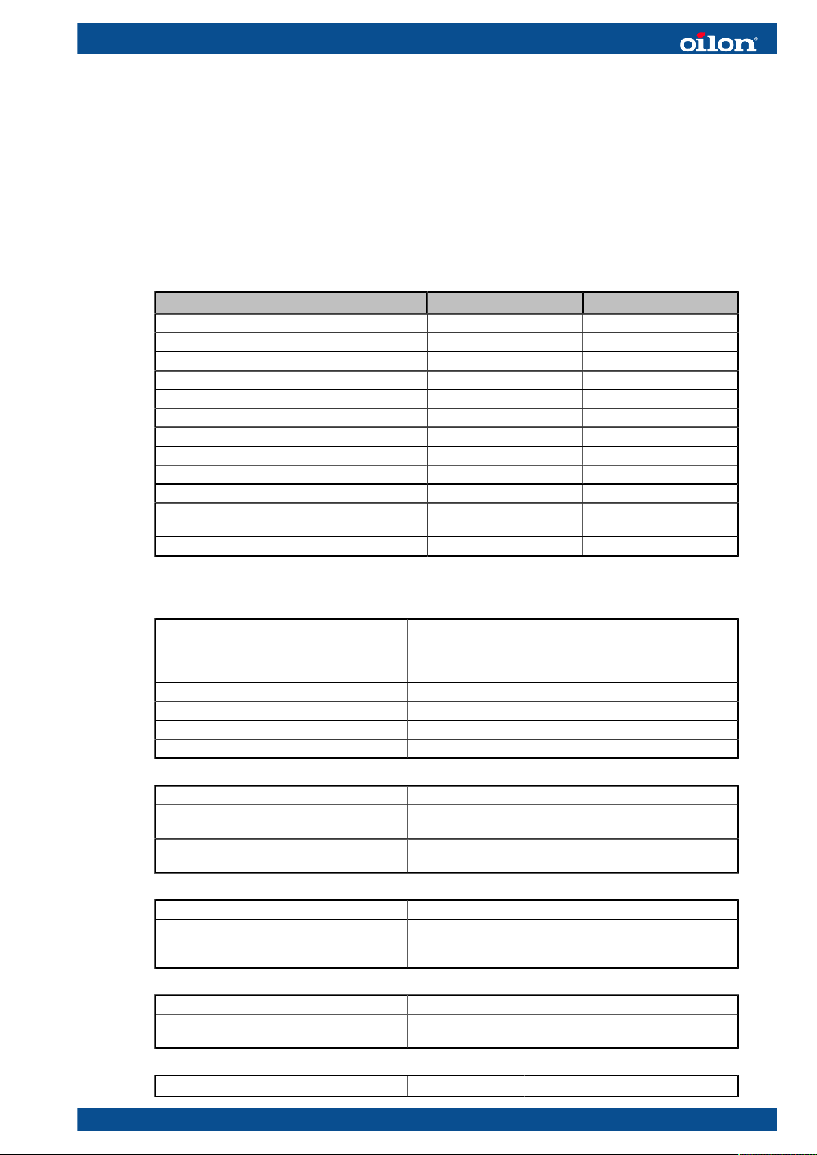
Type plate US ver. 1
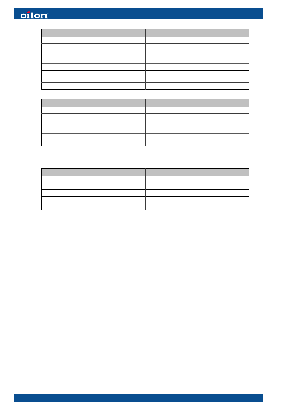
Pos. Description Pos. Description
1 Burner type:
KP = Light fuel oil
RP = Heavy fuel oil
GP = Gas
GKP = Light fuel oil and gas
GRP = Heavy fuel oil and gas
2 Overfire pressure min, IN.WC 10 Serial number
3 Overfire pressure max, IN.WC 11 Month and year of manufacture
4 Gas calorific value, BTU/scf 12 Capacity, gas, MBTU/hr
5 Gas type 13 Capacity, light fuel oil, GPH
6 Oil quality / viscosity 14 Gas pressure min, IN.WC
7 Supply voltage, input power and current,
V / Hz / A / kW
8 Manufacturer address 16 L LC US marking and certification
9 Degree of protection
15 Gas pressure max, IN.WC
institute code
1.4 Handling and storing
Storing and recycling
Store device and its equipment in a dry and airy place. Protect device from dust and
humidity. Follow storing and transporting instructions included in the package.
Documentation is part of the product, and it must be passed on together with device,
also with a second hand product. Pass on documents delivered with device to owner
at installation, and advise to keep them properly. Make sure that operating instructions
are available near the device.
Recycle product package. The metal and plastic parts of the device are made of
recyclable materials. Also all electrical components are recyclable, and should be
handled according to local regulations.
8 (95) M5164 1640EN
2 Technical data
2.1 Burner technical data
Burner data
Burner GKP-50 MH GKP-90 MH
Capacity kW, gas 100–800 250–1460
Capacity MBtu, gas 341–2,730 853–4,981
Capacity kg/h, oil 17–68 30–130
Capacity lb/h, oil 37.5–149.9 66.1–286.6
Max. turndown ratio, gas use 1:8 (100–12.5%) 1:6 (100–16.5%)
Max. turndown ratio, oil use 1:2 (100–50%) 1:2 (100–50%)
Nominal motor output, kW 0.75 2.2
Nominal motor output, hp 1.00 2.95
Oil inlet pressure to pump, bar 0.5–2 0.5–2
Oil inlet pressure to pump, PSI 7.25–29 7.25–29
Oil operating pressure (atomizing pressure), kPa
(bar)
Oil operating pressure (atomizing pressure) PSI 145–290 145–290
1000–2000 (10–20) 1000–2000 (10–20)
Other technical data and requirements
Fuel, gas use Natural gas
When using other gases than natural gas, the composition
of the gas must be known. Consult burner manufacturer on
the suitability of the burner for special gases.
Gas inlet pressure to burner max. 500 mbar
Gas inlet pressure to burner max. 7.25 PSI
Max. demand for combustion air, gas use 13 m³ / 10 kW
Max. demand for combustion air, gas use 459.09 ft³ / 13.5 MBtu
Fuel, oil use #2 fuel oil
Efficiency, #2 fuel oil 2.20 lb ≈ 40.46 MBtu efficiency, when heat value is 1146.03
Btu/ft³
Max. demand for combustion air, oil use 15 m³/kg
529.72 cfh/lb
Control voltage 120 V (-15%...+10%) 50 Hz / 60 Hz 1-phase
Motor voltage options 220 V 60 Hz 3-phase
460 V 60 Hz 3-phase
575 V 60 Hz 3-phase
Degree of protection NEMA 1
Ambient temperature range 0...+ 50 °C
32...+ 122 °F
L
Noise level
= 77.5 ± 0.5 dB
pfA
M5164 1640EN 9 (95)
For reducing noise level, contact the manufacturer.
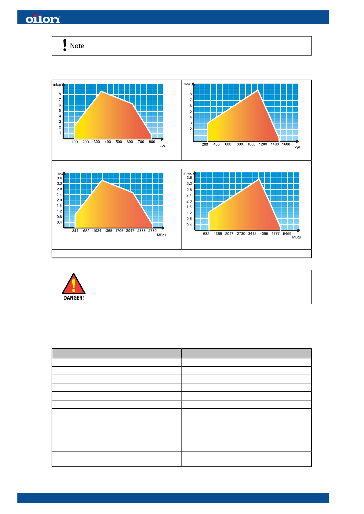
Working diagrams
GKP-50 MH
1 kg/h = 11.86 kW
GKP-50 MH
2.20 lb ≈ 40.46 MBtu
Usage of burner outside the heat input and pressure curves is
forbidden.
GKP-90 MH
GKP-90 MH
2.2 Burner control technical data
Burner control BT 300 series
Power supply 115 VAC –15/+10 %
Locking from undervoltage Less than 85 % of nominal
Mains frequency 50 Hz / 60 Hz
Power consumption < 30 VA
Internal shielding Safety equipment, do not self-service.
External fuse max. 10 A slow
Input signals Capacitance should be below 2.2mF.
Output signals 3 fuel valves max. 1 A cos 0.4
fan max. 2 A cos 0.4
oil pump max. 2 A cos 0.4
ignition transformer
alarm output
Permissible ambient temperature -20...+60 °C
-4...+140 °F
10 (95) M5164 1640EN
Main standards
● ANSI/UL 372
● ANSI/UL 60730-1
● ANSI/UL 60730-2-5
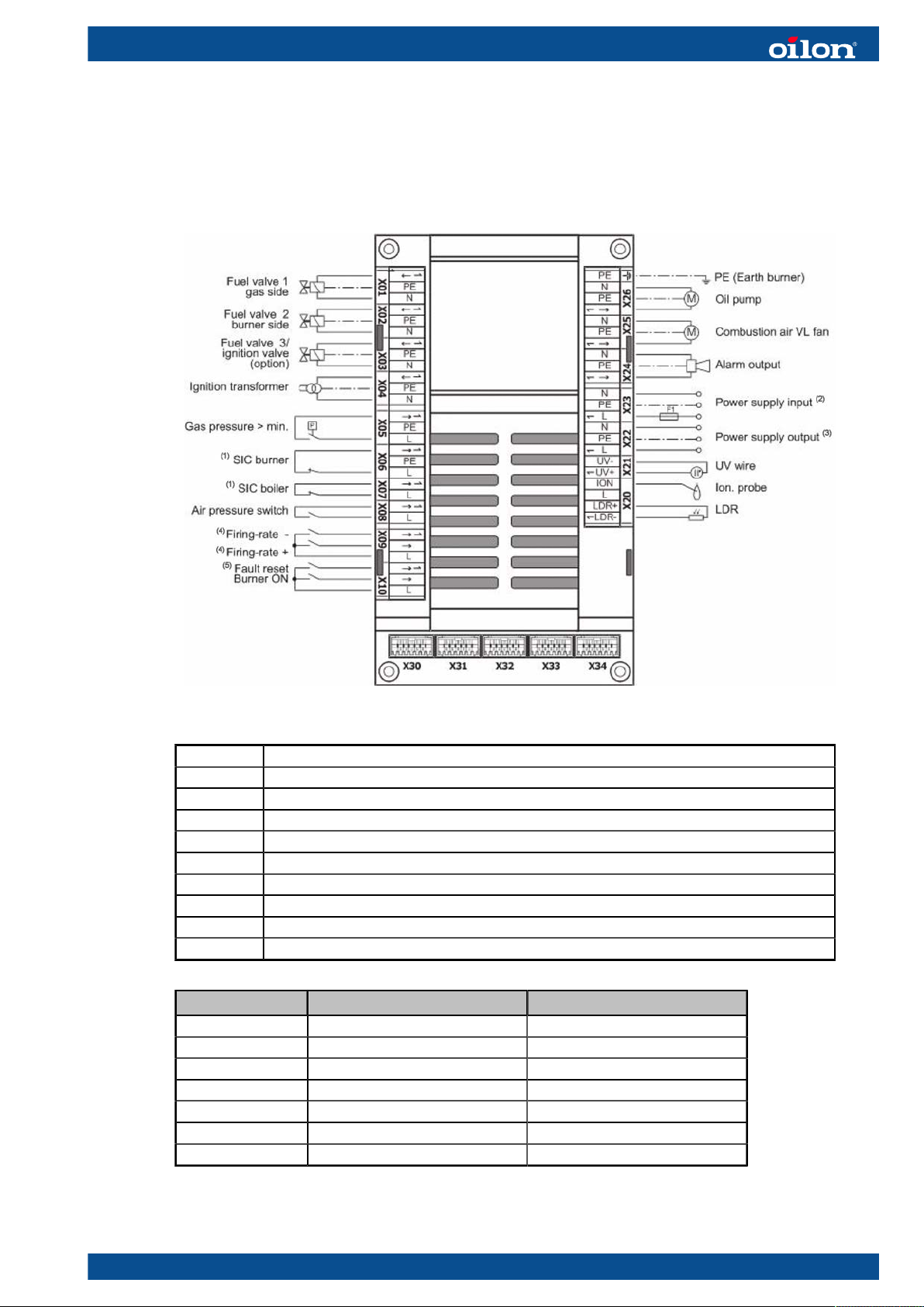
Burner control BT 300 connector interface
BT300 connector interface ver. 3
X30 user interface UI 300
X31 LSB optional (LCM)
X32 continuous output 1, air damper
X33 continuous output 2, gas damper
X34 continuous output 3, oil damper
(1) SIC = safety interlock chain
(2) 115 VAC 47–63Hz external fuse protection required (max 10A slow-blow)
(3) 115 VAC for power supply to external devices
(4) Fuel selection for dual-fuel burners with BT340 + DFM300
(5) Alternative CPI/POC connection
Cable Maximum cable length, m Maximum cable length, ft
X01–X10 10 32
X20–X21 3 9
X22–X23 unlimited unlimited
X24–26 10 32
X30 1 3
X31 1 3
X32–X34 3 9
M5164 1640EN 11 (95)
2.3 Load controller module technical data
Safety equipment, do not self-service.
Load controller module LCM100
Power supply 90–250 VAC
Mains frequency 50–60 Hz 6 %
Power consumption 18.2 VA
Permissible ambient temperature -20...+60 °C
-4...+140 °F
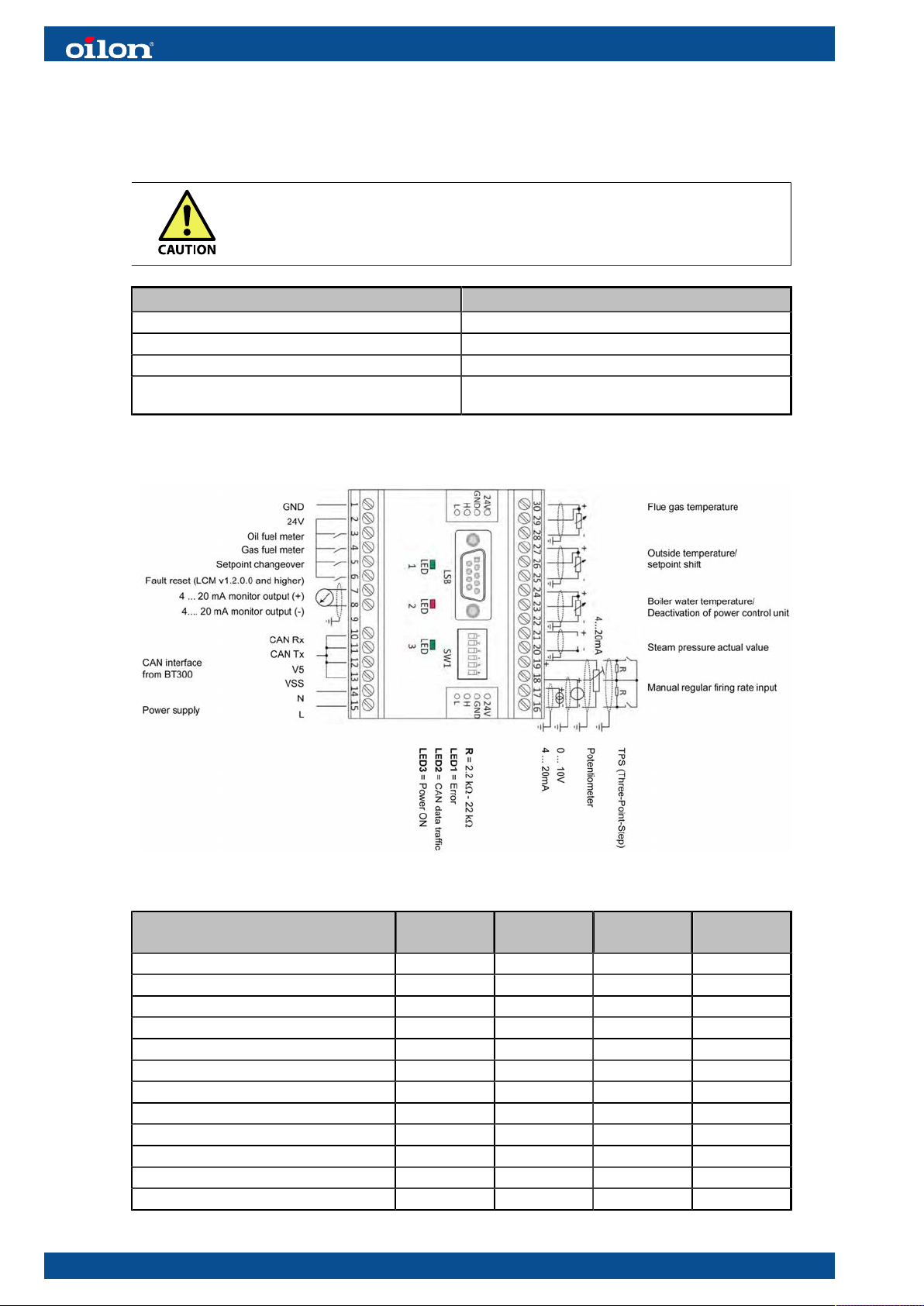
LCM connector interface
LCM connector interface ver. 3
Cable assembly Type Shield Cable
length, m
Network input AC in - 100 328
24 V external DC out - 100 328
LSB IO - 1 3
CAN IO X 100 328
Fuel measurement oil I - 10 32
Fuel measurement gas I - 10 32
Setpoint changeover I - 10 32
Extra input I - 10 32
Flue gas temperature I X 100 328
Ambient temperature I X 100 328
Boiler water temperature I X 10 32
Steam pressure I X 10 32
Cable
length, ft
12 (95) M5164 1640EN
Cable assembly Type Shield Cable
length, m
Combination input 20 mA I X 100 328
Combination input term. 18 I X 100 328
Analog output mA O X 100 328
Cable
length, ft
I = Input
O = Output
Shielded cable must always be connected to TE terminal.
2.4 Servomotor technical data
Servomotor 662R5001 662R5003 662R5010
Interface LSB (Lamtec system bus) LSB (Lamtec system bus) LSB (Lamtec system bus)
Turning angle 90° 90° 90°
Accuracy ±0.2° ±0.2° ±0.2°
Torque, operation/hold 1.2/0.8 Nm
10.62/7.08 lb-in
Running time/90 degrees 5 s 5 s 15 s
Protection degree NEMA 12 NEMA 12 NEMA 12
Permissible ambient
temperature
-20...+60 °C
-4..+140 °F
3/2.8 Nm
26.55/24.78 lb-in
-20...+60 °C
-4..+140 °F
9/6 Nm
79.65/53.10 lb-in
-20...+60 °C
-4..+140 °F
2.5 Control panel technical data
Control panel UI 300
Interface LSB bus
Display 128 x 64 pixel, backlighting
Protection degree NEMA 1
Permissible ambient temperature -20...+60 °C
-4...+140 °F
2.6 Flame detector technical data
M5164 1640EN 13 (95)
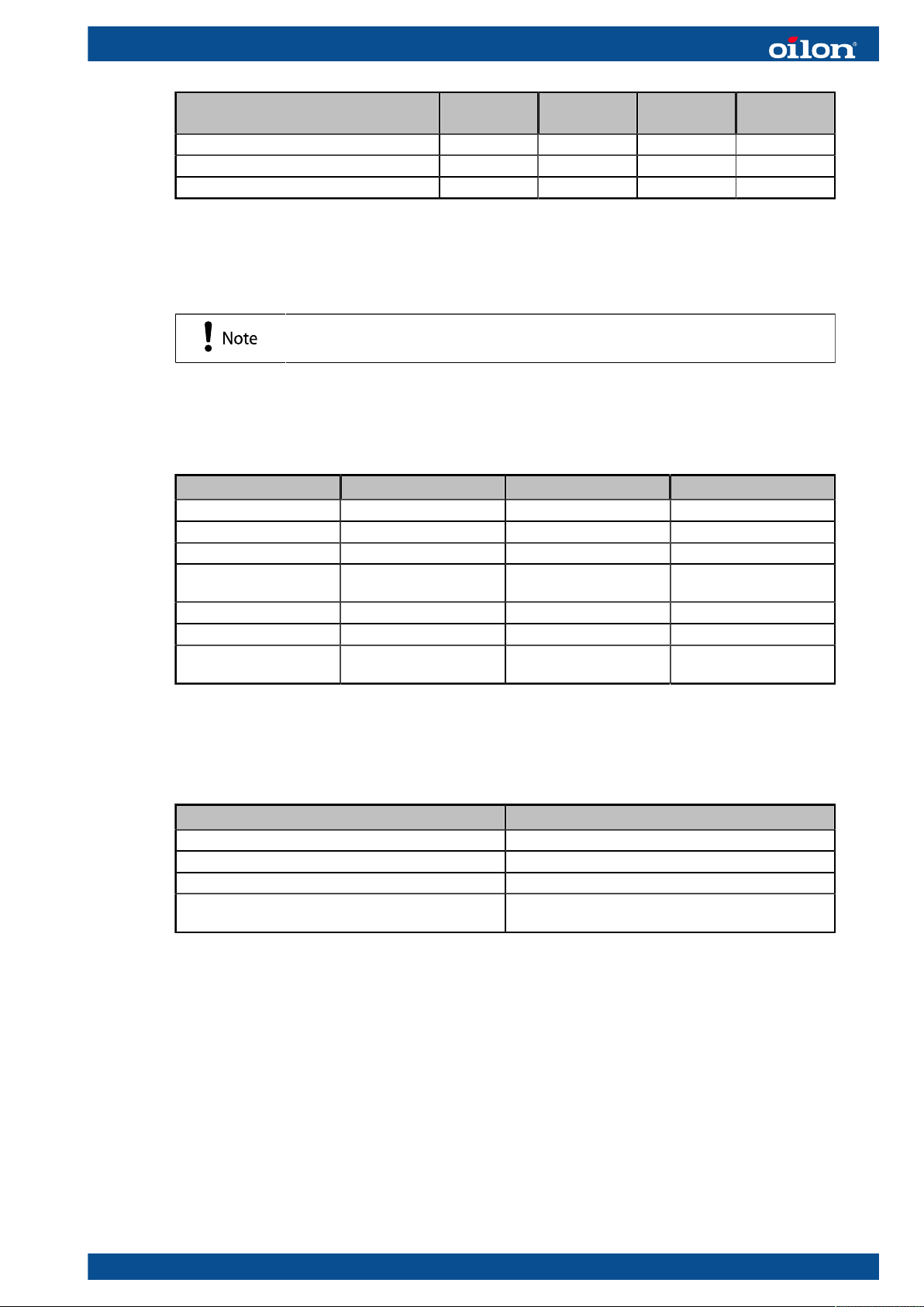
QRA
UV-cell connection ver. 2
Measuring range 0–100%
Supply voltage 115 VAC –15/+10 %
Min. required detector current * 35 µA
Max. possible detector current * 50 µA
* When supply voltage 230 V
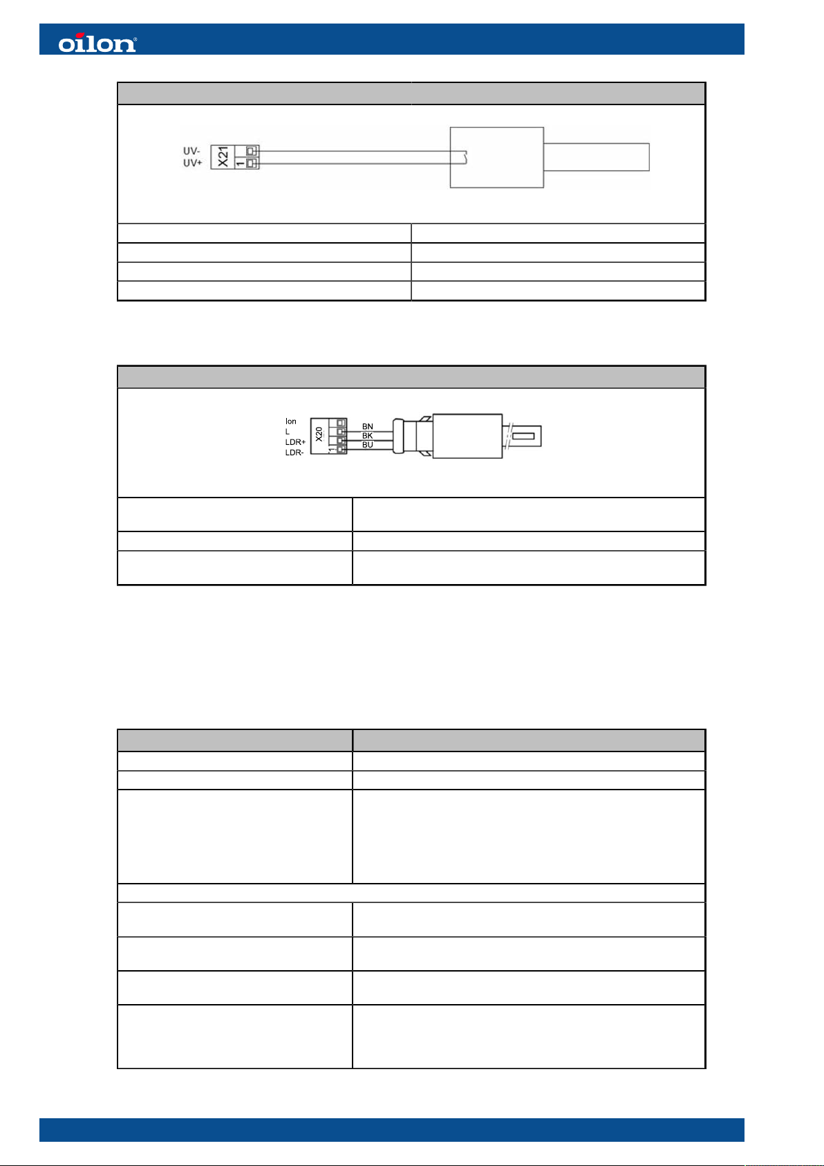
KLC
KLC connection ver. 1
Supply voltage 120 VAC -15/+10%
Frequency 50 – 60 Hz
Output (FET) Switch-on delay 0,5 s. Acceptable loss of flame ca. 0,2 s
Operating Temperature -4 ºF to +140 °F (temperatures >120 °F reduces the lifetime of
the UV-tube)
2.7 Safety devices, technical data
Gas pressure switch
Type Dungs GMH/GML/GAO A4-4-…
Maximum operating pressure 7 PSI (500 mbar)
Adjustment range See cover of switch
Hysteresis
GAO-A4-4-2
GAO-A4-4-3
GAO-A4-4-5
GAO-A4-4-6
GAO-A4-4-8
Temperature range:
- GAO-, GMH- and GML-A4-4 Ambient temperature -40 °F to +140 °F (-40 °C to +60 °C)
- GAO-, GMH- and GML-A4-4-8 Ambient temperature -22 °F to +140 °F (-30 °C to +60 °C)
Switching voltage AC eff. min. 24 V max. 240 V
Switching current AC 10 A resistive @ 120 VAC
in. W.C.
≤ 0.12
≤ 0.20
≤ 0.40
≤ 1.2
≤ 4.0
Medium temperature -40 °F to +140 °F (-40 °C to +60 °C)
Medium temperature -22 °F to +140 °F (-30 °C to +60 °C)
DC min. 24 V max. 48 V
AC 8 A inductive @ 120 VAC
DC min. 20 mA @ 24 VDC
DC max. 1 A @ 24 VDC & 48 VDC
14 (95) M5164 1640EN
Type Dungs GMH/GML/GAO A4-4-…
Degree of protection NEMA 4
Installation position Switch orientation has an effect on setting value. Standard
orientation: sensing port horizontal. For other positions, refer to
switch manufacturer’s documentation.
Component standard UL Listed
● UL 353
● File # MH 16628
CSA Certified
● CSA C22.2 No. LR 53222
● Certification file # 201527
FM Approved
● Class 3510, 3530
● File # J.I. 1Y919.AF
Differential pressure switch
Type Type Dungs AA-A2-4-5
Maximum operating pressure 7 PSI (500 mbar)
Adjustment range 2.00-20.00 in. W.C (5–50 mbar)
Hysteresis ≤ 0.40 in. W.C (1 mbar)
Allowed ambient and medium temperature -40 °F to +140 °F (-40 °C to +60 °C)
Switching voltage AC 24–250V
DC 24–48V
Switching current AC 5A resistive @ 120 VAC
AC 3A inductive @ 120 VAC
DC min. 20 mA @ 24 VDC
DC max. 1A @ 12–48 VDC
Degree of protection NEMA 12
Installation position Multi-positioned
Component standard UL Listed
● UL 353
● File # MH 16628
CSA Certified
● CSA C22.2 No. 14
● File # 201527
FM Approved
● Class 3510, 3530
● File # J.I. 0D6A1.AF
SKP gas pressure regulator, gas valve actuator + VGD gas valve
Type Siemens SKP25…
Operating voltage 110–120 VAC –15/+10 %
Adjustment range 0.2–100.37
Allowed ambient and medium temperature -50 °F ... +140 °F
Degree of protection NEMA 12
Closing time <0.8 s
Opening time 3–6 s, depending on valve size
Installation position Other positions possible except vertically upside
down
Component standard UL/429, FM/7400, ANSI Z21.21/CSA 6.5 C/I
ANSI Z21.18/CSA 6.3
M5164 1640EN 15 (95)
Type Siemens SKP15…
Adjustment range 110–120 VAC –15/+10 %
Allowed ambient and medium temperature -50 °F ... +140 °F
Degree of protection NEMA 12
Closing time <0.8 s
Opening time 3–6 s, depending on valve size
Installation position Other positions possible except vertically upside
down
Component standard UL/429, FM/7400, ANSI Z21.21/CSA 6.5 C/I
Type Siemens VGD 20/40
Maximum operating pressure 240.88 in.W.C
Allowed ambient and medium temperature 5 °F ... +140 °F
Group, according to EN 161 2
Installation position Pressure regulator determines position
Component standard UL/429, FM/7400
CSA/ANSI Z21.21/CGA 6.5 Commercial/Industrial
Oil valve
Type ASCO 8262H011V
Maximum operating pressure 350 PSI
Capacity 9.1 W
Allowed ambient temperature 5–131 °F
Allowed medium temperature 210 °F
Component standard UL429
16 (95) M5164 1640EN
3 Installation
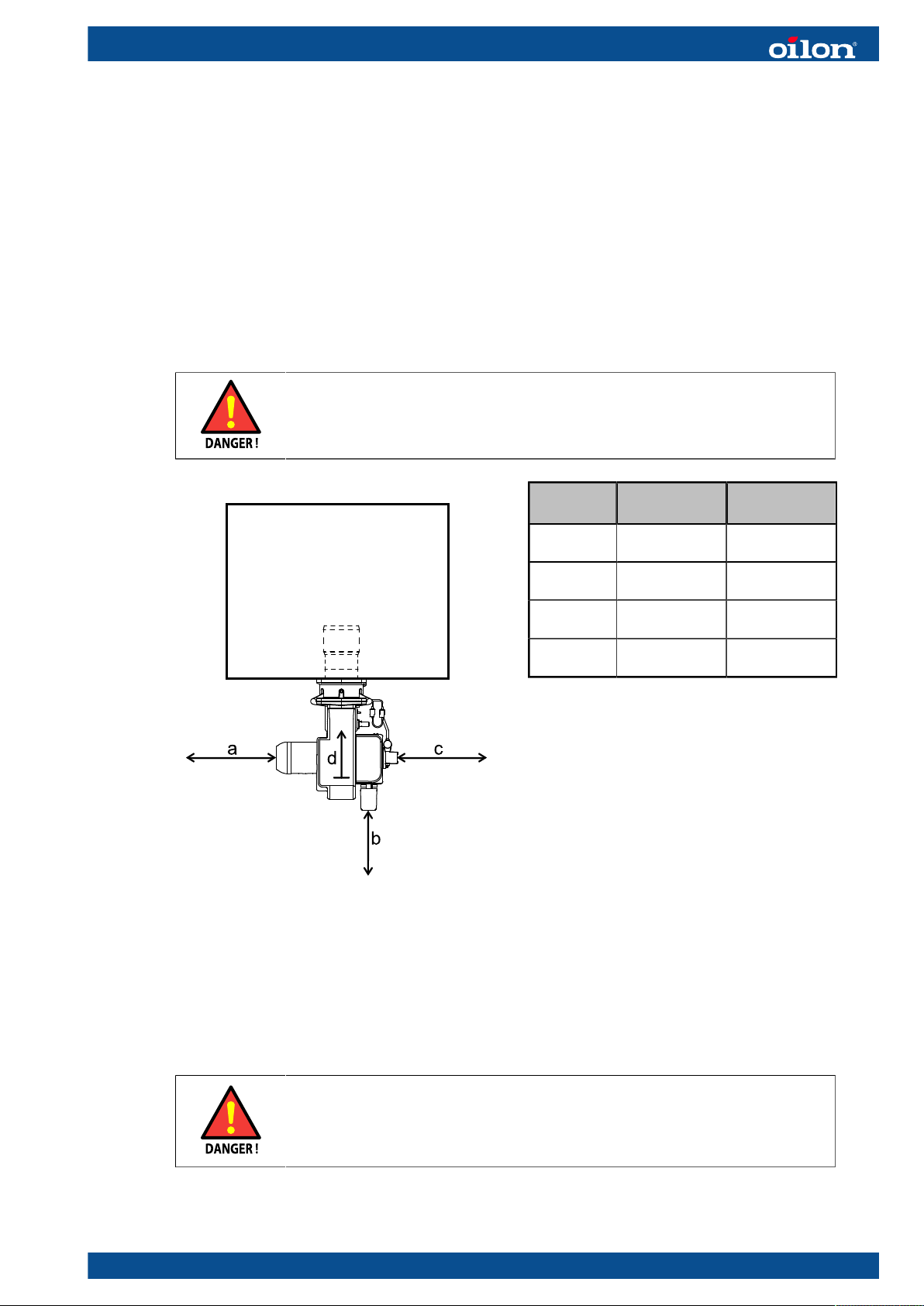
3.1 Space requirements
Leave enough space on each side of the burner for installation, commissioning,
and maintenance purposes. The minimum space requirements are presented in the
following.
Installation, commissioning, or service of the appliance is to be carried
out by authorized and trained personnel only, adhering to all local
regulations and requirements.
Space requirements ver. 1
Legend
a
(left)
b
(front)
c
(right)
d
(top)
Minimum
dimension, cm
80 2.6
80 2.6
80 2.6
100 3.3
Minimum
dimension, ft
It is recommended to leave more space around the burner. These are only the
minimum requirements.
3.2 Lifting burner
● Lifting the device can only be performed by a qualified person, who
knows the regulations and safety instructions for lifting.
● Always use all lifting points of the lifting direction.
● Do not go under a supported device.
M5164 1640EN 17 (95)
The burners are attached and supported to a transportation base. The base can be
lifted from all sides with a forklift. When lifting the package, the center of gravity must
be in the middle between the forks to avoid falling.
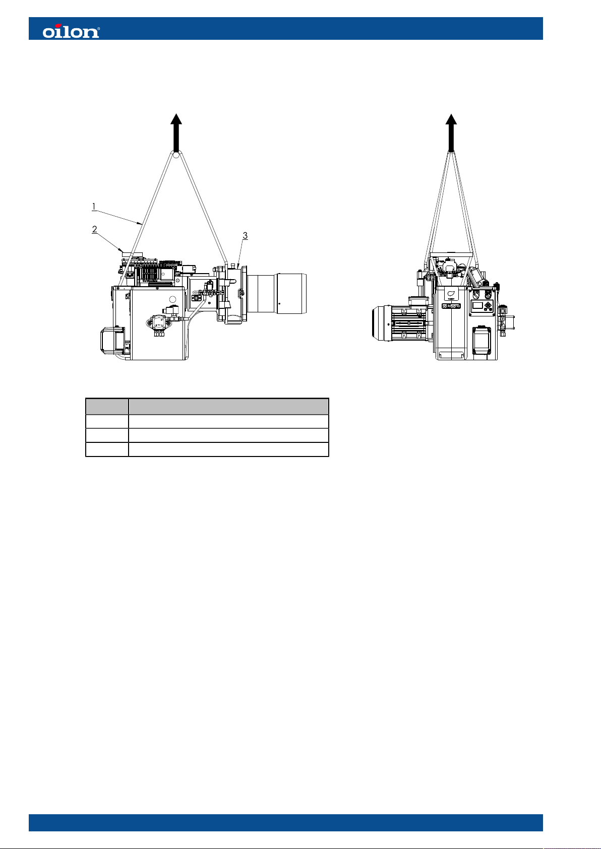
Lifting D047033 ver. 2
Pos. Item
1 Lifting belt
2 Lifting support
3 Gas frame
To lift the burner:
1. Remove the burner cover.
2. Set the lifting belt (1) around the flame sight tube and the gas frame (3).
3. Place the lifting support (2) between belts according to the drawing. Make sure, that
the lifting devices do not touch electrical devices.
4. Lift the burner as shown in the illustration.
5. After lifting, remove the lifting devices and fasten the cover on its place.
18 (95) M5164 1640EN
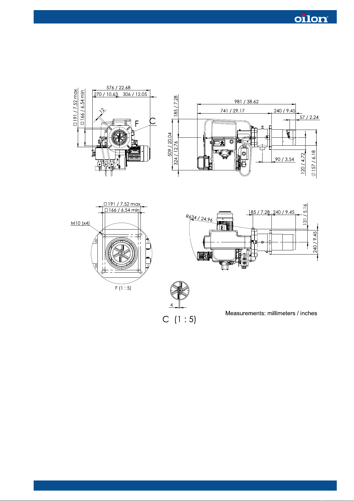
3.3 Installing burner
GKP-50 MH main dimensions
D048897 ver. 3
M5164 1640EN 19 (95)

GKP-90 MH main dimensions
D048844 ver. 3
Mounting dimensions
A-349A ver. 2
1 Mounting plate
2 Insulating plate
3 Ceramic wool or similar
L (mm)
Burner
240 / 300
300 / 400
L (inch)
20 (95) M5164 1640EN
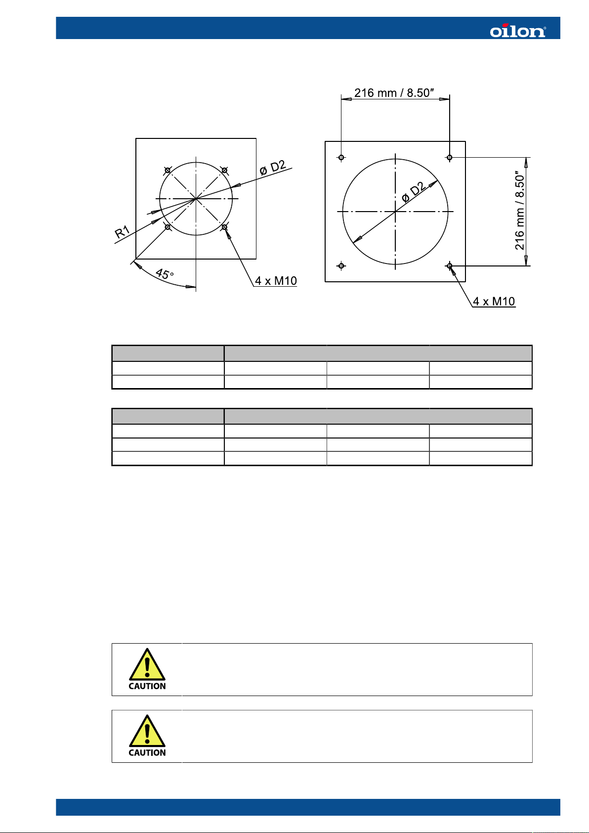
50 H / M / MH 90 H / M / MH
Burner
ø D2 R1 L
50 H / M / MH 165 117.5-135 240 / 300
Burner
ø D2 R1 L
50 H / M / MH 6.50 4.63–5.31 9.45 / 11.81
90 H / M / MH 8.27 11.81 / 15.75
Mounting dimensions, mm
Mounting dimensions, inches
To mount the burner:
1. Prepare the boiler front plate according to the given dimensions.
2. Coat the bolt threads with graphite-bearing grease prior to fitting.
3. Install the burner so that the motor shaft lies horizontally.
4. Remove the transportation bracket after the burner is attached to the boiler.
5. Make sure there is enough free space on the side to allow the burner to swing fully
open.
As standard, the burner swings to the left. The GKP-90 MH model can also be hinged
to the right side.
Install burner firmly. Vibration may damage burner or its components.
Switch off electric power from the burner before burner swing-out.
M5164 1640EN 21 (95)
Do not install the burner upside down. Make sure the burner is firmly
attached.
3.4 Gas valve selection table
The max. capacities shown in the table are achieved when the boiler
back pressure is 0.
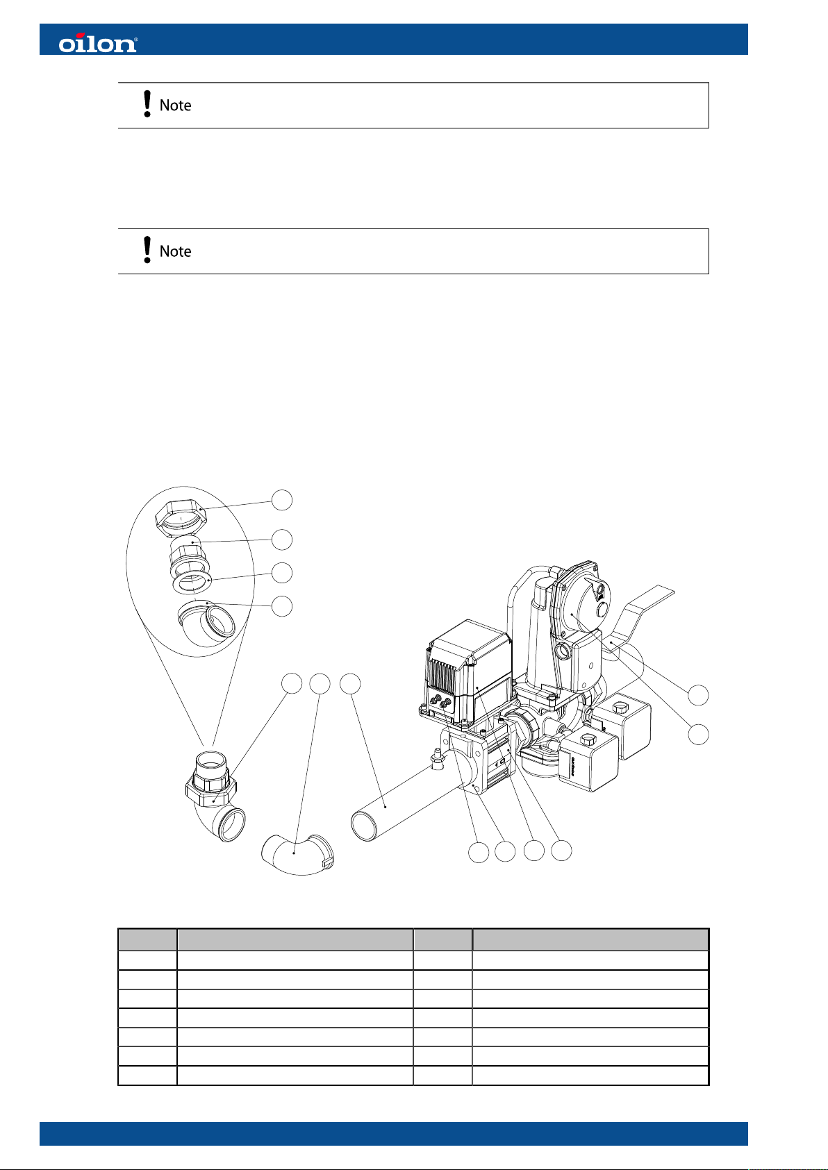
3.5 Installing gas module to burner
The gas module consists of a double solenoid valve, gas pipe, elbow fitting, and
an adjustable elbow fitting. The parts are delivered separately. The regulator valve,
servomotor, and connection flange are ready-fitted to the double solenoid valve.
The following illustration describes the gas module parts.
D046558 US ver. 1
4.3
4.1
4.4
4.2
4
2
3
1.3
1.5
1.1
1.4
1.2
1
Pos. Item Pos. Item
1 Gas valve assembly 2 Gas inlet pipe
1.1 Mounting flange, burner side 3 Elbow fitting
1.2 Manual shut-off valve 4 Adjustable elbow fitting
1.3 Servomotor 4.1 Coupling unit
1.4 Control valve 4.2 Elbow part
1.5 Servomotor cable 4.3 Nut
4.4 Gasket
22 (95) M5164 1640EN
The assembly may vary depending on the scope of delivery.
To assemble the gas module:
Gas module parts are connected to each other with threaded connections. Use thread
seal to seal the connections (for example Loctite 577).
1. Screw the gas inlet pipe to the mounting flange (1.1).
2. Screw the elbow fitting to the gas inlet pipe. Adjust the fitting to point straight to the
right, in gas flow direction (when gas inlet to burner is on the right).
3. Screw the elbow part (4.2) of the adjustable elbow fitting and adjust it to point
upwards.
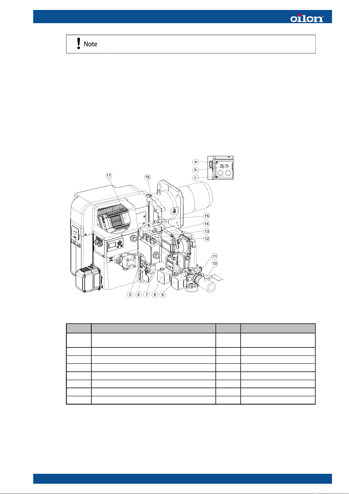
a029409 ver. 1
Pos. Item Pos. Item
5 2nd stage oil valve 13 Cable gland for gas high
pressure switch
6 1st stage oil valve 14 Gas valve cable gland
7 Main oil valve 15 Injector hoses
8 Gas high pressure switch 16 Hinge locking screw
9 Gas low pressure switch 17 Control unit
10 Manual shut-off valve a Flame detector gland
11 Gas valve assembly with pressure regulator b Gas damper servo gland
12 Cable gland for gas low pressure switch c Lead in plate
To mount the gas module to the burner:
1. Screw the coupling unit (4.1) of the adjustable elbow fitting to the burner gas frame.
The nut (4.3) must be with the coupling unit.
2. Lift the mounted gas module to the adjustable elbow fitting.
3. Check that the gasket (4.4) is in its place and undamaged.
4. Connect the gas line by screwing the nut (4.3) to the elbow part (4.2).
M5164 1640EN 23 (95)
No tape or glue is used in this threaded connection. When dismounting the burner
from the boiler, the gas line is disconnected from this connection.
5. Support the mounted gas assembly to eliminate any torsional tension.
To connect the servomotor cable to the burner control unit:
1. Remove gas damper servo gland (b) from the lead in plate (c).
2. Push the servomotor plug through the lead-in plate hole and lead the plug to the
control unit terminal X33.
3. Push the plug into the connector.
4. Pull excess length of the cable into the burner but leave a loop of cable outside to
enable the burner to be swung open.
5. Re-attach the gland (b)
To open the burner:
You can open the burner from its hinged joint, for example, to adjust the ignition
electrodes or to change or clean nozzles.
1. Switch off the power from the burner by turning the control switch.
2. Close the gas supply from the gas shut-off valve.
3. Close the oil supply from the oil shut-off valve.
4. Detach the oil hoses (15) other end from the connector.
Clean the possible oil dripping from the oil line with oil soaking fabric, for example.
5. Open the hinged flange locking screw (16).
Now you can open the burner from the hinged joint.
When closing the burner, perform the steps in reverse order.
To detach the burner from the boiler:
1. Switch off the power from the burner by turning the control switch
2. Close the gas supply from the gas shut-off valve.
3. Close the oil supply from the oil shut-off valve.
If needed, open the burner oil line from the suction and return hoses. Clean the
possible oil dripping from the oil line for example with oil soaking fabric.
4. Detach the electrical plugs from the gas valve.
5. Detach the servomotor cable (1.5) from the burner control unit (17).
For more instructions, see step 2 in section To connect the servomotor cable to the
burner control unit.
6. Open the gas supply line from the connection of the adjustable elbow fitting.
For more instructions, see step 2 in section To mount the gas module to the burner.
7. Support the burner on solid platform and detach the burner tightening screws.
8. Pull the burner out from the boiler.
When attaching the burner to the boiler, perform the steps in reverse order.
When pushing the burner to the boiler, check that the insulating material
around the combustion head is undamaged and in its place.
Check that gas and oil lines are leak-proof before taking the burner into
use again.
24 (95) M5164 1640EN
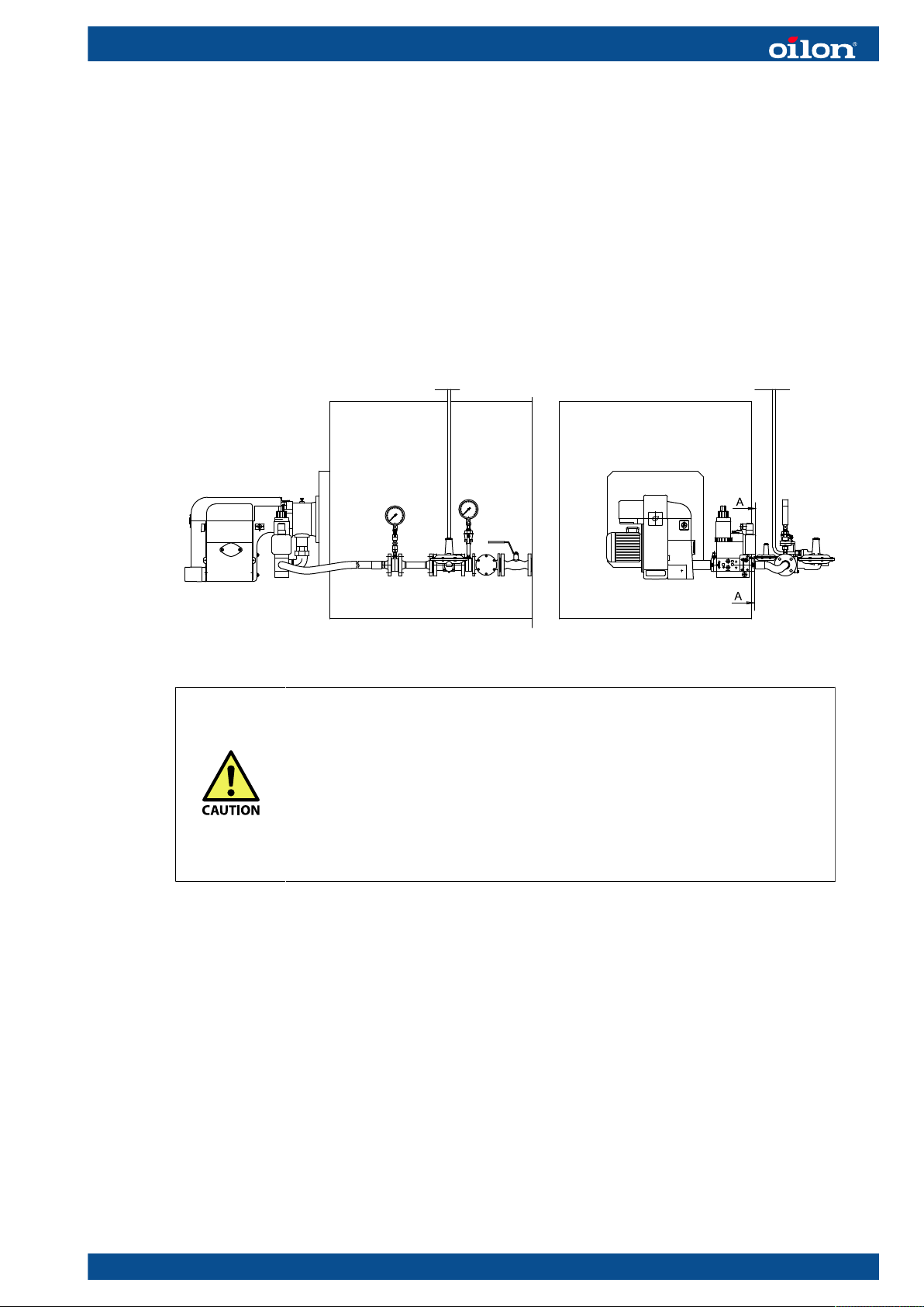
3.6 Installing burner to gas supply line
Supply line
If necessary, decrease the gas pressure with pressure regulating assembly. The gas
supply line after the pressure regulator must be of the same size or one size larger
than the burner’s gas pressure regulating assembly. The gas valve capacity adjustment
disc must be upwards. In installation, observe the valve manufacturer’s instructions.
As standard, the gas connection to the burner is from the right side. The valves shown
in the following example may vary from those delivered.
B352U ver. 3
● Install gas pipings according to the regulations of local public
authority.
● Check that there is a separate filter before gas equipment.
● Prior to installing gas pressure regulator block to piping, use
compressed air to blow supply piping clean.
● Clean and check piping prior to the installation of gas pressure
regulating assembly.
● Install gas valve so that no mechanical stress is directed to it.
● Vent gas piping before the first start-up.
To vent gas pipe:
1. Lead pipe to an open outdoor location either from the gas valve or from the blow-off
valve fixed to the pipe.
2. Open the blow-off valve.
3. Open the ball valve slowly in main supply line and fill piping with gas.
4. Close the blow-off valve.
3.7 Installing gas pressure regulating assembly
Installing pressure regulator
Consider the following factors when selecting pressure regulator:
M5164 1640EN 25 (95)
● gas supply pressure
● secondary pressure
● the quantity of gas to be combusted
● type of gas
If the gas inlet pressure is higher than the Pmax. value given in the burner technical
data, reduce the gas inlet pressure in regulating assembly. Also, if the gas inlet
pressure is not stable, stabilize the pressure with pressure regulator. If pressure
regulator is not equipped with safety relief valve and safety shut-off valve, they
must be installed according to the instructions given by the manufacturer. Also any
impulse tubes must be installed according to the instructions given by the regulator
manufacturer.
Installing safety relief valve and safety shut-off valve
Check that the safety relief valve is dimensioned so that the safety shut-off valve does
not release if the burner shuts down at full load. The burner may be shut down for
example due to mains interruption. Set the safety relief valve to open at an approx.
30% higher pressure than the secondary pressure aka pressure after the regulator.
Set the safety shut-off valve to closed position at an approx. 60 % higher pressure than
the secondary pressure. Closing the pressure of the safety shut-off valve must not
exceed the Pmax. pressure.
Prerequisites for manual shut-off valve
The gas pressure regulating assembly must be equipped with a manual shut-off valve
(pos. 2 in the diagram below). The valve must fulfill the following requirements:
● The flow cross-sectional area must be at least of the same size as the nominal size
of the gas pressure regulating assembly.
● The valve must be of such type that it can be closed quickly (for example, inversion
90°). It must also be easily accessible but protected from unintentional use.
● Pressure endurance of the valve must be at least 1.5 times the supply pressure,
and it must be equipped with mechanical limiters in open and closed positions.
● The open and closed positions must be marked separately, if it is not evident from
the valve structure.
The valve is not necessarily included in the burner delivery.
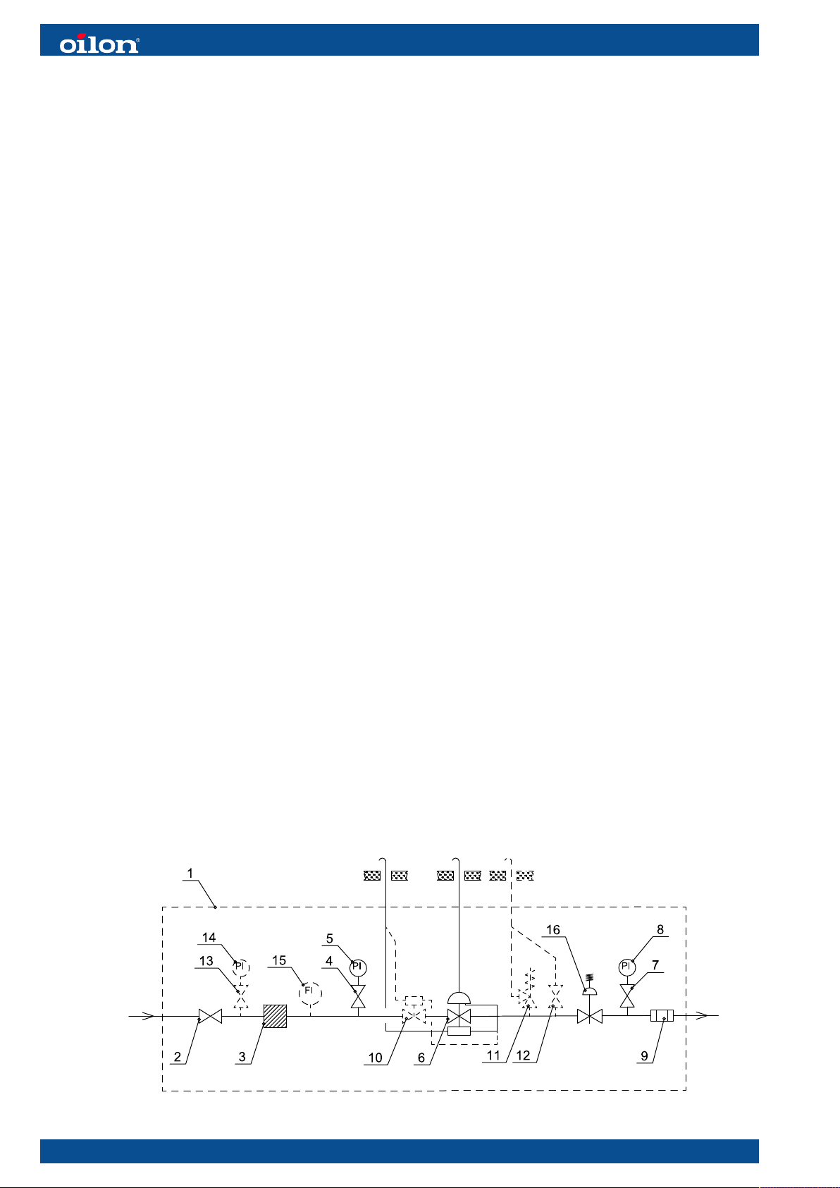
Example of gas pressure regulating assembly
B311Z ver. 4
26 (95) M5164 1640EN
Pos. Item Pos. Item
1 Gas pressure regulating assembly 9 Bellows compensator/gas hose
2 Ball valve 10 Safety shut-off valve, if not incl. in press.
regulator
3 Gas filter 11 Safety relief valve, if not incl. in press.
regulator
4 Pressure gauge valve 12 Blow-off, when necessary
5 Pressure gauge, high pressure 13 Pressure gauge valve, when necessary
6 Pressure regulator with safety shut-off
valve and safety relief valve
7 Pressure gauge valve 15 Fuel flow meter, can also be on low
8 Pressure gauge, low pressure 16 Pressure regulator
14 Pressure gauge, high pressure, when
necessary
pressure side, when necessary
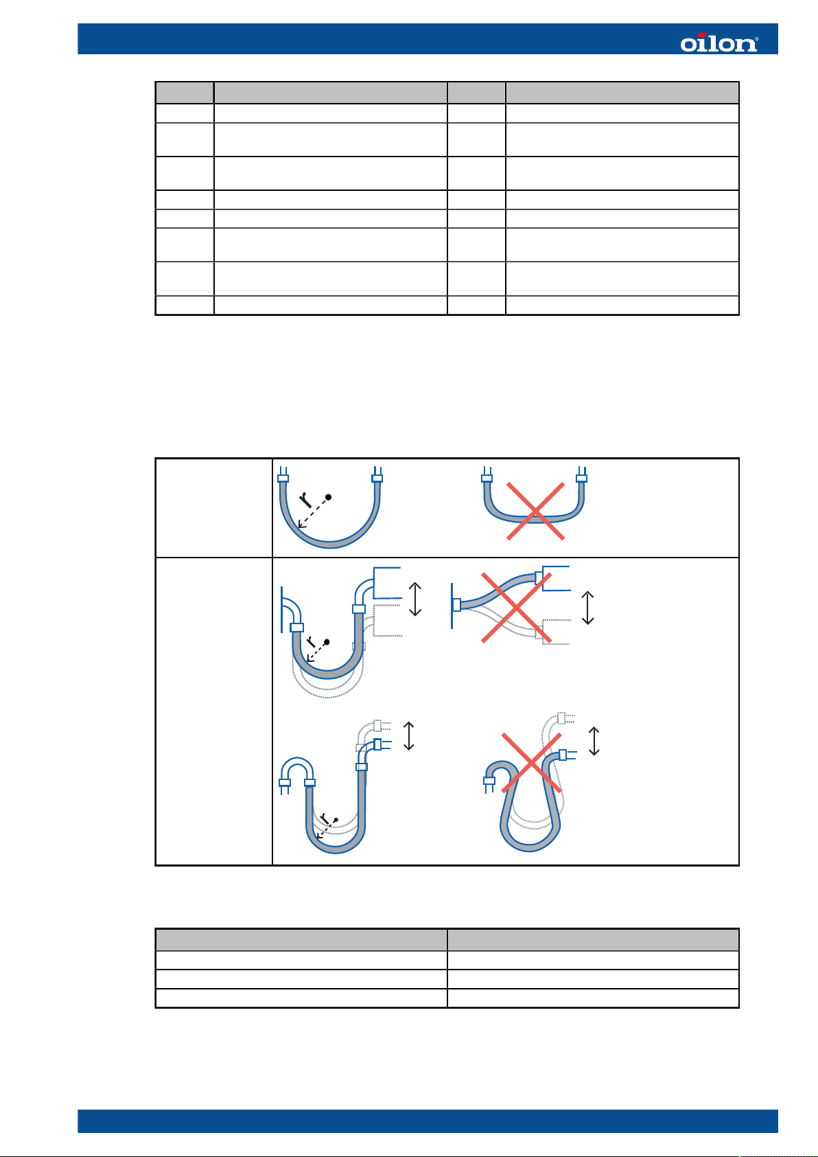
3.8 Installing hoses
Avoid torsion stress on hoses
Leave neutral hose
ends long enough
Use rigid pipe
bends when
necessary
Minimum bend radius
Hose diameter Minimum bend radius ( r )
Ø 12 130 mm
Ø 15 130 mm
Ø 22 170 mm
M5164 1640EN 27 (95)
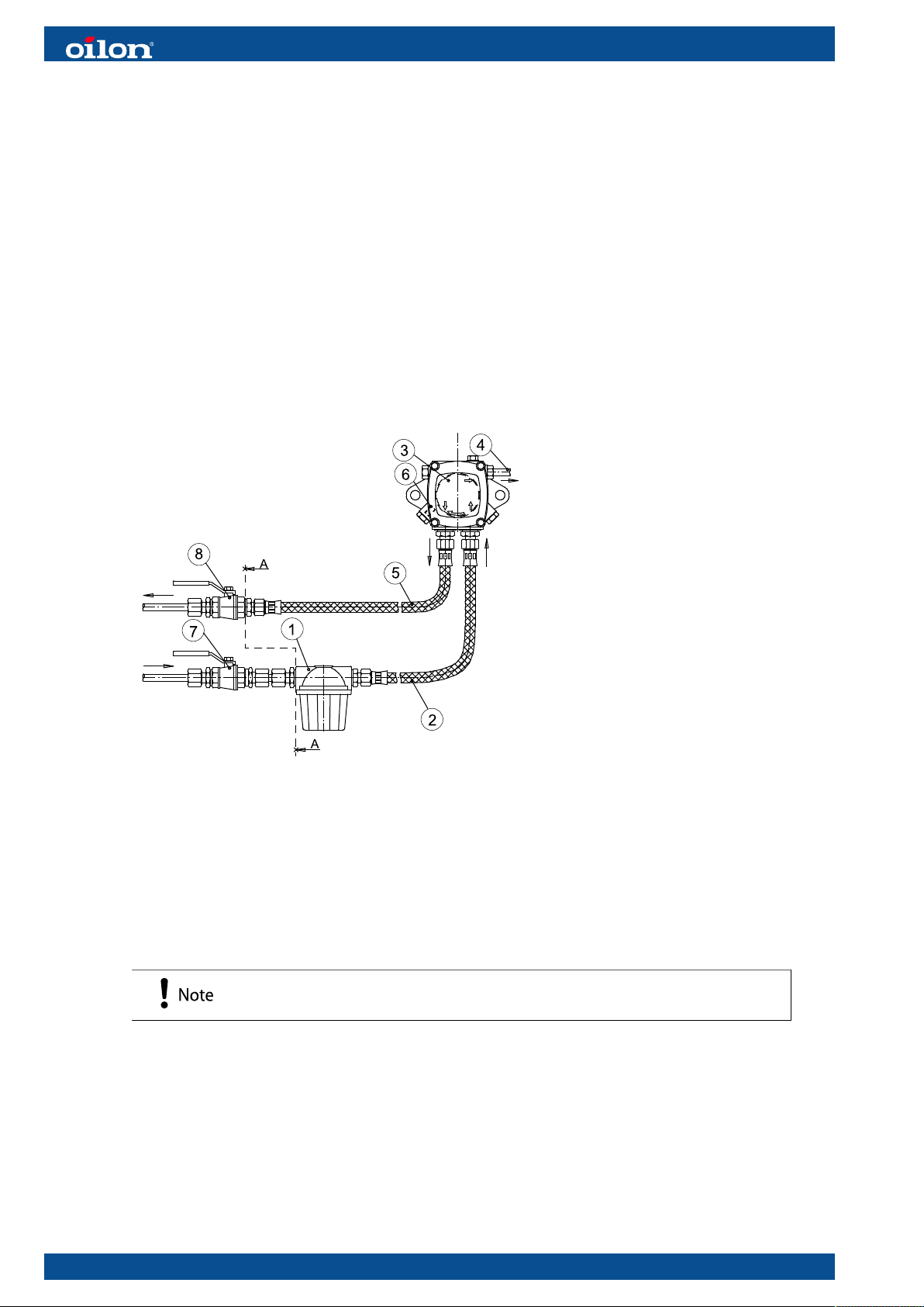
3.9 Oil piping
Oil piping manual shut-off valve
The oil supply piping must be equipped with a manual shut-off valve. The flow area
of the valve must correspond to the remaining oil piping. The valve must be of quickly
closable type (for example, inversion 90°). It must also be easily accessible but
protected from unintentional use. The valve is not necessarily included in the burner
delivery.
The manual shut-off valve must be according to UL 842, or equivalent nationally
recognized manual valve safety standard.
1 Filter
2 Oil hose, suction
3 Oil pump
4 Pressure pipe (to nozzle)
5 Oil hose, return
6 By-pass plug
7 Shut-off valve
8 Shut-off valve
A - A Delivery limit
A-429T ver. 2
Oil pipe dimensions for AJ pumps
The oil tank and the oil pipes must be installed to avoid the risk of the oil cooling below
cloud point. The cloud point of heating oil depends on the oil quality. If the oil is allowed
to cool to the cloud point, valves and filters will block. The most suitable oil temperature
is +15°C–+25 °C / + 59 °F–77 °F.
The viscosity of oil coming to the burner must be from 4 to 12 mm²/s
(cSt).
28 (95) M5164 1640EN
 Loading...