

Oilon Geopro RE Operation Manual
RE010070948EN
Operation manual
Geopro RE
Read these instructions carefully!


Contents
1.
Introduction ....................................................................................................................................4
2. Ground source heat pump operation principle...............................................................................5
2.1. RE ground source heat pump operation principle...............................................................6
2.2. Collecting heat.....................................................................................................................6
2.3. Coefficient of perfomance....................................................................................................7
2.4. Sizing heat pump.................................................................................................................7
3. Geopro controller operation...........................................................................................................8
3.1. Operating display functions .................................................................................................8
3.2. Operation.............................................................................................................................9
3.3. Basic operation....................................................................................................................9
3.4. Additional equipment control .............................................................................................12
3.5. User menu levels and factory settings...............................................................................13
3.3.1. Checking pump status and temperatures...............................................................9
3.3.2. Time and date settings............................................................................................9
3.3.3. Language settings...................................................................................................9
3.3.4. Changing room temperature settings ...................................................................10
3.3.5. Changing heating circuit operating mode.............................................................10
3.3.6. Changing heating curve........................................................................................10
3.3.7. Setting holiday heating circuit...............................................................................11
3.3.8. Adjusting domestic hot water temperature and mode..........................................11
3.3.9. Domestic hot water forced charge........................................................................11
3.3.10. Optional time program ..........................................................................................11
3.4.1. Cooling circuit 1 ....................................................................................................12
3.4.2. Solar heating.........................................................................................................12
3.4.3. Swimming pool......................................................................................................12
4. Maintenance.................................................................................................................................17
4.1. Cleaning collector circuit filter............................................................................................17
4.2. Troubleshooting.................................................................................................................18

1. Introduction
These instructions are made for Geopro –ground source heat pump user.
Remember to ask installator to fill in implementation record, which is returned to
manufacturer. Installation report is prerequisite for manufacturer quarantee.
Read these instructions carefully before using the device. Given instructions must be
followed.
Throughout this manual, the following three symbols are used to point out very
important information.
WARNING! A warning alerts you to possible danger to person, if the instructions are
not followed
CAUTION! A caution alerts you to something, that has the potential to cause
damage to component, device, process or surroundings, if the instructions are not
followed.
Note!
A note points out information of special interest.
KEEP OPERATION MANUAL NEAR THE DEVICE!
RE010070948EN 4/23
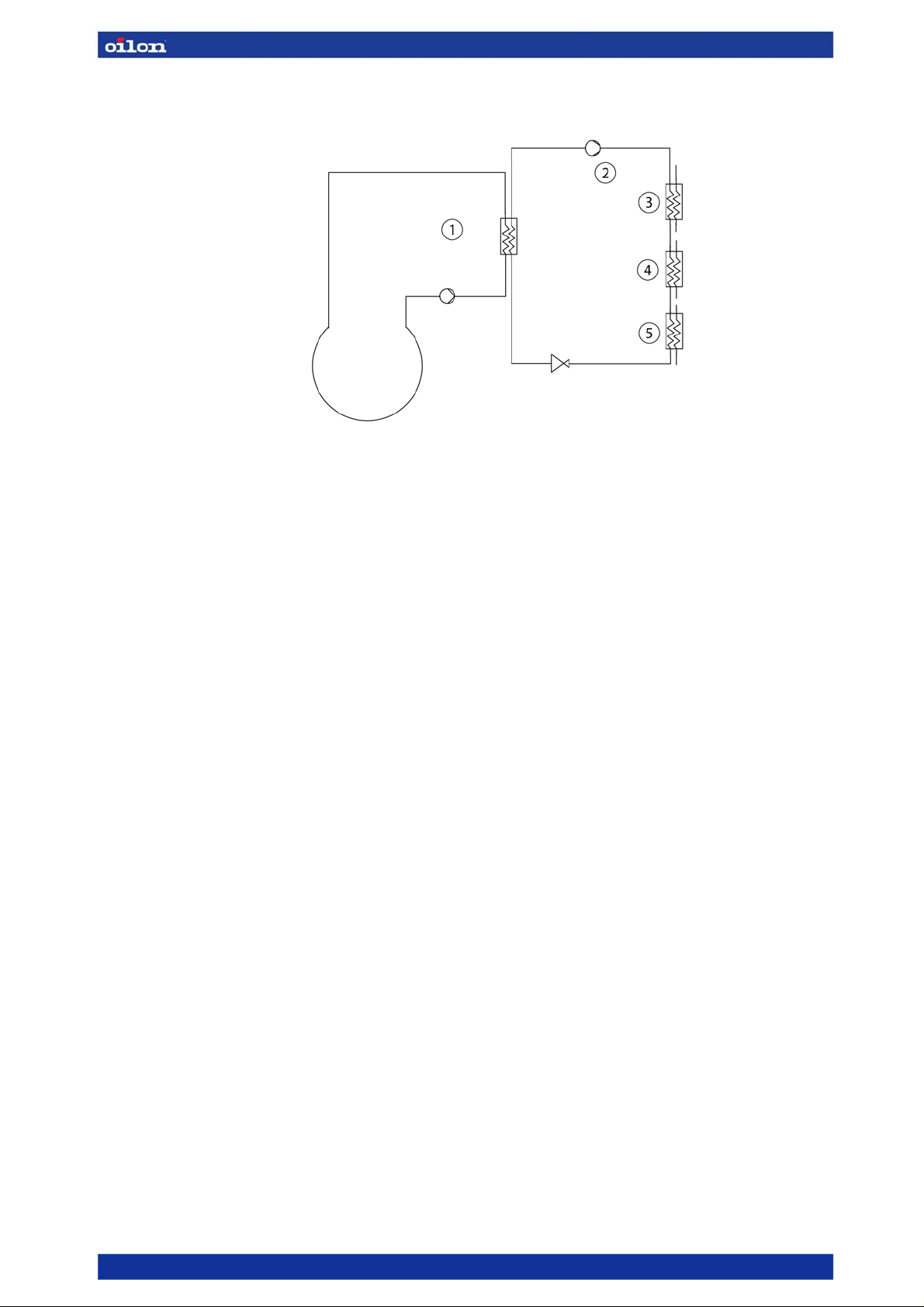
2. Ground source heat pump operation principle
1. Vaporiser
2. Compressor
3. Superheating exhausting
4. Condenser
5. Subcooler
Image 1. Ground source heat pump operating principle.
Heat pump unit operation is based on vaporisation and circulation of refrigerant in heat pump.
Refrigerant vaporisation requires heat energy. Required heat energy is collected using heat
collector piping located in the ground or waters. Refrigerant boils into gas at vaporiser, binds
heat into itself and moves on to compressor.
Compressor absorbs refrigerant gas created in vaporiser, and compresses it into high pressure
causing steam temperature to rise. Steam is condensated into liquid in condensator, and
energy is saved at required heating level. Then condensated refrigerant pressure is reduced
into compressor suction pressure level at expansion valve, causing part of the refrigerant to
vaporise and cool down the whole flow into a level that can store energy from the ground. Then
the cycle starts over.
Superheating capacity is transferred into heating network water with separate heat exchanger.
In de-superheating heat exchanger, steam is cooled using water flow, causing steam
temperature to lower but keeping refrigerant from condensating into liquid. In condensator
refrigerant is condensated into liquid at nearly standard temperature. Heat energy discharged
from condensing is utilised to warm up heating network water. Superheating pumps operate in
advantageous conditions for ground heat technique because domestic hot water is not
produced at high pressure level.
RE010070948EN 5/23
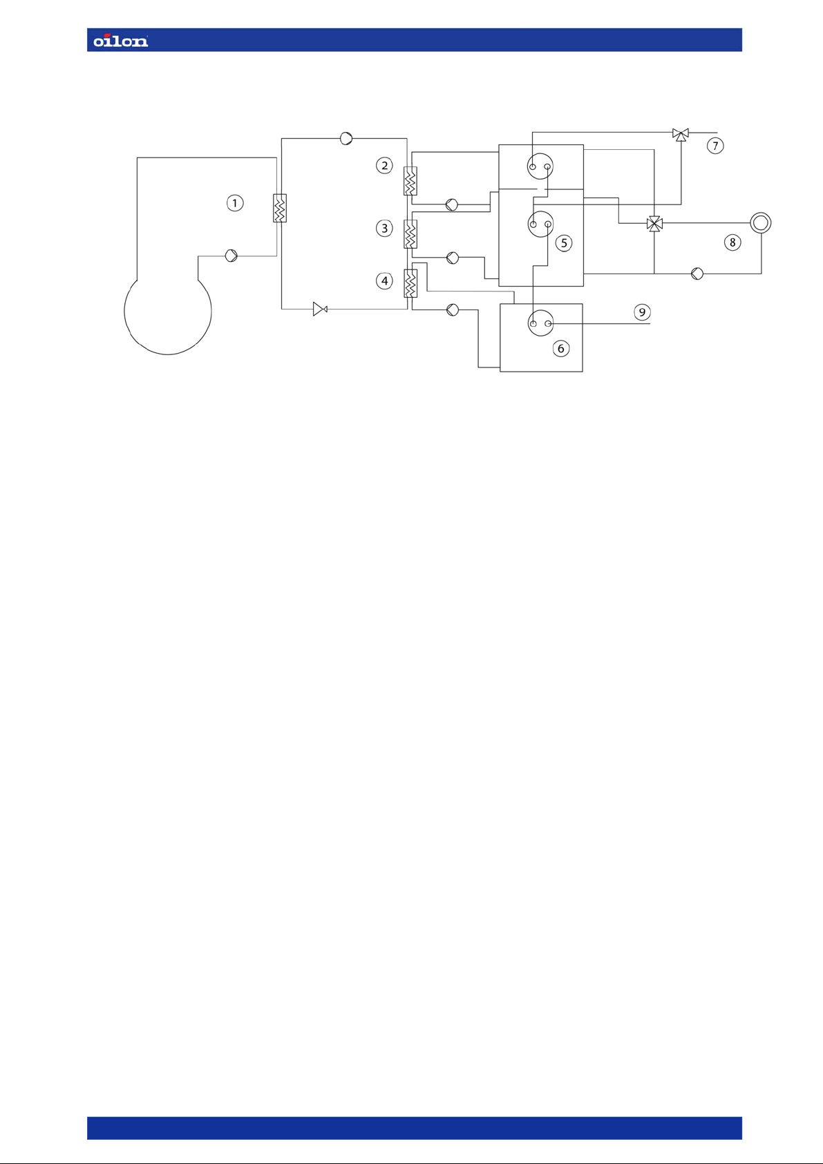
2.1. RE ground source heat pump operation principle
1. Vaporiser 6. Subcooler buffer tank
2. Compressor, de-superheating, option 7. Warm water
3. Condenser 8. HC 1 heating circuit
4. Sub cooler, option 9. Cold water
5. Superheating buffer tank
Image2. RE ground source heat pump operation principle.
RE ground source heat pump standard model does not include super heater exchanger or
subcooler. They can be ordered separately as option.
Subcooler capacity can be max. 10 % of total capacity, so it cannot be used to warm up large
areas. It can be used for heating in location with low temperature such as swimming pool,
terrace or garage. However, utilising subcooler capacity is cost-effective. It does not increase
compressor input, which causes slight COP improvement.
RE pump is always connected to separate buffer tank or buffer tanks. Domestic hot water is
warmed up in domestic hot water loops in buffer tank. Preheating loop can be located in the
middle of the same buffer tank or in another buffer tank. Rest of the heating is carried out by
loop in the upper part of the buffer tank or loop in separate domestic hot water buffer tank.
2.2. Collecting heat
RE ground source heat pump’s heat source is usually a drilled well. The number and depth of
wells depend on heating demand. Soil or waters can also be used as heat source. Heat is
collected from soil using horizontal piping in 1…1,2 m depth. When using waters the piping is
anchored to the bottom. Yet RE pump heating demand is so large that usually drilled well is
used as heat source.
Heat collector piping material is normal plastic water supply pipe. Circulating fluid is anti-freeze
mixture of industrial alcohol (30 %) and water (70 %). In some cases also potassium calcium
formiate solution or betaine based solution can be used.
Ground circuit fluid warms up about 3 degrees during circulation. Collected heat is used to
vaporise refrigerant in heat pump unit.
Horizontal piping requires applicable soil type and sufficient land area for piping. Applicable soil
types are fine grained and most, such as clay or silt.
Drilled well is suitable for all locations except locations where solid rock goes deep
underground.
When piping is installed into waters, building should be located sufficiently close to shoreline,
preferably less than 50 m away. Waters should also be sufficiently deep, over 2 m right from
shore.
RE010070948EN 6/23

2.3. Coefficient of perfomance
Heat pump efficiency ratio is measured with coefficient of performance, COP. COP indicates the
amount of heat energy transferred into compressor in relation to used electrical energy.
COP depends largely on heat source and heating network temperatures. The highest possible
heat source temperature and the lowest possible supply water temperature improve efficiency
ratio.
When using heat pump, floor heating is more reasonable option than radiator heating because floor
heating requires lower supply water temperature.
2.4. Sizing heat pump
Heat pump can be sized up to operate at partial or full capacity. With partial capacity heat pump
maximum capacity is sized up to correspond 60…80 % of building maximum heating demand.
Then heat pump produces 85…98 % of buildings annual heat energy demand. With partial
capacity heat pump operates for long time periods which reduces compressor stops and startups. This decreases compressor wearing. During hardest cold periods at winter additional
capacity can be obtained from secondary heating source, for example from buffer tank in-built
electric heater or oil boiler.
With full capacity, heat pump is sized up according to buildings maximum capacity demand, and
is practically little over sized.
RE010070948EN 7/23
 Loading...