

OilGear PVM-011, PVM-014, PVM-046, PVM-022, PVM-065 Service Manual
...
Bulletin 947070-B
OILGEAR TYPE “PVM” PUMPS -
-011/-014/-022/-025/-034/-046/
-064/-065/-075/-076/-098/-130
SERVICE INSTRUCTIONS
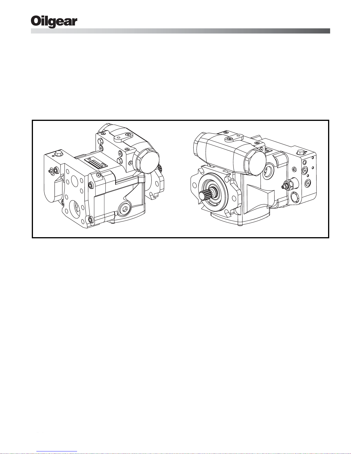
Figure 1. Typical Oilgear “PVM” Open Loop Pump
PURPOSE OF INSTRUCTIONS
These instructions will simplify the installation,
operation, maintenance and troubleshooting of
Oilgear type “PVM” pumps.
REFERENCE MATERIAL
Fluid Recommendations.....................................................................................Bulletin 90000
Contamination Evaluation Guide.........................................................................Bulletin 90004
Filtration Recommendations...............................................................................Bulletin 90007
Piping Information...............................................................................................Bulletin 90011
Installation of Vertically Mounted Axial Piston Units ...........................................Bulletin 90014
PVM Open Loop Pumps Sales Brochure........................................................Bulletin 47070-B
OILG0173
Become familiar with the construction, principle of
operation and characteristics of your pump to help
you attain satisfactory performance, reduce shutdown and increase the pump's service life. Some
pumps have been modified from those described in
this bulletin and other changes may be made
without notice.
Bulletin 947070-B THE OILGEAR COMPANY 1
Revised November, 2004
THE OILGEAR COMPANY
2300 South 51st Street
Milwaukee, Wisconsin 53219
Bulletin 947070-B
Safety First
Read and understand this entire instruction sheet
before repairing, or adjusting your Oilgear product.
Those who use and maintain this equipment must
be thoroughly trained and familiar with the product.
If incorrectly used or maintained, this product and
its equipment can cause severe injury.
SAFETY SYMBOLS
The following signal words are used in this
instruction sheet to identify areas of concern where
your safety may be involved. Carefully read the text
and observe any instructions provided to ensure
your safety.
DANGER
! !
THIS SIGNAL WORD INDICATES AN IMMINENTLY HAZARDOUS SITUATION WHICH,
IF NOT AVOIDED, WILL RESULT IN DEATH
OR SERIOUS INJURY.
WARNING
!
This signal word indicates a potentially
hazardous situation which, if not avoided,
could result in death or serious injury.
CAUTION
This signal wor d indicate s that a pote ntiall y
hazardous situation exists which, if not
avoided, may result in damage to
equipment or minor personal injury.
NOTE
While not directly relevant to the topic being
discussed, the NOTE is used to emphasize
information provided, or provide additional
information which may be of benefit.
WARNING
!
This service information is designed for
the maintenance of your Oilgear product.
It contains the information on the correct
procedures determined by Oilgear for the
safe manner of servicing. Always keep
this instruction sheet in a location where it
is readily available for the persons who
use and maintain the product. Additional
copies of this instruction sheet are
available through the Oilgear Company.
Or visit our website: www.oilgear.com.
Please contact us if you have any
questions regarding the information in
this instruction bulletin.
NOTE
The cleanliness of working on this pump or
the hydraulic system is extremely
important to the safety and reliability of the
pump and the system. Always make sure
the fittings are clean on the outside before
removing them from their connections, are
capped and plugged when removed and
placed in a clean rag or container until they
are reinstalled.
WARNING
!
Some service operations may require
special tools or equipment. If you require
information on these items, please contact
Oilgear before attempting these repairs
and service operations.
WARNING
!
Read, understand, and follow the safety
guidelines, dangers, and warnings
contained in this instruction sheet to
promote reliable operation and prevent
serious personal injury.
WARNING
!
DO NOT attempt to service this machinery
in an environment where safety regulations
are not established and in place.
WARNING
!
DO NOT operate the hydraulic system if a
leak is present. Serious injury may result.
WARNING
!
Hydraulic systems operate under very high
pressure. Hydraulic fluid escaping from a
pressurized system can penetrate
unprotected body tissue. DO NOT inspect
for hydrauli c leaks with ba re hands or o ther
exposed body parts. As a minimum, wear
leather gloves prior to inspecting for leaks
and use cardboard or wood. If leaks are
present, relieve pressure and allow system
to cool prior to servicing. If injured by
escaping hydraulic oil, contact a physician
immediately. Serious complications may
arise if not treated immediately. If you have
questions regarding inspecting for
hydraulic leaks, please contact Oilgear
prior to servicing.
2 THE OILGEAR COMPANY Bulletin 947070-B
© 1993 THE OILGEAR COMPANY - ALL RIGHTS RESERVED
Safety First
WARNING
!
Hydraulic hoses and tubing must be
inspected on a daily basis for leaks, cuts,
abrasions, damage and improper
clearance along any mounting frame for
hidden damage before the unit is put into
service. Replace damaged hoses or hoses
you suspect are damaged before the
system is returned to service! Hoses must
be replaced every two years. Failure to
properly inspect and maintain the system
may result in serious injury.
WARNING
!
Hydraulic systems are hot. DO NOT
TOUCH! Serious personal injury may
result from hot oil. When you have
completed working on the hydraulic
system, thoroughly clean any spilled oil
from the equipment. Do not spill any
hydraulic fluids on the ground. Clean any
hydraulic fluids from your skin as soon as
you have completed maintenance and
repairs. Dispose of used oil and system
filters as required by law.
WARNING
!
Hydraulic cylinders can be holding a
function in a certain position when
thepump is OFF. An example of this is a
function being held in the lift or partial lift
position by the cylinders. If a hydraulic
line is removed or the hydraulic circuits or
controls are being worked on, gravity may
allow the function being held in position to
drop. All workers and personnel must
remain clear of these areas when working
on or operating the hydraulic system.
Block and secure all devices and
functions which apply before beginning
work or operation. Failure to comply with
this can result in serious injury or death.
WARNING
!
Any hydraulic pipe which is replaced must
conform to SAE J1065 specifications. If
incorrect hydraulic pipe is installed, the
hydraulic system may fail, causing
serious injury. Damaged or leaking
fittings, pipes or hoses must be replaced
before the system is returned to service.
WARNING
!
Use correct hoses, fittings, and adapters
with the correct SAE rating when
replacing hoses to prevent possible
serious injury. Always replace hoses,
fittings, and adapters with replacements
that have a proper, suitable, working
pressure rating. Replacement hoses must
be of the correct length and must comply
with the hose manufacturer’s and
Oilgear’s installation guidelines and
recommendations.
WARNING
!
Hydraulic hoses have the SAE ratings
marked on the hose to assist you in
selecting the correct hose. The same manufacturer must supply any replacement
hydraulic hoses and fitting assemblies. As
an example: Brand “X” hose and brand “Y”
fitting will not normally be compatible. No
“Twist” is allowed in the hydraulic hoses.
“Twist” may result in premature hose
failure. This can cause serious injury.
Please contact Oilgear for assistance when
required.
WARNING
!
DO NOT heat hydraulic pipe. The carbon
content of this steel tube is such that if
heated for bending, and either water or air
quenched, the pipe may lose its ductility
and thereby be subject to failure under
high pressure or hydraulic chock
conditions. Serious injury can result.
Damaged or leaking pipes must be
replaced before the system is returned to
service. Please contact Oilgear if you
require assistance or have questions.
WARNING
!
All hydraulic pressure must be relieved
from the hydraulic system prior to re moving
any components from the system. To
relieve the hydraulic pressure from the
hydraulic system, turn off the motor and
operate the control panel with the key in the
ON position. Failure to comply can result in
serious injury. If you have any questions
concerning relieving the hydraulic pressure
from the system, please contact Oilgear.
Bulletin 947070-B THE OILGEAR COMPANY 3

Safety First
WARNING
!
Hydraulic components can be heavy. Use
caution while lifting these components.
Serious personal injury can be avoided
with proper handling of the components.
WARNING
!
Please contact Oilgear if you require
assistance, when performing hydraulic
test procedures, use the proper hydraulic
gauges. Installing an incorrect test gauge
could result in serious injury if the gauge
fails. Use properly rated hydraulic hoses
to allow the test gauge to be read away
from moving parts and functions.
WARNING
!
Increasing hydraulic pressure beyond the
recommendations may result in serious
damage to the pump and system or
serious personal injury and may void the
Oilgear Warranty. If you have questions
concerning hydraulic pressures or testing
procedures, please contact Oilgear before
attempting the test procedures or making
adjustments.
WARNING
!
Any Oilgear pump safety decals must be
replaced anytime they are damaged,
missing, or cannot be read clearly. Failure
to have proper decals in place can result
in serious injury or death. (If you require
safety decals, please contact Oilgear for
replacement safety decals, at no charge.)
WARNING
!
Be sure everyone is clear of the area
around the hydraulic system before
operating after servicing. Remain attentive
at all times when operating to check your
work until you are completely sure it is
safe to return to service. Failure to heed
this warning may result in serious
personal injury or death.
WARNING
!
Wear the proper protective clothing when
operating, servicing or maintaining the
hydraulic system or the Oilgear pump. Wear
the correct protective gear, safety glasses,
gloves, and safety shoes. Serious injury
can result without proper protective gear.
WARNING
!
An Oilgear pump must not be modified in
any way without authorization from
Oilgear. Modifications may not comply
with safety standards, including ANSI
safety standards, and may result in
serious personal injury. Please contact
Oilgear if you require assistance.
WARNING
!
DO NOT enter under hydraulic supported
equipment unless they are fully supported
or blocked. F ailure to follow this procedure
can result in serious injury or death.
WARNING
!
Make sure to keep hands and feet and
other parts of your body clear of revolving
or moving parts. Failure to comply can
cause serious injury.
WARNING
!
DO NOT wear watches, rings, or jewelry
while working with electrical and mechanical equipment. These items can be hazardous and can cause serious and painful
injuries if they come into contact with electrical wires, moving parts, or hydraulic
equipment.
4 THE OILGEAR COMPANY Bulletin 947070-B

Service Instructions
PREPARATION AND
INSTALLATION
MOUNTING
Pump Without Reservoir - The pump can be
mounted in any position. But, the recommended
mounting position is with the driveshaft on a
horizontal plane. Secure the pump to a rigid
mounting surface.
Pump With Reservoir - These pumps are usually
fully piped and equipped. It may be necessary to
connect to a super-charge circuit when used.
Mount reservoir on level foundation with the
reservoir bottom at least six inches above floor
level to facilitate fluid changes.
PIPING AND FITTINGS
Refer to the referenced Oilgear Piping Information
Bulletin 90011 and individual circuit diagram before
connecting the pump to the system. Inlet velocity
must not exceed 5 fps (1,5 mps). Inlet should be
unrestricted and have a minimum of fittings.
NOTE
Horizontal Mounting - Arrange line from the highest
“case drain” or “alternate case drain” so the case
remains full of fluid (non-siphoning). Case pressure
must be less than 25 psi (1,7 bar). For higher case
pressures and the special shaft seals required,
contact our Customer Service. Each drain line
must be a separate line, unrestricted, full sized and
connected directly to the reservoir below the lowest
fluid level. Make provisions for opening this line
without draining (siphoning) reservoir.
Vertical Mounting - Refer to referenced Oilgear
“Installation of Vertically Mounted Axial Piston
Units,” Bulletin 90014.
DO NOT use an inlet strainer.
WARNING
!
Running the pump in NEUTRAL position
(zero delivery) for extended periods
without a supercharge circuit can damage
the pump. The system and pump must be
protected against overloads by separate
high pressure relief valves. Install bleed
valve(s) at the highest point(s) in system.
POWER
Power is required in proportion to volume and
pressure used. Motor size recommendations for
specific applications can be obtained from The
Oilgear Company. Standard low starting torque
motors are suitable for most applications.
CAUTION
DO NOT start or stop unit under load
unless system is approved by Oilgear. It
may be necessary to provide delivery
bypass in some circuits.
DRIVE
V erify rotation direction plate on the pump 's housing.
Clockwise pumps must be driven clockwise and
counterclockwise pumps must be driven
counterclockwise. Use direct drive coupling. Size
and install coupling per manufacturer's instructions.
CAUTION
DO NOT drive the coupling onto the pump
driveshaft. If it is too tight, it may be
necessary to heat coupling for installation.
Refer to manufacturer's instructions.
Misalignment of pump shaft to driver's shaft should
not exceed 0.005 inches (0,13 mm) Total Indicator
Readout (TIR) in any plane.
Bulletin 947070-B THE OILGEAR COMPANY 5
FILTRATION
Keep the fluid clean at all times to ensure long life
from your hydr aulic system. Ref er to the ref erenced
Oilgear Filtration Recommendations bulletin 90007
and Oilgear Contamination Evaluation Guide
Bulletin 90004. Oilgear recommends use of a filter
in the pressure or return line. Replace filter
element(s) when the filter condition indicator
reaches change area at normal fluid temperature.
Drain and thoroughly clean filter case. Use
replacement element(s) of same beta 10 ratio
(normally a ratio of 4 with hydraulic oils).
FLUID COOLING
When the pump is operated continuously at the
rated pressure or frequently at peak load, auxiliary
cooling of the fluid may be necessary. Fluid
temperature should not exceed limits specified in
the referenced Oilgear Fluid Recommendations
Bulletin 90000.
AIR BREATHER
On most installations, an air breather is mounted
on top of fluid reservoir. It is important for the
breather to be the adequate size to allow air flow in
and out of reservoir as fluid level changes. Keep
the breather case filled to the “fluid level” mark.
About once every six months, remove cover, wash
screen in solvent and allow screen to dry, clean
and refill case to level mark and install screen.
Refer to the manufacturer's recommendations.
FLUID, FILLING AND STARTING
RECOMMENDATIONS
Refer to instruction plate on the unit, reservoir,
machine and/or reference, Fluid Recommendations
bulletin. Fire resistant fluids and phosphate ester
fluids can be used in accordance with fluid
manufacturer's recommendations .
1. Pump all fluid into reservoir through a clean
(beta 10 ratio of 4 or more) filter. Fill reservoir
to, but not above, “high level” mark on the sight
gauge.
2. Remove case drain line and fill pump case
with hydraulic fluid.
3. Turn driveshaft a few times by hand with a
spanner wrench to make sure parts rotate.
With pump under “no load” or with pump control at
NEUTRAL:
4. Turn drive unit ON and OFF several times
before allowing pump to reach full speed. The
system can usually be filled by running the
pump and operating the control.
5. The fluid level in the reservoir should decrease.
Stop the pump. DO NOT allow the fluid level to
go beyond the “low level.” If the level reaches
“low level” mark, add fluid and repeat step.
NOTE
With differential (cylinder) systems, the fluid
must not be above “high level” when the
ram is retracted or below “low level” when
extended. Bleed air from the system by
loosening connections or opening petcocks
at the highest point in the system. Close
connections or petcocks tightly when solid
stream of fluid appears.
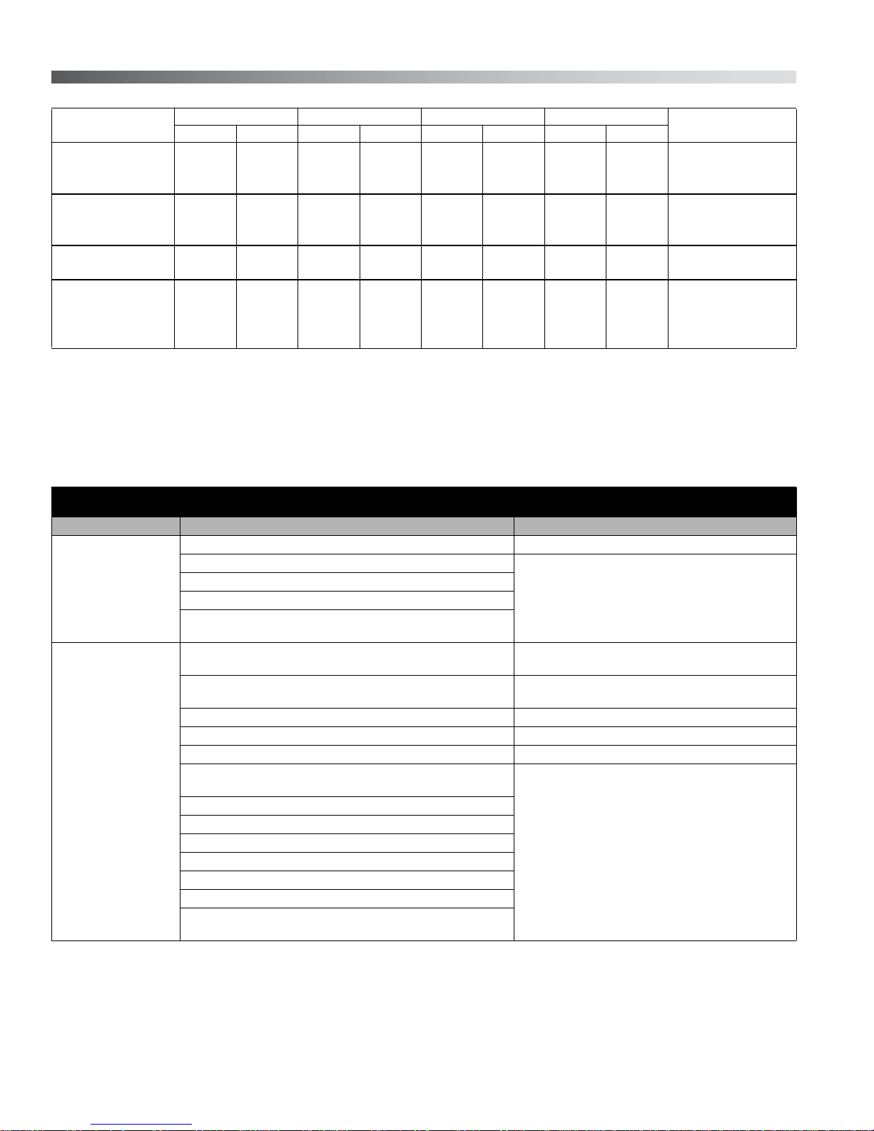
Unit PVM-011/-014/-022 PVM-025/-034/-046/-065/-075 PVM-064/-076/-098/-130
Approximate torque
to turn driveshaft
15-25 in•lb
(1,7-2,8 N•m)
6 THE OILGEAR COMPANY Bulletin 947070-B
120-180 in•lb
(13,7-20,5 N•m)
Table 1. Torque to Turn Shaft
180-260 in•lb
(20,5-29,6 N•m)

CONSTRUCTION
See Figures 11, 12 and 13.
1. A driveshaft (21) runs through the center line of
pump housing and valve plate (45) with the
pump cylinder barrel (38) splined to it.
2. A bearing (26) supports the outboard end of
the driveshaft and a bushing supports the
inboard end. (The bushing is part of valve pla te
assembly.)
3. The pump cylinder barrel is carried in a
hydrodynamic (journal type) cylinder bearing
(35).
4. The port plate (43) has two crescent shaped
ports and is located on a valve plate (45) that
has matching crescent shaped ports.
5. The pumping piston/shoe assemblies (39) in
the cylinder barrel are held against a
swashblock (29) by a shoe retainer (40).
6. The shoe retainer is held in position by the
fulcrum ball (41) which is forced outward by the
shoe retainer spring (42).
7. The spring acts against the pump cylinder
barrel, forcing it against the valve plate while
also forcing the piston shoes against the
swashblock.
8. The semi-cylindrical shaped swashblock limits
the piston stroke and can be swiveled in arc
shaped saddle bearings (30).
9. The swashblock is swiveled by a control piston
(19). Refer to PRINCIPLE OF OPERATION.
SPECIFICATIONS
NOTE
Refer to reference material, pump control
material and individual application circuit
for exceptions.
FLOW RATE
THEORETICAL
UNIT
011 0.66 10,8 3750 258,6 4250 293,1 4.3 16,3 5.6 (0,39) 8.1 (0,56) 17.2 (1,19) 3600 12.8 9,5
014 0.86 14,1 3750 258,6 4250 293,1 5.8 22,0 5.5 (0,38) 7.8 (0,54) 17.2 (1,19) 3600 16.4 12,1
022 1.35 22,1 3750 258,6 4250 293,1 9.5 36,0 8.6 (0,60) 11.4 (0,79) 23.7 (1,63) 3600 26.1 19,5
025 1.55 25,4 3750 258,6 4250 293,1 10.1 38,2 6.5 (0,45) 11.5 (0,80) - 2700 28.8 21,5
0342.06 33,8 3750 258,6 4250 293,1 14.1 53,4 5.7 (0,40) 11.0 (0,76) - 2700 37.7 28,1
046 2.83 46,4 3750 258,6 4250 293,1 19 .7 74,6 5.7 (0,40) 8.1 (0,56) - 2400 51.9 38,7
064 3.88 63,6 3750 258,6 4250 293,1 2 6 .6 100,7 7.3 (0,50) 11.4 (0,79) - 2400 70.2 52,4
065 4.00 65,5 3750 258,6 4250 293,1 27 .9 105,6 6.2 (0,43) 1 0.2 (0,70) - 3000 71.0 53,0
075 4.61 75,5 3750 258,6 4250 293
076 4.67 76,5 3750 258,6 4250 293,1 32.4 122,6 8.2 (0,57) 13.4 (0,92) - 2400 85.7 63,9
098 6.00 98,33750 258,6 4250 293,1 41.2 156,0 8.3 (0,57) 12.1 (0,83) - 2400 109.2 81,4
1307.94130,2 3750 258,6 4250 293,1 57.8 218,8 8.7 (0,60) 14.9 (1,03) - 2400 150.8 112,5
Case pressure should be less than 25 psi (1,7 bar). For hi gh er pressure, consult factory. Higher speeds availab le - consult factory.
MAXIMUM
DISPLACEMENT
in 3/rev ml/rev psi bar psi bar gpm l/mi 1800 rpm 2400 rpm 3600 rpm rpm hp kw
RATED
CONTINUOUS
PRESSURE
MAXIMUM
PRESSURE
1800 rpm rated
continuous
pressure and
14,7 psia (bar abs)
inlet condition
,1 31.3 118,5 6.5 (0,45) 10.6 (0,73)- 3000 83.8 62,5
at
MINIMUM INLET PRESSURE
psia (bar abs)
MAXIMUM
SPEED
POWER
INPUT at
rated
continuous
pressure &
1800 rpm
Table 2. All data is for ISO 46 mineral-based oil at 125°F (160 SSU).
Bulletin 947070-B THE OILGEAR COMPANY 7
Unit
PVM-011
PVM-022
PVM-025
PVM-046
PVM-065
PVM-075
PVM-064
PVM-076
PVM-098
PVM-130
Length Width Height Weight*
inches mm inches mm inches mm lbs. kg
7.95 201,9 7.28 184,9 6.63 168,4 37.5 17,0 SAE "A" 2 BoltPVM-014
9.51 241,5 9.00 228,6 8.88 225,6 73.0 33,1 SAE "B" 2/4 BoltPVM-034
10.00 254,0 9.03 229,4 8.88 225,6 75.0 34,0 SAE "B" 2/4 Bolt
11.91 302,5 10.73 272,5 10.45 265,4 136.0 61,7 SAE "C" 2/4 Bolt
For detailed dimensions, contact your Oilgear Representative.
* Weight with rear port valve plate and without maximum volume stop.
Table 3. Nominal Dimensions and Weights.
Refer to installation drawings for more detailed dimensions and port configurations.
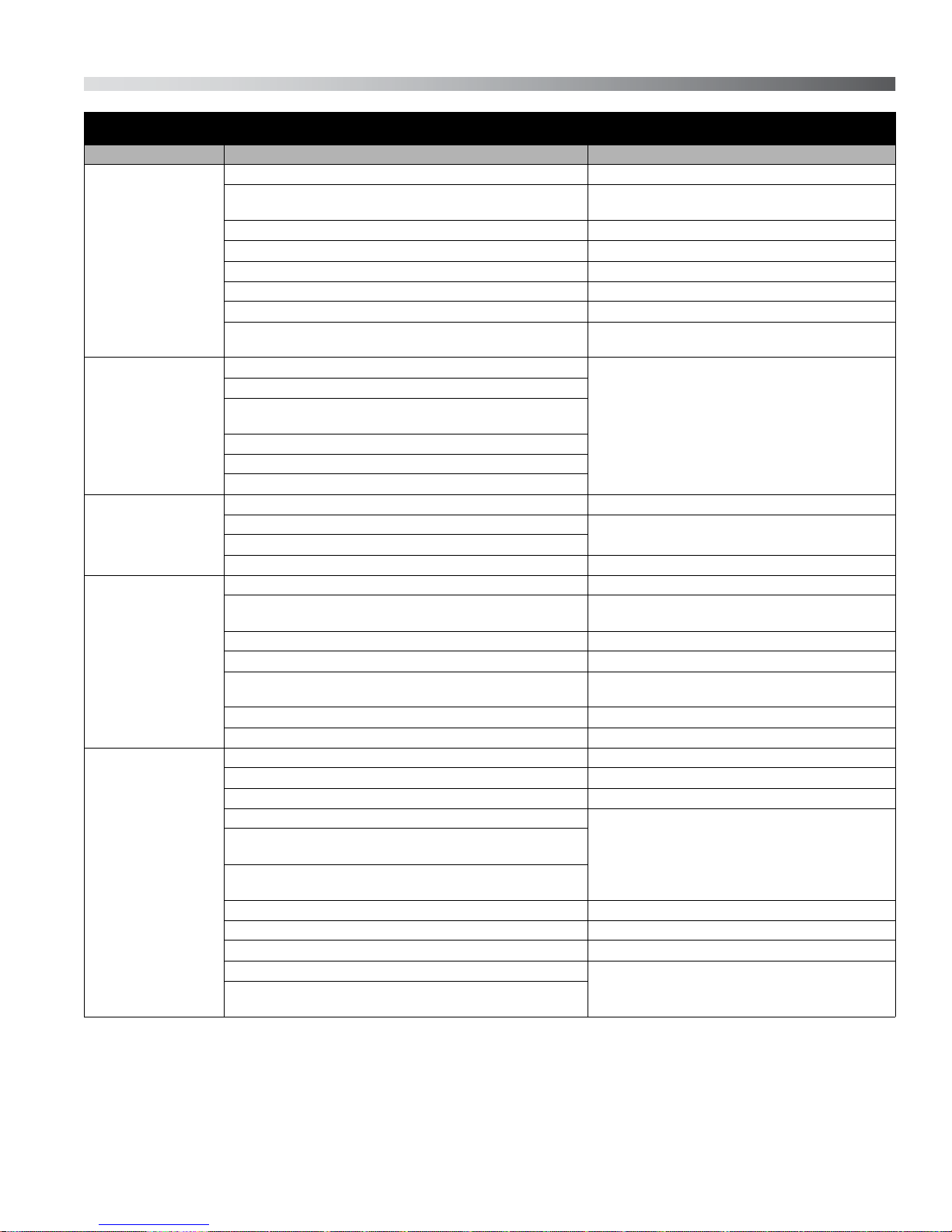
TROUBLESHOOTING
PROBLEM CAUSES REMEDY
Plugged stability orifice (OP2). Inspect. Clean out if contaminated.
PC control cartridge (55) damaged.
Unresponsive or
Sluggish Control
Insufficient Pump
Volume
Swashblock saddle bearings (30) worn or damaged.
Control piston (19) or sequence spool (54) binding in bore.
Control piston spring (20) broken, sequence valve spool spring
(53) broken.
High load sense differential pressure.
PC control cartridge damaged, stuck open.
Delivery limited by stroke limiter screw (70). Adjust stroke limiter CCW.
Obstructed suction circuit or insufficient supercharge volume. Inspect for obstruction and verify supercharge.
Insufficient drive motor speed. Check drive speed.
Worn or grooved cylinder barrel (38) and/or port plate (43) mating
surfaces.
Worn or damaged piston shoe or swashblock (29).
Worn or sticking control piston (19).
Port plate not seated against valve plate.
Worn hydrobearing (35).
Worn or broken saddle bearing (30).
O-rings leaking on plug (84) or control cartridges (55) or (83).
Worn or damaged piston and shoe assemblies (39) or piston
bores in cylinder (38).
Inspect components. Replace.
Verify that load sense differential pressure is less than
pump control setting.
Inspect. Clean out if contaminated. Replace if
necessary.
Inspect components. Replace.
Face Mounting
8 THE OILGEAR COMPANY Bulletin 947070-B
TROUBLESHOOTING
PROBLEM CAUSES REMEDY
Fluctuating load sense differential pressure. Check system flow control valve/orifice.
Irregular or
Unsteady Operation
Loss of Pressure
Excessive or High
Peak Pressure
Excessive Noise
Excessive Heating
Faulty control piston (19), sequence valve (54) or PC control
cartridge (55) operation.
Fluid level in reservoir is low or supercharge is insufficient. Verify fluid level and/or supercharge.
Air entering hydraulic system. Inspect system for leak.
Low viscosity fluid used. Increase size of OP2. Refer to Table 4.
Remote PC setting close to pump PC setting. Increase pump PC setting.
Worn axial piston pump. Inspect components. Replace.
Faulty output circuit components (cylinder, motors, valves or
other related components).
Worn piston pump.
Worn hydrobearing.
Worn or grooved cylinder barrel (38) and/or port plate (43)
mating surfaces.
Worn piston/shoe assemblies (39) or piston bores in cylinder.
Worn or broken saddle bearing (30).
Faulty output circuit components.
Faulty output circuit components. Check the relief valves.
Faulty PC control cartridge (55) operation.
Seized control piston (19).
Worn or broken saddle bearing (30). Inspect components. Replace.
Pump stopped or started incorrectly under load. Verify operation procedure of pump.
Low fluid level in reservoir or insufficient supercharge causing
cavitation.
Air entering hydraulic system. Inspect system for leak.
Fluid too cold or viscosity too high. Verify fluid temperature and/or type.
Suction line problem i.e.; obstructions in line, line too long, line
diameter too small or too many bends and/or loops in line.
Broken or worn piston/shoe assembly (39). Inspect components. Replace.
Pump rotating in wrong direction. Inspect operation direction of pump.
Operating pump above rated or peak pressure. Verify pump limitations.
Low fluid level in reservoir or insufficient supercharge. Verify fluid level and/or supercharge.
Air entering hydraulic system. Inspect system for leak.
Worn piston pump.
Worn or grooved cylinder barrel (38) and/or port plate (43)
mating surfaces.
Faulty output circuit components (continuous blowing relief v alves
or "slip" through valves, cylinder or other components.
Insufficient cooling provision or clogged coolers. Inspect for obstruction.
Insufficient case fluid level (wrong drain port). Use highest drain port.
OP2 too big or missing causing excessive case drain. Decrease size of OP2.
Sequence spool seized.
Sequence spool leaking (if heating occurring during
compensating).
Inspect components. Replace.
Inspect components. Replace.
Inspect components. Replace.
Inspect components. Replace.
Verify fluid level and/or supercharge.
Inspect line and for obstruction.
Inspect components. Replace.
Inspect, replace spool and valve plate if necessary.
Bulletin 947070-B THE OILGEAR COMPANY 9

Table shows the orifice plugs OP2 (item 68).
Unit Application
PVM-011
PVM-014
PVM-022
PVM-025
PVM-034
PVM-046
PVM-065
PVM-075
PVM-064
PVM-076
PVM-098
PVM-130
Standard (fluid viscosity of 100 SSU or
greater)
High Temperature or thin oil (fluid
viscosity less than 100 SSU)
Standard (fluid viscosity of 100 SSU or
greater)
High Temperature or thin oil (fluid
viscosity less than 100 SSU)
Standard (fluid viscosity of 100 SSU or
greater)
High Temperature or thin oil (fluid
viscosity less than 100 SSU)
Standard
Orifice Size*
0.032 dia. 240971-018
0.040 dia. 240971-002
0.047 dia. 240971-022
0.062 dia. 240971-003
0.062 dia. 240971-003
0.076 dia. 240971-004
Oilgear Part Number
* Pumps delivered from the factory are equipped with the standard application orifice unless specified for high temperature
or thin oil.
Table 4. PVM Stability Orifice Sizing
10 THE OILGEAR COMPANY Bulletin 947070-B
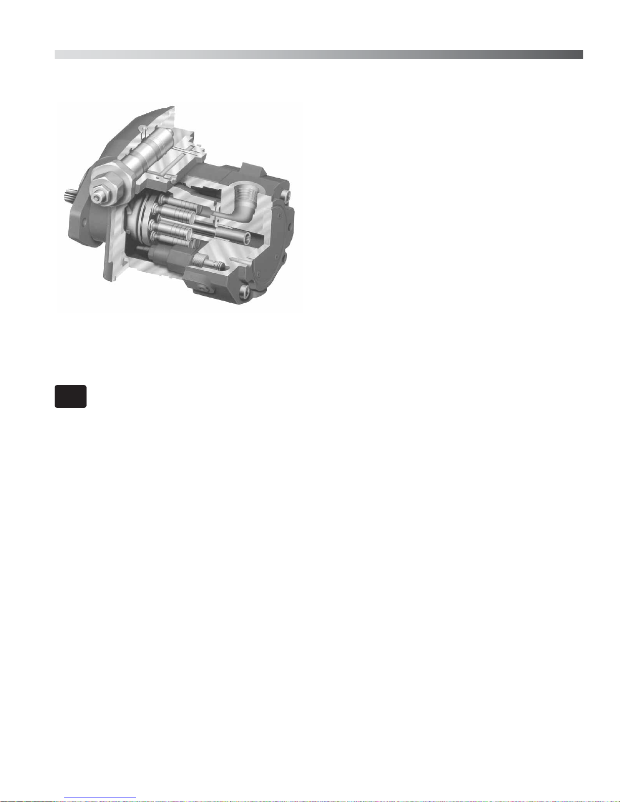
PRINCIPLE OF OPERATION
OILG0020
Figure 2. Cut-a-way of a Typical “PVM”
Pump (01010)
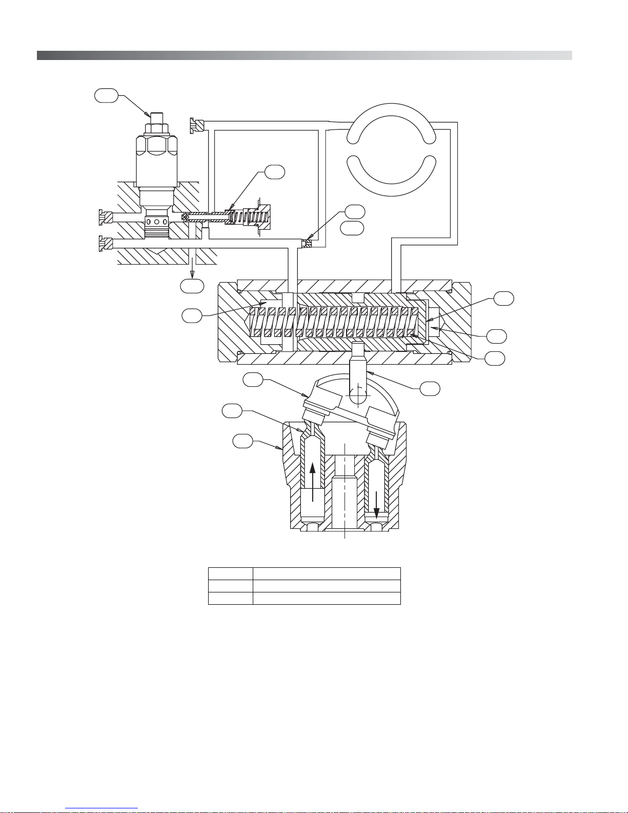
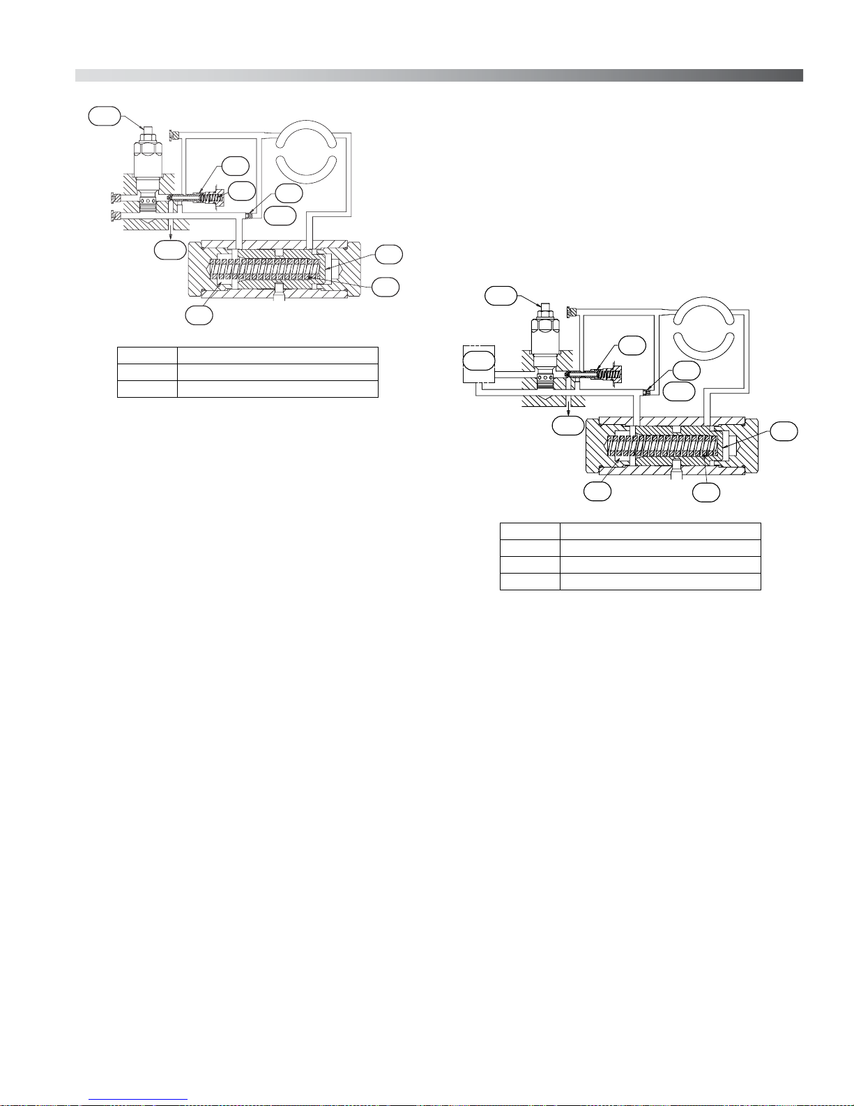
Full Stroke Operation - Figure 3
NOTE
The control piston (19) positions the control pin
(31) and pump swashblock (29) so the pump will
deliver maximum volume to raise pressure in the
system.
Raising Pressure
Pump delivery (and resultant pressure) is fed to
both sides of the control piston (19). Pressure to
the unloading side (C) of the control piston is
direct. Pressure to the bias side (D) of the control
piston is maintained by the respective control.
Numbers in parentheses represent item
number in parts list and drawings.
The areas on either end of the control piston are
the same and the pressure acting on either end is
the same. The resultant hydraulic forces on the
ends of the control piston cancel each other out
(the control piston is balanced), and the force of the
control piston spring (20) controls the control piston
position (19).
Rotating the driveshaft turns the splined cylinder
(38), which contains the pumping pistons (39).
When the cylinder rotates, the pistons move in and
out within their bores as the shoes ride against the
angled swashblock (29).
As the cylinder rotates, the individual piston bores
are connected, alternately, to the crescent shaped
upper (P) and lower (S) in the valve plate. While
connected to the lower side (suction) S, each
piston moves outward OUT, drawing fluid from S
into the piston bore until its outermost stroke is
reached. At this point, the piston bore passes from
the lower crescent S to the upper crescent P.
While rotating across the upper crescent port, each
piston moves across the angled swashblock face
and then each piston is forced inward IN. Each
piston then displaces fluid through the upper
crescent to P until its inner most stroke is reached.
At this point, the piston bore passes from the upper
to the lower crescent again and the cycle is
repeated.
The angle of the swashblock determines the length
of the piston stroke, (the difference between
outermost and innermost position) which
determines the amount of delivery from the pump.
If the stroke angle is one-half of the stroke, the
piston stroke is one-half and the pump delivery is
one-half.
Note that the flow through the PC control cartridge
(3-1) is blocked.
Bulletin 947070-B THE OILGEAR COMPANY 11
3-1
HP
RP
3-3
D
LS
P
54
S
68
3-2
19
C
20
29
39
38
OUT
(3-1) PC Control Cartridge
(3-2) Stability Orifice
(3-3) Into Case
Figure 3. Full Stroke Operation
31
IN
OILG0119
12 THE OILGEAR COMPANY Bulletin 947070-B
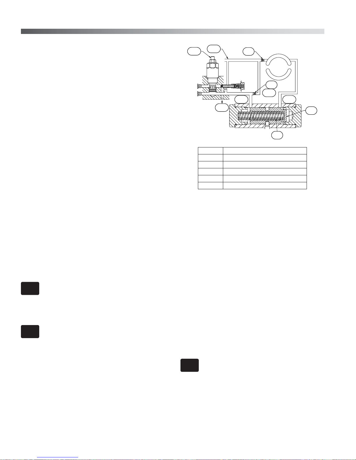
4-1
Relatively small variations in system flow
LS
P
requirements can be accommodated for in the
mentioned operational mode. When pump outlet
54
HP
RP
4-3
53
S
68
4-2
19
pressure decreases below the preset pressure
setting of the PC Control Cartridge, the PC Control
Cartridge closes. The sequence spool spring (53)
repositions the sequence spool to open the flow
path. This provides for an unobstructed flow path to
the bias side of the control piston so the pump will
be responsive to increased system flow demand.
20
D
(4-1) PC Control Cartridge
(4-2) Stability Orifice
(4-3) Into Case
OILG0115
Figure 4. Pressure Compensating
Pressure Compensating - Figure 4
When pump outlet pressure reaches the preset
pressure setting of the PC Control Cartridge, bias
pressure D (pressure on the spring side of the
control piston) is relieved by the PC Control
Cartridge. Exhaust flow from the PC Control
Cartridge is ported to the pump case via the
sequence spool (54). The resulting pressure drop
across the sequence spool due to the exhaust flow
moves the spool to block the flow path. All flow to
the PC Control Cartridge is now provided via the
stability orifice OP2 (68).
Blocking the flow path and requiring all control flow
to pass through OP2 minimizes case drain leakage
and provides a means of stability adjustment for a
wide range of system requirements. The decrease
in bias pressure results in a pressure differential
across the control piston (19). The control piston is
no longer balanced and the pressure on the
unloading side of the control piston forces the
control piston to compress the control piston spring
(20). The control piston moves the control pin and
shifts the swashblock to a position that provides
less flow output from the pump. Flow output from
the pump is then controlled to maintain the preset
pressure setting of the PC Control Cartridge. When
the outlet port of the pump is blocked, the
swashblock is positioned so the pump delivers just
enough volume to provide for internal losses and
required control flow.
5-1
5-2
HP
RP
(5-1) PC Control Cartridge
(5-2) Remote Pressure Control Valve
(5-3) Stability Orifice
(5-4) Into Case
5-4
LS
54
D
5-3
68
20
P
S
19
OILG0116
Figure 5. Remote Pressure Compensating
Remote Pressure Compensating - Figure 5
Principal of operation for remote pressure
compensating is the same as the integral pressure
compensating except another pressure control
valve is placed in parallel with the PC Control
Cartridge.
The supply port of the remote pressure control
valve needs to be ported to the RP port on the
valve plate (43). The exhaust from the remote
pressure control valve needs to be ported to the
HP port on the valve plate. When pump outlet
pressure reaches the preset pressure setting of the
remote control valve, bias pressure D [pressure on
the spring side of the control piston (19)] is relieved
by the remote control valve. Exhaust flow from the
remote control valve is ported to the pump case via
the sequence spool (54). The resulting pressure
drop across the sequence spool due to the exhaust
flow mov es th e spool to block the flow path. All flow
to the remote control valve is now provided via the
stability orifice OP2 (68). Blocking the flow path
and requiring all control flow to pass through OP2
Bulletin 947070-B THE OILGEAR COMPANY 13
minimizes case drain leakage and provides a
means of stability adjustment for a wide range of
system requirements.
6-1
6-6
69
LS
P
The decrease in bias pressure results in a pressure
differential across the control piston (19). The
control piston is no longer balanced and the
pressure on the unloading side of the control piston
forces the control piston to compress the control
piston spring (20). The control piston moves the
control pin and shifts the swashblock to a position
that provides less flow output from the pump. Flow
output from the pump is then controlled to maintain
the preset pressure setting of the remote pressure
control valve. When the outlet port of the pump is
blocked, the swashblock is positioned so the pump
delivers just enough volume to provide for internal
losses and required control flow.
Relatively small variations in system flow
requirements can be accommodated for in the
mentioned operational mode, but, when pump
outlet pressure decreases below the preset
pressure setting of the remote control valve, the
remote control valve closes. The sequence spool
spring (53) repositions the sequence spool to open
the flow path. This provides for an unobstructed
flow path to the bias side of the control piston so
the pump will be responsive to increased system
flow demand. If the setting of the remote pressure
control valve exceeds the setting of the PC Control
Cartridge, the pump will control to the setting of the
PC Control Cartridge.
NOTE
Failure to port the exhaust of the remote
pressure control valve to the HP port will
result in significantly higher case drain
leakage.
6-2
68
20
S
19
OILG0118
HP
RP
6-5
(6-1) PC Control Cartridge
(6-2) Stability Orifice
(6-3) Bias D
(6-4) Outlet C
(6-5) Into Case
(6-6) Load Sense Port
Figure 6. Standard Load Sensing with Pressure
Compensating Override
6-3 6-4
Standard Load Sensing with Pressure
Compensator Override - Figure 6
The parts configuration for the Standard Load
Sense control is similar to the Pressure
Compensator control except for the installation of a
plug. All other components are unchanged. A 1/16
inch pipe plug is supplied with all new pumps. The
plug is installed in a blind hole next to the LS port
for all pumps originally shipped as a Pressure
Compensator control or Adjustable Load Sense
control. The plug (69) is already installed in the
correct location (and the blind hole is empty), if the
pump was originally shipped as a Standard Load
Sense.
NOTE
The RP lines of multiple pumps cannot be
tied together for unloading or controlling
with a common remote pressure control
valve. Each pump requires a dedicated
valve.
14 THE OILGEAR COMPANY Bulletin 947070-B
To convert to a Standard Load Sense from a
Pressure Compensator control, install the pipe plug
(69) deep into the LS port of the valve plate as
shown in Figure 6.
NOTE
The pipe plug threads start approximately
1.7 inch (0.043 mm) from the port spotface.
Standard Load Sense control requires the load
sense line (pressure signal from downstream of an
orifice or flow control valve) be attached at the LS
port on the valve plate assembly. Load sense
pressure is ported via the sequence spool and
stability orifice to the bias side of the control piston
(19). The pressure differential across the system
flow control is therefore equal to the pressure
differential across the control piston; when the
pressure differential reaches the non-adjustable
preload force of the control spring, the control
piston moves toward the neutral position. The
control piston moves the control pin and shifts the
swashblock to a position that reduces pump
delivery to maintain a constant, preset pressure
differential across the flow control v alv e . The preset
pressure differential is 150 to 210 psi (10,3 to 14,5
bar). If the pressure differential across the flow
control valve is decreased, t he control piston spring
(20) moves the control piston in the full stroke
direction until pump delivery is increased
sufficiently to reach the preset load sense
differential pressure. When the pump outlet is
blocked and the load sense pressure is allowed to
go to drain pressure, the swash is positioned so
that the pump delivers just enough volume to
provide for internal losses and required control flow
at a standby pressure equal to the preset pressure
differential of 150 to 210 psi (10,3 to 14,5 bar).
The pressure compensating function will override
the load sense control and, if necessary, further
reduce pump delivery when the load sense
pressure reaches the preset pressure of the PC
Control Cartridge.
7-1
7-4
7-5
Figure 7. Adjustable Load Sensing with Pressure
LS
HP
RP
(7-1) PC Control Cartridge
(7-2) Stability Orifice
(7-3) Into Case
(7-4) Load Sense Port
(7-5) Adjustable Load Sense Cartridge
LS
54
53
7-3
D
Compensating Override
68
7-2
20
P
S
19
OILG0117
Adjustable Load Sensing w/ Pressure
Compensator Override - Figure 7
The Adjustable Load Sense control functions
similar to the Standard Load Sense control except it
is adjustable from 150 to 600 psi (10,3 to 41,4 bar).
The Adjustable Load Sense Cartridge is located
adjacent to the PC Control Cartridge on the valve
plate. The Adjustable Load Sense does not require
the installation of the 1/16 inch pipe plug in the
standard load sense port as previously described.
The standard load sense port should be plugged
with an SAE #4 plug. Adjustable Load Sense
control requires the load sense line [pressure
signal from downstream of an orifice or flow control
valve] be attached to the end of the Adjustable
Load Sense Cartridge.
When load sense pressure differential reaches the
preset pressure setting of the Adjustable Load
Sense Cartridge, bias pressure D [pressure on the
spring side of the control piston (19)] is relieved by
the Adjustable Load Sense Cartridge. Exhaust flow
from the Adjustable Load Sense Cartridge is
ported to the pump case via the sequence spool.
The resulting pressure drop across the sequence
spool (54) due to the exhaust flow moves the spool
to block the flow path. All flow to the Adjustable
Load Sense Cartridge is now provided via the
stability orifice OP2 (68). Blocking the flow path
and requiring all control flow to pass through OP2
minimizes case drain leakage and provides a
means of stability adjustment for a wide range of
system requirements.
The decrease in bias pressure results in a pressure
differential across the control piston (19). The
control piston is no longer balanced and the
pressure on the unloading side of the control piston
forces the control piston to compress the control
piston spring (20). The control piston moves the
control pin and shifts the swashblock to a position
that provides less flow output from the pump. Flow
output from the pump is then controlled to maintain
the preset pressure differential setting of the
Adjustable Load Sense Cartridge. When the outlet
port of the pump is blocked, the swashblock is
positioned so the pump delivers just enough
volume to provide for internal losses and required
control flow at a standby pressure equal to the
differential pressure setting of the Adjustable Load
Sense Cartridge.
Bulletin 947070-B THE OILGEAR COMPANY 15

Relatively small variations in system flow
requirements can be accommodated for in the
mentioned operational mode, but, when pump
outlet pressure decreases below the preset
differential pressure setting of the Adjustable Load
Sensing Cartridge, the Adjustable Load Sensing
Cartridge closes. The sequence spool spring (53)
repositions the sequence spool to open up the flow
path. This provides for an unobstructed flo w path to
the bias side of the control piston so the pump will
be responsive to increased system flow demand.
The pressure compensating function will override
the load sense control and, if necessary, further
reduce pump delivery when the load sense
pressure reaches the preset pressure of the PC
Control Cartridge.
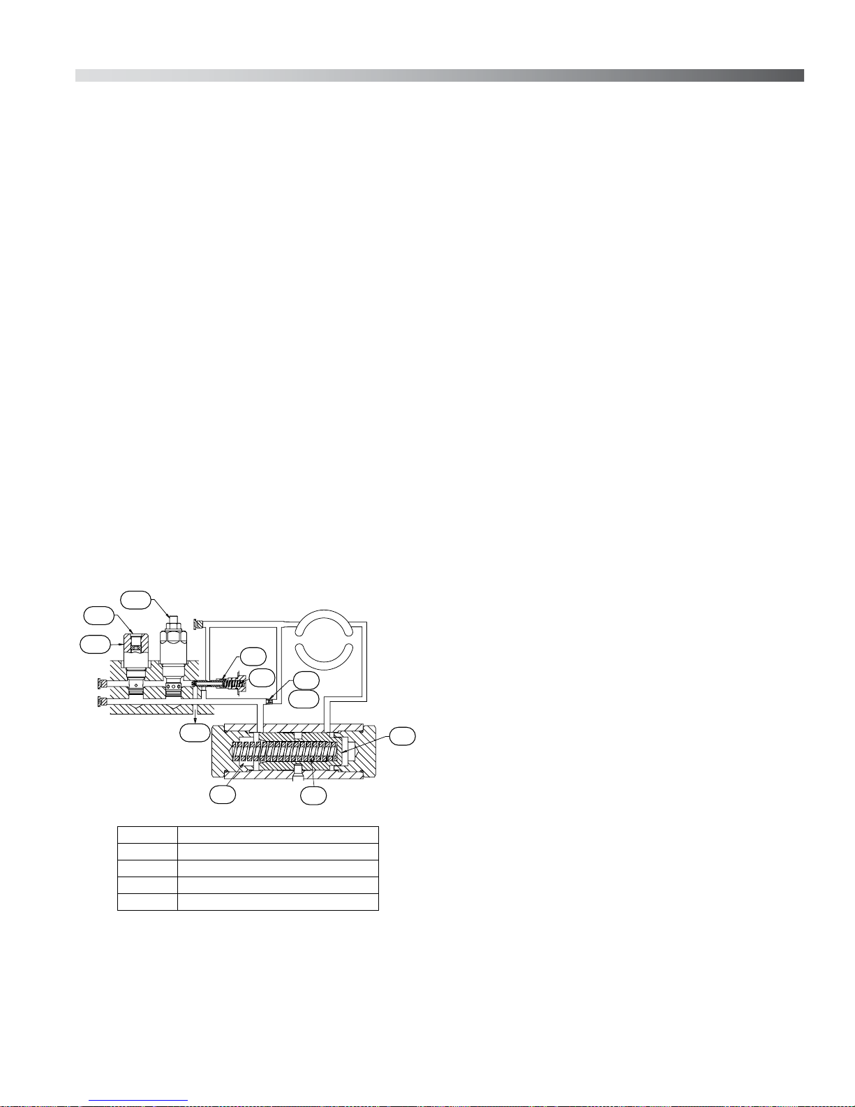
Electronic Proportional Pressure Compensator
with Override - Figure 8
The Electronic Proportional Pressure Compensator
functions the same as the Pressure Compensating
Control (refer to Figure 4) except the PC Control
Cartridge is electrically controlled. An electrical
signal is used to proportionally increase or
decrease the pressure compensator setting with
increasing current. A manually adjustable PC
Override Valve enables the user to set the
maximum desired pressure compensator setting.
NOTE
An Adjustable Load Sense control is also
available with a bleed-off feature. This
cartridge internally vents load sensing
pressure to case via an orifice in the
cartridge and the sequence spool when the
control is not active or the system is
shutdown.
8-2
8-1
LS
HP
RP
LS
8-8
8-9
8-7
8-3
P
S
8-4
8-5
8-6
(8-1) PC Override Cartridge
(8-2) Electronic Proportional Control Cartridge
(8-3) Sequence Spool
(8-4) Stability Orifice (OP2)
(8-5) Control Piston
(8-6) Control Pin
(8-7) Cylinder Barrel
(8-8) Piston
(8-9) Swashblock
(8-10) Into Case
Figure 8. Electronic Proportional Pressure
16 THE OILGEAR COMPANY Bulletin 947070-B
OILG0170
Compensator with Override

TESTING AND ADJUSTING
WARNING
!
Shut the pump OFF and release pressure
from the system before disassembling
components. Failure to comply with these
instructions could result in personal injury
or death. Blocking the pressure line
between the pump and the system (or
pump) high pressure relief valve will result
in damage and could result in serious
personal injury.
PISTON PUMP
To check for a worn piston pump, make a leak
measurement test from the case drain while the
pump is under pressure. After the unit is warm,
either install a flow meter in the drain line or have
the flow from the drain line directed into a large
container or reservoir. The pump case must remain
full of fluid during this test.
CAUTION
DO NOT run a pump on stroke against a
blocked output unless it is protected by a
high pressure relief valve and then run no
longer than necessary to check slip. Limit
discharge to prevent dropping reservoir
fluid below low level.
With an accurate high pressure gauge in the
pressure line, start the pump and stall (or block)
output device to raise system pressure to
maximum (as set by system relief valve). Read the
measurement on the flow meter or time and
measure the case drain flow used to fill a known
size container and calculate the flow rate in terms
of cubic inches per minute (cipm). The leakage
should conform to Table 5.
NOTE
Additional leakage indicates wear, but
does not become critical until it impairs
performance.
DISASSEMBLY
Refer to
pump.
NOTE
DO NOT attempt to remove or install any
components or assembly while the pump
and system is running. Always stop the
pump, shut OFF the power and release
pressure from the system before servicing
or testing. Be sure provisions have been
made so the case drain line can be
disconnected from the unit without
causing the line to drain (siphon) the
reservoir.
1. Disconnect case drain line(s).
2. Drain pump case. If drain pump case plugs are
Figures 9 through 15
The cleanliness of working on this pump or
the hydraulic system is extremely important
to the safety and reliability of the pump and
the system.
When disassembling or assembling the
pump, choose a clean, dry, dust and sand
free area where no traces of abrasive
particles are in the air which can damage
the pump and system. DO NOT work near
welding, sandblasting, grinding benches or
similar conditions.
Always make sure the fittings are clean on
the outside before removing them from
their connections. Make sure they are
capped and plugged when removed. Place
them on a clean surface and in a clean rag
or container until they are reinstalled.
When cleaning parts which have been
disassembled, it is important to use
CLEAN cleaning solvents and parts are
allowed to dry. All tools and gauges should
be clean prior to working with the system
and use new, CLEAN lint free rags to
handle and dry parts.
WARNING
!
inaccessible, it may be necessary to remove
the pump from the mounting and drive motor
before draining it.
for your series of
Bulletin 947070-B THE OILGEAR COMPANY 17
(continued)

DISASSEMBLY (Continued)
CAUTION
WARNING
!
Seek assistance from others and use of a
hoist and/or proper lifting techniques to
prevent personal injury.
NOTE
3. After removing the pump from the mounting
NOTE
VALVE PLATE GROUP
If another pump is coupled with a thru-shaft pump
or other device coupled to the rear of the pump, it
will be necessary to remove that unit and O-ring
(59). If thru-shaft convertible cover (63) is used,
remove the socket head cap screws (64) and
O-ring (62). Also remove screw (61) and thru-shaft
coupling spacer (60).
Tag similar par ts (particularly screws, plugs
and O-rings) during disassembly to make
sure they don't become confused with
similar parts and to ensure they will be
returned to their original location. Do not
remove (locator) roll pins unless they are
deformed or need to be replaced.
and before disassembly, cap or plug all ports
and clean the outside of unit thoroughly to
prevent dust from entering the system.
Depending on what part or par ts are to be
inspected, it may not be necessary to
completely take apart all assemblies.
Do not damage the faces of the port plate
and the matching faces of both the valve
plate and cylinder barrel.
1. Block the unit on bench with driveshaft
horizontal.
2. Remove valve plate assembly (45) by removing
four socket head cap screws (50 and 56) and
the valve plate assembly. When used, shaft
coupling (57) with retaining rings (58), if used,
will come with valve plate assembly. The port
plate (43) is located on the valve plate
assembly by a dowel pin. Remove the port
plate from the valve plate assembly.
The control sequence valve can be removed, if
necessary by:
(A) Removing the sequence valve spool plug
(51) with the O-ring (52).
(B) Withdrawing sequence valve spool spring
(53) and sequence valve spool (54).
The PC control cartridge (55) can also be
unscrewed from the valve plate if necessary. The
rear shaft bearing (67 or 77) is pressed into the
valve plate.
18 THE OILGEAR COMPANY Bulletin 947070-B
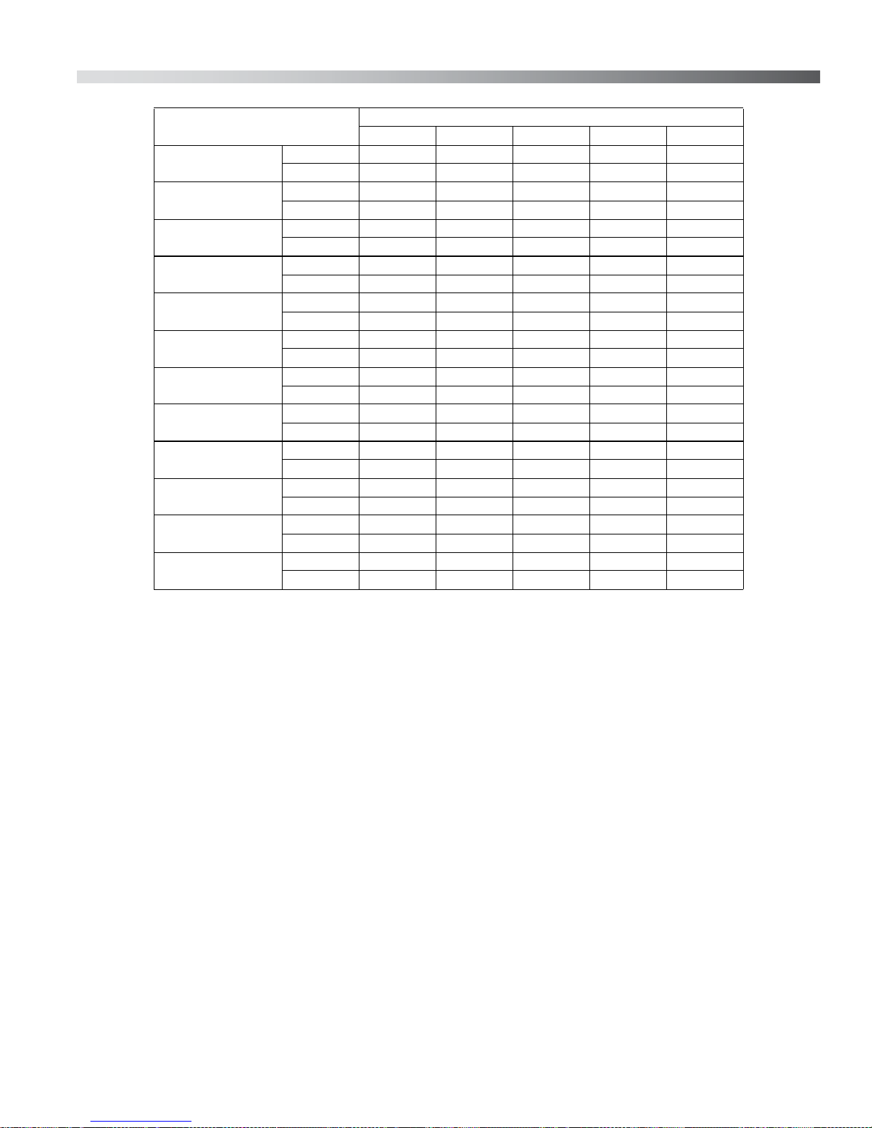
Frame Unit - Size
SAE “A” PVM-011
SAE “A” PVM-014
SAE “A” PVM-022
SAE “B” PVM-025
SAE “B” PVM-034
SAE “B” PVM-046
SAE “B” PVM-065
SAE “B” PVM-075
SAE “C” PVM-064
SAE “C” PVM-076
SAE “C” PVM-098
SAE “C” PVM-130
Case Slip at Full Stroke and Indicated Pressure
500 psi 1000 psi 2000 psi 3000 psi 3750 psi
cipm 25.0 40.0 75.0 110.0 160.0
lpm0,410,661,23 1,80 2,62
cipm 35.0 50.0 80.0 120.0 170.0
lpm0,570,821,31 1,97 2,79
cipm 55.0 90.0 145.0 210.0 300.0
lpm0,901,472,38 3,44 4,92
cipm 75.0 115.0 185.0 270.0 360.0
lpm 1,23 1,88 3,03 4,42 5,90
cipm 70.0 105.0 175.0 255.0 340.0
lpm 1,15 1,72 2,87 4,18 5,57
cipm 70.0 105.0 180.0 280.0 365.0
lpm 1,15 1,72 2,95 4,59 5,98
cipm 95.0 135.0 205.0 300.0 400.0
lpm 1,56 2,21 3,36 4,92 6,55
cipm 140.0 190.0 290.0 450.0 650.0
lpm 2,29 3,11 4,75 7,37 10,65
cipm 90.0 135.0 230.0 345.0 460.0
lpm 1,47 2,21 3,77 5,65 7,54
cipm 90.0 145.0 245.0 390.0 580.0
lpm 1,47 2,384,016,399,50
cipm 125.0 180.0 280.0 560.0 860.0
lpm2,082,954,599,1814,09
cipm 135.0 210.0 370.0 580.0 810.0
lpm 2,21 3,44 6,06 9,50 13,27
Table 5. NOMINAL CASE SLIP versus High Pressure at 1800 rpm
[All data is for ISO 46 mineral-based oil at 125°F (160 SSU)]
Bulletin 947070-B THE OILGEAR COMPANY 19
ROTATING GROUP
WARNING
!
The rotating group may be heavy. Be
careful not to damage cylinder wear
surface which mates against the valve
plate, bearing diameters or piston shoes.
Use proper lifting techniques and
assistance from others to prevent
personal injury.
-011/-014/-022
5. Remove cylinder barrel retaining ring (37) and
pull the hydrodynamic cylinder bearing (35) and
roll pins, if necessary, from the housing.
-025/-034/-046/-064/-065/-075/
-076/-098/-130
5. Remove the hydro-bearing retaining ring (37).
1. Remove O-rings (13 and 14) from the pump
housing (1). Do not remov e roll pins (12) unless
they are damaged.
2. Remove the rotating group by turning the
driveshaft (21) slowly, while pulling the cylinder
barrel (38) from the housing.
3. Identify (number) each pump piston shoe
assembly (39) and its respective bore in the
cylinder barrel (38) and shoe retainer plate (40)
for easy reassembly.
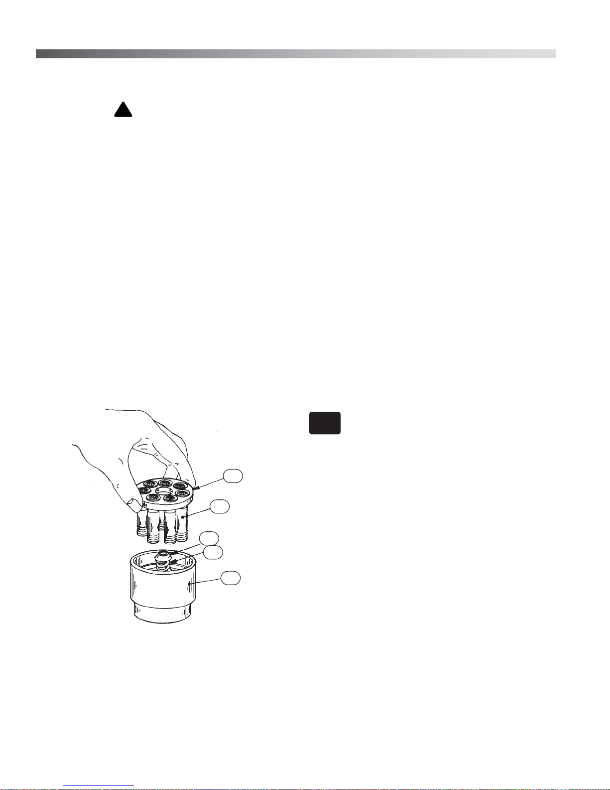
4. See Figure 9. Lift out shoe retainer (40) with
pistons (39) and remove the fulcrum ball (41)
and shoe retainer spring (42).
40
39
41
42
38
6. Remove socket head screw (36) and lock
washer (5).
7. Pull hydrodynamic cylinder bearing (35) from
housing.
DRIVESHAFT GROUP
1. Remove the drive key (22 or 23), if used and
the driveshaft bearing retainer ring (28).
2. Grasp outboard end of driveshaft (21) and pull
it out of the pump housing.
3. Remove shaft seal retainer (25). Remove
driveshaft seal (24) from housing ONLY if
necessary.
NOTE
If the seal is removed it can not be reused.
It must be replaced.
SWASHBLOCK GROUP
1. Remove the socket head cap screws (34), the
housing cover (33) and O-ring (32).
2. Reach into the housing through the opening
and pull out the swashblock (29), along with
control pin (31).
The saddle bearing (30) is seated in the housing by
an integral pintle that engages a hole in the
housing.
Figure 9. Rotating Group Disassembly
20 THE OILGEAR COMPANY Bulletin 947070-B
OILG0023
3. Pull the saddle bearing (30) back (parallel to
driveshaft axis) until the pintle disengages from
the housing, then pull the saddle bearing out in
the same manner the swashblock was
removed.
 Loading...