

OilGear F1U, PVG 065, PVG 048, PVG 075 Service Manual
Bulletin 947023
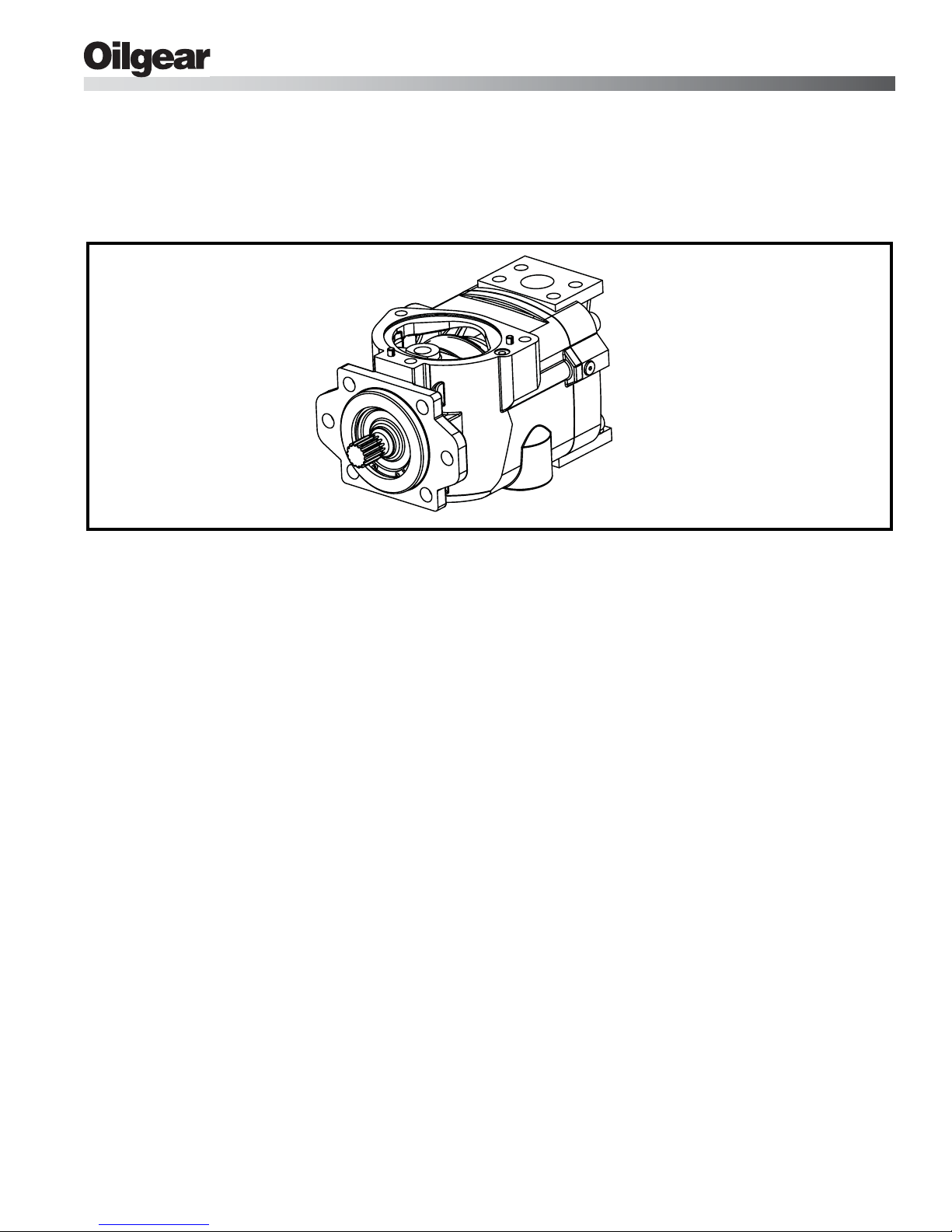
OILGEAR TYPE “PVG” PUMPS -
-048/-065/-075 (SERIES F1U)
SERVICE INSTRUCTIONS
OILG0457
Figure 1. Typical Oilgear “PVG” Open Loop Pump
PURPOSE OF INSTRUCTIONS
These instructions will simplify the installation,
operation, maintenance and troubleshooting of
Oilgear type “PVG” pumps.
REFERENCE MATERIAL
Fluid Recommendations .....................................................................................Bulletin 90000
Contamination Evaluation Guide.........................................................................Bulletin 90004
Filtration Recommendations ...............................................................................Bulletin 90007
Piping Information ...............................................................................................Bulletin 90011
Installation of Vertically Mounted Axial Piston Units ...........................................Bulletin 90014
PVG Open Loop Pumps, Sales........................................................................ Bulletin 47019-I
Pump Control Instructions, Series F1U
“P-1NN” Single Pressure Compensator ............................................................Bulletin 947651
“P-1NN/F” Single Pressure Compensator w/Load Sense.................................Bulletin 947652
“P-1NN/H” Single Pressure Compensator w/H.P. Limiter
“P-1NN/G” Horsepower Limiter w/Load Sense .................................................Bulletin 947654
“P-2” Dual Pressure Compensator....................................................................Bulletin 947655
“P-C” Single Pressure - Soft Start.....................................................................Bulletin 947656
“P-A” or “P-B” Electronic Pressure Compensator .......................Bulletins 947556 and 947657
“P-CNN/H” Single Pressure - Soft Start w/H.P. Limiter ...............Bulletins 947558 and 947658
“P-2NN/H” Dual Pressure Compensator w/H.P. Limiter ..............Bulletins 947559 and 947659
“V-S25” Electro Hydraulic Servo Valve..............................................................Bulletin 947560
“V-M20” Electro Hydraulic Servo Valve .............................................................Bulletin 947561
Become familiar with the construction, principle of
operation and characteristics of your pump to help
you attain satisfactory performance, reduce shutdown and increase the pump's service life. Some
pumps have been modified from those described in
this bulletin and other changes may be made
without notice.
....................................Bulletin 947653
Bulletin 947023 THE OILGEAR COMPANY 1
November 2009
THE OILGEAR COMPANY
2300 South 51st Street
Milwaukee, Wisconsin 53219
www.oilgear.com
Bulletin 947023
Safety First
Read and understand this entire instruction sheet
before repairing, or adjusting your Oilgear product.
Those who use and maintain this equipment must
be thoroughly trained and familiar with the product.
If incorrectly used or maintained, this product and
its equipment can cause severe injury.
SAFETY SYMBOLS
The following signal words are used in this
instruction sheet to identify areas of concern where
your safety may be involved. Carefully read the text
and observe any instructions provided to ensure
your safety.
DANGER
THIS SIGNAL WORD INDICATES AN
IMMINENTLY HAZARDOUS SITUATION
WHICH, IF NOT AVOIDED, WILL RESULT IN
DEATH OR SERIOUS INJURY.
WARNING
!
This signal word indicates a potentially
hazardous situation which, if not avoided,
could result in death or serious injury.
CAUTION
This signal word indicates that a potentially
hazardous situation exists which, if not
avoided, may result in damage to
equipment or minor personal injury.
NOTE
While not directly relevant to the topic being
discussed, the NOTE is used to emphasize
information provided, or provide additional
information which may be of benefit.
WARNING
!
This service information is designed for
the maintenance of your Oilgear product.
It contains the information on the correct
procedures determined by Oilgear for the
safe manner of servicing. Always keep
this instruction sheet in a location where it
is readily available for the persons who
use and maintain the product. Additional
copies of this instruction sheet are
available through the Oilgear Company.
Or visit our website: www.oilgear.com.
Please contact us if you have any
questions regarding the information in
this instruction bulletin.
NOTE
The cleanliness of working on this pump or
the hydraulic system is extremely
important to the safety and reliability of the
pump and the system. Always make sure
the fittings are clean on the outside before
removing them from their connections, are
capped and plugged when removed and
placed in a clean rag or container until they
are reinstalled.
WARNING
!
Some service operations may require
special tools or equipment. If you require
information on these items, please contact
Oilgear before attempting these repairs
and service operations.
WARNING
!
Read, understand, and follow the safety
guidelines, dangers, and warnings
contained in this instruction sheet to
promote reliable operation and prevent
serious personal injury.
WARNING
!
DO NOT attempt to service this machinery
in an environment where safety regulations
are not established and in place.
WARNING
!
DO NOT operate the hydraulic system if a
leak is present. Serious injury may result.
WARNING
!
Hydraulic systems operate under very high
pressure. Hydraulic fluid escaping from a
pressurized system can penetrate
unprotected body tissue. DO NOT inspect
for hydraulic leaks with bare hands or other
exposed body parts. As a minimum, wear
leather gloves prior to inspecting for leaks
and use cardboard or wood. If leaks are
present, relieve pressure and allow system
to cool prior to servicing. If injured by
escaping hydraulic oil, contact a physician
immediately. Serious complications may
arise if not treated immediately. If you have
questions regarding inspecting for
hydraulic leaks, please contact Oilgear
prior to servicing.
2 THE OILGEAR COMPANY Bulletin 947023
© 2009 THE OILGEAR COMPANY - ALL RIGHTS RESERVED
Safety First
WARNING
!
Hydraulic hoses and tubing must be
inspected on a daily basis for leaks, cuts,
abrasions, damage and improper
clearance along any mounting frame for
hidden damage before the unit is put into
service. Replace damaged hoses or hoses
you suspect are damaged before the
system is returned to service! Hoses must
be replaced every two years. Failure to
properly inspect and maintain the system
may result in serious injury.
WARNING
!
Hydraulic systems are hot. DO NOT
TOUCH! Serious personal injury may
result from hot oil. When you have
completed working on the hydraulic
system, thoroughly clean any spilled oil
from the equipment. Do not spill any
hydraulic fluids on the ground. Clean any
hydraulic fluids from your skin as soon as
you have completed maintenance and
repairs. Dispose of used oil and system
filters as required by law.
WARNING
!
Hydraulic cylinders can be holding a
function in a certain position when the
pump is OFF. An example of this is a
function being held in the lift or partial lift
position by the cylinders. If a hydraulic
line is removed or the hydraulic circuits or
controls are being worked on, gravity may
allow the function being held in position to
drop. All workers and personnel must
remain clear of these areas when working
on or operating the hydraulic system.
Block and secure all devices and
functions which apply before beginning
work or operation. Failure to comply with
this can result in serious injury or death.
WARNING
!
Any hydraulic pipe which is replaced must
conform to SAE J1065 specifications. If
incorrect hydraulic pipe is installed, the
hydraulic system may fail, causing
serious injury. Damaged or leaking
fittings, pipes or hoses must be replaced
before the system is returned to service.
WARNING
!
Use correct hoses, fittings, and adapters
with the correct SAE rating when
replacing hoses to prevent possible
serious injury. Always replace hoses,
fittings, and adapters with replacements
that have a proper, suitable, working
pressure rating. Replacement hoses must
be of the correct length and must comply
with the hose manufacturer’s and
Oilgear’s installation guidelines and
recommendations.
WARNING
!
Hydraulic hoses have the SAE ratings
marked on the hose to assist you in
selecting the correct hose. The same
manufacturer must supply any replacement
hydraulic hoses and fitting assemblies. As
an example: Brand “X” hose and brand “Y”
fitting will not normally be compatible. No
“Twist” is allowed in the hydraulic hoses.
“Twist” may result in premature hose
failure. This can cause serious injury.
Please contact Oilgear for assistance when
required.
WARNING
!
DO NOT heat hydraulic pipe. The carbon
content of this steel tube is such that if
heated for bending, and either water or air
quenched, the pipe may lose its ductility
and thereby be subject to failure under
high pressure conditions. Serious injury
can result. Damaged or leaking pipes must
be replaced before the system is returned
to service. Please contact Oilgear if you
require assistance or have questions.
WARNING
!
All hydraulic pressure must be relieved
from the hydraulic system prior to removing
any components from the system. To
relieve the hydraulic pressure from the
hydraulic system, turn off the motor and
operate the control panel with the key in the
ON position. Failure to comply can result in
serious injury. If you have any questions
concerning relieving the hydraulic pressure
from the system, please contact Oilgear.
Bulletin 947023 THE OILGEAR COMPANY 3
Safety First
WARNING
!
Hydraulic components can be heavy. Use
caution while lifting these components.
Serious personal injury can be avoided
with proper handling of the components.
WARNING
!
Please contact Oilgear if you require
assistance, when performing hydraulic
test procedures, use the proper hydraulic
gauges. Installing an incorrect test gauge
could result in serious injury if the gauge
fails. Use properly rated hydraulic hoses
to allow the test gauge to be read away
from moving parts and functions.
WARNING
!
Increasing hydraulic pressure beyond the
recommendations may result in serious
damage to the pump and system or
serious personal injury and may void the
Oilgear Warranty. If you have questions
concerning hydraulic pressures or testing
procedures, please contact Oilgear before
attempting the test procedures or making
adjustments.
WARNING
!
Any Oilgear pump safety decals must be
replaced anytime they are damaged,
missing, or cannot be read clearly. Failure
to have proper decals in place can result
in serious injury or death. (If you require
safety decals, please contact Oilgear for
replacement safety decals, at no charge.)
WARNING
!
Be sure everyone is clear of the area
around the hydraulic system before
operating after servicing. Remain attentive
at all times when operating to check your
work until you are completely sure it is
safe to return to service. Failure to heed
this warning may result in serious
personal injury or death.
WARNING
!
Wear the proper protective clothing when
operating, servicing or maintaining the
hydraulic system or the Oilgear pump. Wear
the correct protective gear, safety glasses,
gloves, and safety shoes. Serious injury
can result without proper protective gear.
WARNING
!
An Oilgear pump must not be modified in
any way without authorization from
Oilgear. Modifications may not comply
with safety standards, including ANSI
safety standards, and may result in
serious personal injury. Please contact
Oilgear if you require assistance.
WARNING
!
DO NOT enter under hydraulic supported
equipment unless they are fully supported
or blocked. Failure to follow this procedure
can result in serious injury or death.
WARNING
!
Make sure to keep hands and feet and
other parts of your body clear of revolving
or moving parts. Failure to comply can
cause serious injury.
WARNING
!
DO NOT wear watches, rings, or jewelry
while working with electrical and
mechanical equipment. These items can
be hazardous and can cause serious and
painful injuries if they come into contact
with electrical wires, moving parts, or
hydraulic equipment.
4 THE OILGEAR COMPANY Bulletin 947023

Service Instructions
PREPARATION AND
INSTALLATION
MOUNTING
Pump Without Reservoir - The pump can be
mounted in any position. But, the recommended
mounting position is with the drive shaft on a
horizontal plane and the case drain port 1 on the
top side. Secure the pump to a rigid mounting
surface. Refer to the referenced Oilgear Piping
Information Bulletin 90011.
Pump With Reservoir - These pumps are usually
fully piped and equipped. It may be necessary to
connect to a super-charge circuit when used.
Mount reservoir on level foundation with the
reservoir bottom at least six inches above floor
level to facilitate fluid changes.
PIPING AND FITTINGS
Refer to the referenced Oilgear Piping Information
Bulletin 90011 and individual circuit diagram before
connecting the pump to the system. Inlet velocity
must not exceed 5 fps (1,5 mps). Inlet should be
unrestricted and have a minimum of fittings.
NOTE
Arrange line from “case drain” so the case remains
full of fluid (non-siphoning). Case pressure must be
less than 25 psi (1,7 bar). For higher case
pressures, special shaft seals are required; contact
our Customer Service. Each drain line must be a
separate line, unrestricted, full sized and
connected directly to the reservoir below the lowest
fluid level. Make provisions for opening this line
without draining (siphoning) reservoir.
DO NOT use an inlet strainer.
WARNING
!
Running the pump in NEUTRAL position
(zero delivery) for extended periods
without a supercharge circuit can damage
the pump. The system and pump must be
protected against overloads by separate
high pressure relief valves. Install bleed
valve(s) at the highest point(s) in system.
POWER
Power is required in proportion to volume and
pressure used. Motor size recommendations for
specific applications can be obtained from The
Oilgear Company. Standard low starting torque
motors are suitable for most applications.
CAUTION
DO NOT start or stop unit under load
unless system is approved by Oilgear. It
may be necessary to provide delivery
bypass in some circuits.
DRIVE
Verify rotation direction plate on the pump's housing.
Clockwise pumps must be driven clockwise and
counterclockwise pumps must be driven
counterclockwise. Use direct drive coupling. Size
and install coupling per manufacturer's instructions.
CAUTION
DO NOT drive the coupling onto the pump
drive shaft. If it is too tight, it may be
necessary to heat coupling for installation.
Refer to manufacturer's instructions.
Misalignment of pump shaft to driver's shaft should
not exceed 0.005 inches (0,13 mm) Total Indicator
Readout (TIR) in any plane.
Bulletin 947023 THE OILGEAR COMPANY 5

FILTRATION
Keep the fluid clean at all times to ensure long life
from your hydraulic system. Refer to the referenced
Oilgear Filtration Recommendations bulletin 90007
and Oilgear Contamination Evaluation Guide
Bulletin 90004. Oilgear recommends use of a filter
in the pressure or return line. Replace filter
element(s) when the filter condition indicator
reaches change area at normal fluid temperature.
Drain and thoroughly clean filter case. Use
replacement element(s) of same beta 10 ratio
(normally a ratio of 4 with hydraulic oils).
FLUID COOLING
When the pump is operated continuously at the
rated pressure or frequently at peak load, auxiliary
cooling of the fluid may be necessary. Fluid
temperature should not exceed limits specified in
the referenced Oilgear Fluid Recommendations
Bulletin 90000.
With pump under “no load” or with pump control at
NEUTRAL:
4. Turn drive unit ON and OFF several times
before allowing pump to reach full speed. The
system can usually be filled by running the
pump and operating the control.
5. The fluid level in the reservoir should decrease.
Stop the pump. DO NOT allow the fluid level to
go beyond the “low level.” If the level reaches
“low level” mark, add fluid and repeat step.
NOTE
With differential (cylinder) systems, the fluid
must not be above “high level” when the
ram is retracted or below “low level” when
extended. Bleed air from the system by
loosening connections or opening petcocks
at the highest point in the system. Close
connections or petcocks tightly when solid
stream of fluid appears.
CONSTRUCTION
AIR BREATHER
On most installations, an air breather is mounted
on top of fluid reservoir. It is important for the
breather to be the adequate size to allow air flow in
and out of reservoir as fluid level changes. Keep
the breather case filled to the “fluid level” mark.
About once every six months, remove cover, wash
screen in solvent and allow screen to dry, clean
and refill case to level mark and install screen.
Refer to the manufacturer's recommendations.
FLUID, FILLING AND STARTING
RECOMMENDATIONS
Refer to instruction plate on the unit, reservoir,
machine and/or reference Fluid Recommendations
bulletin. Fire-resistant fluids and phosphate ester
fluids can be used in accordance with fluid
manufacturer's recommendations.
1. Pump all fluid into reservoir through a clean
(beta 10 ratio of 4 or more) filter. Fill reservoir
to, but not above, “high level” mark on the sight
gauge.
2. Remove case drain line and fill pump case
with hydraulic fluid.
3. Turn drive shaft a few times by hand with a
spanner wrench to make sure parts rotate.
Torque to turn drive shaft should be 9 to 24 ft•lb
(12 to 32 N•m).
See Figure 3.
1. A drive shaft (301) runs through the center line
of pump housing (001) and valve plate (401)
with the pump cylinder barrel (101) splined to it.
2. A bearing (306) supports the outboard end of
the drive shaft and a bushing supports the
inboard end. (The bushing is part of valve plate
assembly.)
3. The pump cylinder barrel is carried in a
polymerous (journal type) cylinder bearing
(202).
4. The valve plate (401) has two crescent shaped
ports.
5. The pumping piston/shoe assemblies (102) in
the cylinder barrel are held against a
swashblock (201) by a shoe retainer (104).
6. The shoe retainer is held in position by the
fulcrum ball (103) which is forced outward by
the shoe retainer spring (105).
7. The spring acts against the pump cylinder
barrel, forcing it against the valve plate while
also forcing the piston shoes against the
swashblock.
8. The semi-cylindrical shaped swashblock limits
the piston stroke and can be swiveled in arcshaped saddle bearings (204).
9. The swashblock is swiveled by a control
(included in referenced material). Refer to
PRINCIPLE OF OPERATION.
6 THE OILGEAR COMPANY Bulletin 947023
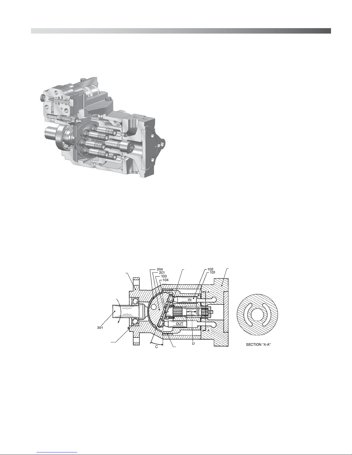
PRINCIPLE OF OPERATION
The illustrations show the pump driven clockwise
(right hand) from the top (plan) view.
Position B, Pump During Full Delivery from
PORT B - Figure 3
Rotating the drive shaft (301) clockwise turns the
splined cylinder, which contains the pumping
pistons (102). When the cylinder rotates, the
pistons move in and out within their bores as the
shoes ride against the angled (C) swashblock
(201).
As the cylinder rotates, the individual piston bores
are connected, alternately, to the crescent-shaped
upper (port A) and lower (port B) in the valve plate.
While connected to the upper side (suction) port A,
each piston moves outward (OUT), drawing fluid
from port A into the piston bore until its outermost
stroke (D) is reached. At this point, the piston bore
passes from the upper crescent port A to the lower
crescent port B.
OILG0363
Figure 2. Cut-a-way of a Typical “PVG”
Pump
001
306
While rotating across the lower crescent, each
piston moves across the angled swashblock face
and then each piston is forced inward (IN). Each
piston then displaces fluid through the lower
crescent to port B until its innermost stroke (D) is
reached. At this point, the piston bore passes from
the lower to the upper crescent again and the cycle
is repeated.
105
202
401
A
B
OIL_0001
Figure 3. Position B, Pump During Full Delivery from Port B
Bulletin 947023 THE OILGEAR COMPANY 7
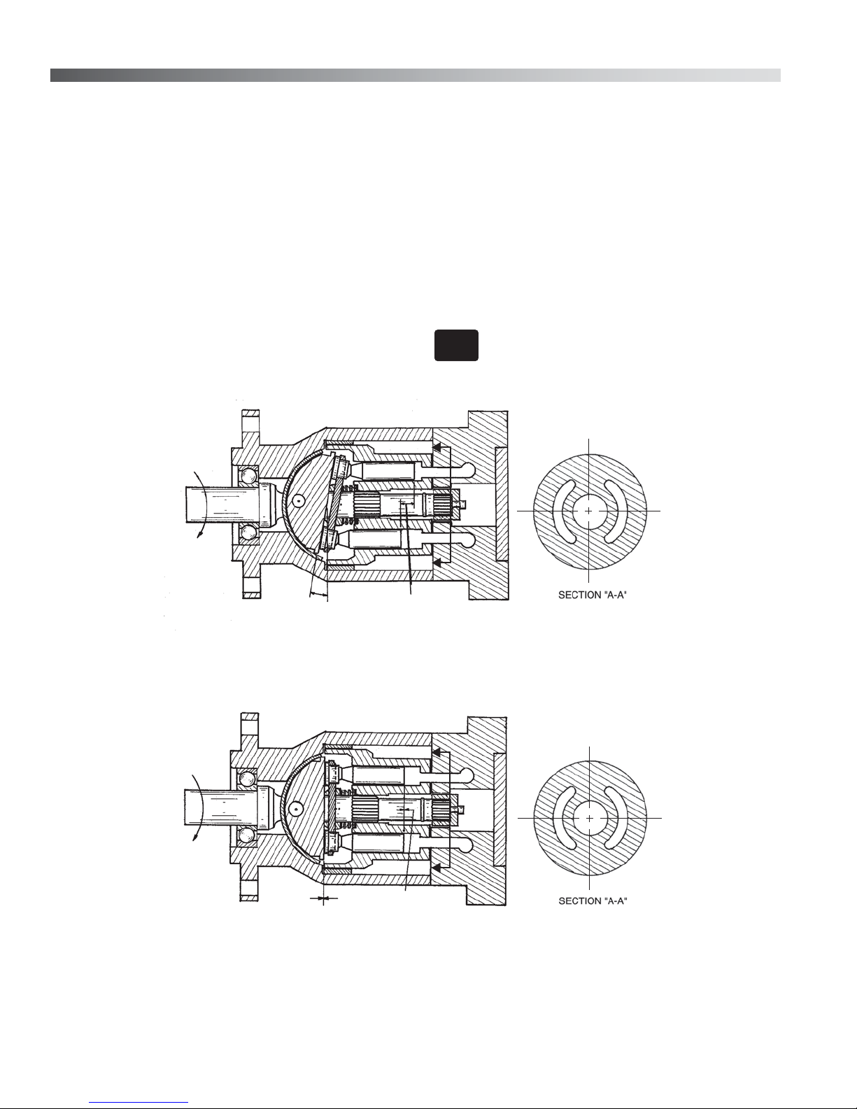
Position B/2, Pump During One Half Delivery
from PORT B - Figure 4
Position N, Pump in Neutral, No Stroke, No
Delivery - Figure 5
This illustration shows that the angle (E) of the
swashblock determines the length of the piston
stroke (F), (the difference between outermost and
innermost position) which determines the amount
of delivery from the pump. In this case, the stroke
angle (E) is one-half of the stroke, which means the
piston stroke is one-half and the pump delivery is
one-half.
IN
OUT
Neutral position results when the control centers
the swashblock. The swashblock angle (G) is now
zero and swashblock face is parallel to the cylinder
face. There is no inward or outward motion of the
pump pistons as piston shoes rotate around the
swashblock face. With no inward and outward
motion or no stroke (H) NEUTRAL, no fluid is being
displaced from the piston bores to the crescents in
the valve plate and there is no delivery from pump
ports.
NOTE
A
Illustration reference numbers match the
part item number in the parts list.
A
B
A
E
F
OILG-0002
Figure 4. Position B/2, Pump During One Half Delivery from Port B
A
NEUTRAL
A
NEUTRAL
A
H
G
B
OILG-0003
Figure 5. Position N, Pump in Neutral, No Stroke, No Delivery
8 THE OILGEAR COMPANY Bulletin 947023
Refer to SPECIFICATIONS

SPECIFICATIONS
NOTE
Refer to reference material, pump control
material and individual application circuit
for exceptions.
THEORETICAL
Unit
PVG 048 2.93 48,0 5000 344,8 5800 400,0 21.1 79,9 2700 73 54,5
PVG 065 3.98 65,0 5000 344,8 5800 400,0 28.8 108,9 2700 100 74,6
PVG 065 4.60 75,4 3750 258,6 4250 293,1 33.3 126,0 2700 89 66,4
MAXIMUM
DISPLACEMENT
3
/rev
in
ml/rev psi bar psi bar gpm l/mi rpm hp kw
Case pressure should be less than 25 psi (1,7 bar). For higher pressure, consult factory.
RATED
CONTINUOUS
PRESSURE
Higher speeds available - consult factory.
MAXIMUM
PRESSURE
FLOW RATE
1800 rpm rated
continuous pressure
and 14,7 psia (bar abs)
inlet condition
at
MAXIMUM
SPEED
Table 1. Nominal Performance Data with 150-300 SSU Viscosity Fluids
Unit
PVG 048, 065, 075 12.0 304,8 6.9 175,3 6.3 160,0 66* 30 SAE “B” 2 bolt
All dimensions (without controls) are approximate. For detailed dimensions, contact your Oilgear Representative.
* Weight with P Control and rear port valve plate
Length Width Height Weight
inches mm inches mm inches mm lbs. kg
POWER
INPUT at rated
continuous
pressure &
1800 rpm
Face Mounting
Table 2. Nominal Dimensions and Weights Without Controls
Refer to installation drawings for more detailed dimensions and port configurations.
Bulletin 947023 THE OILGEAR COMPANY 9
 Loading...