

OIC Korea CMK-01 Installation And User Manual
Installation and User’s Guide
CMK-01 CEILING MOUNT
FLAT LCD DISPLAY MOUNT MODEL
Installation and User’s Guide
http://www.oickorea.com
All contents of this document may change without prior notice, and actual product appearance may differ
from that depicted herein

http://www.oickorea.com
Installation and User’s Guide
Warning Statements
The wall, floor or ceiling should be capable of supporting a weight of at least five (5)
times the monitor’s weight. If it cannot, the wall, floor or ceiling must be reinforced.
Proper installation procedure by qualified personnel as outlined in the installation
instructions must be adhered to Failure to do so could result in serious personal injury.
CAUTION! The entire installation instructions should be fully read and understood,
including all of the safety symbols and safety preca utions before beginnin g installation.
The installation instructions should be read, understood and followed to prevent
personal injury or proper damage. Keep these installation instructions in an easily
accessible location for future reference.
CAUTION! The ceiling structure must be capable of supporting a ma ximum weight of
400 lbs. If not, the ceiling must be reinforced. Proper installation pr ocedure b y qualifie d
personnel as outlined in the installation instructions must be adhered to. Failure to do
so could result is serious personal injury.
CAUTION! Make sure to hold the plasma display, or projector, securely and remove it
from the mount to make the height adjustment prior to loosening the adjustment
screws. Do not remove the screws completely from the extension loosen all at once.
Loosen, remove, adjust then re-tighten the screws. Failure to do so could result in
injury and or damage to the plasma display or projector.
Indicates that the power plug is to be disconnected from the power outlet.
Safety precautions must be taken at all times.
Warning and caution in general
Tel: 82-70-7510-2809 / Fax: 82-70-8240-4403 / Email: sales@oickorea.com
pg2
r
r
p
g
j
g
http://www.oickorea.com
Installation and User’s Guide
CMK-01 Installation
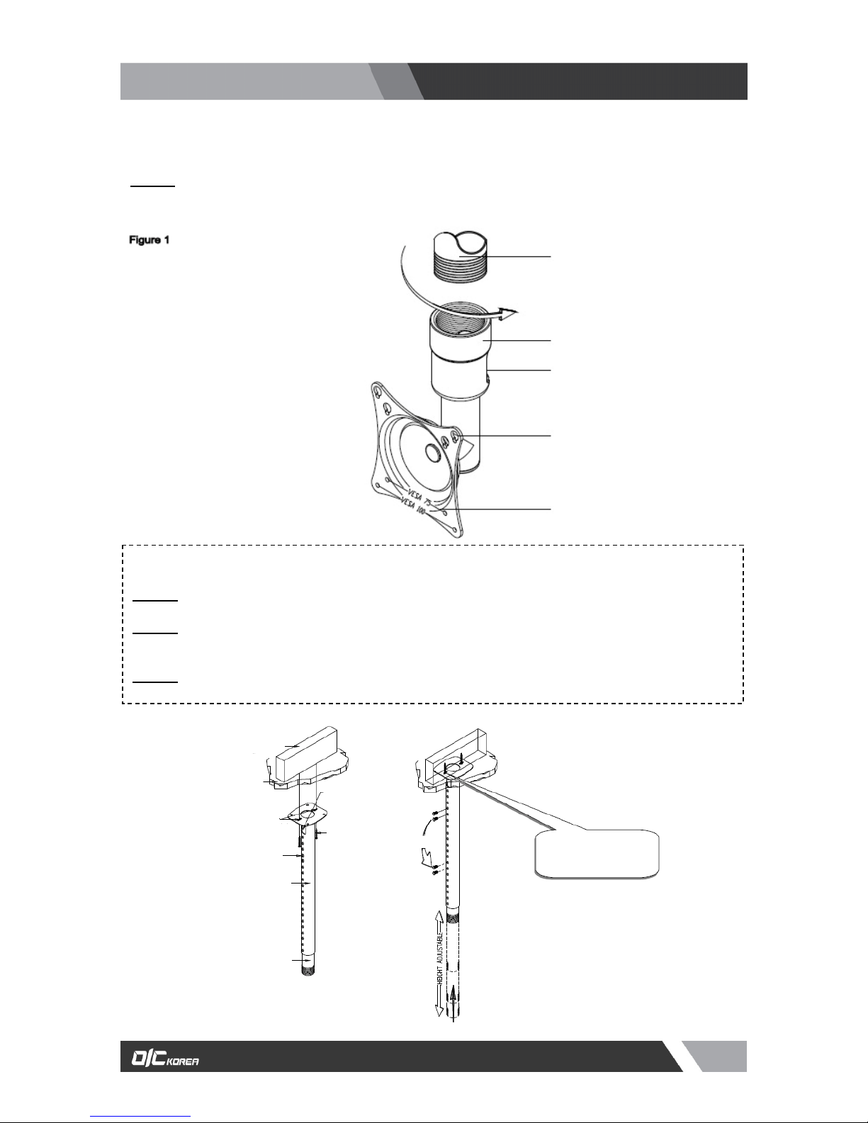
STEP1
Screw the CMK-01 coupling adapter to the adjustable suspension adapters or 1½" (NTP) Pipe.
Secure the coupling with the M6 security screw (supplied). Figure 1.
Couple
Couple
Swivel lock (Located
inside Cou
ler)
Keyhole mounting
opening
VESA 75 / 100
Mounting points
Adjustable Ceiling Adapter
Single Stud Installation
STEP2
Secure the ceiling plate to the ceiling structure (see WARNING).
STEP3
Use suitable hardware (commercially available) depending on your installation environment to
secure the two (2) mounting points found on the ceiling plate to the ceiling structure (Figure 2).
STEP4
Refer to ceilin
adapter installation instructions.
Figure 2
Minimum of 2” x 4”
Use the two (2) slots on the ceiling
Plate for single stud mounting
Ceiling structure
Adjustment screw
Upper tube
Cable access openin
(Commercially
Available) Suitable
Hardware minimum
of 1/4” x 2” Lag bolt
required
Relocate ad
ustment screw
This hardware is commercially
available and is not included
in the hardware pack.
Lower tube
Tel: 82-70-7510-2809 / Fax: 82-70-8240-4403 / Email: sales@oickorea.com
pg3
 Loading...