

OHTAKE SS, SS-12, SS-23 Operation Manual

16,50$(
4GCFVJGUGKPUVTWEVKQPUHQTVJGRTQRGTWUGQHVJKUOCEJKPG
#HVGTJCXKPITGCFVJGUGKPUVTWEVKQPUMGGRVJGOKPCEQPXGPKGPVRNCEGUQ[QW
QTVJGQRGTCVQTECPTGHGTVQVJGOYJGPGXGTPGEGUUCT[
䠪䠯䠮䠥㻌㼀㼥㼜㼑
$XWRPDWLF6FUHZ)HHGHU
ὀព㸟㸸www.ohtake-root.co.jp ࡀᙜ♫၏୍ࡢ HP ࢻࣞࢫ࡛ࡍࠋ
ᘢ♫ࡢྡࢆ㦄ࡿഇࢧࢺࡈὀពୗࡉ࠸ࠋ⌧ᅾࠊᙜ♫ࡣ୰ᅜᅜෆᨭᗑࡣࡈࡊ࠸ࡲࡏࢇࠋ
ྛ栦ᐈ実ὀព㸸ࠕwww.ohtake-root.co.jp ᩎྖ၏୍ⓗᐁ᪉⨒❰㸪
┠๓㸪ᩎྖᅾ୰ᅜἐ᭷≆⢬ᡤ宻ⓗ୰ᅜᐁ⨒ࠋࠖ
ATTENTION : www.ohtake-root.co.jp is the only web site associated with our company.
We do not have any branches in China.
Operation Manual
・ Read these instructions for the proper use of this machine.
・ After having read these instructions, keep them in a convenient
place so you or the operator can refer to them whenever necessary.
自動ネジ供給機
SS
Series
Automatic Screw Feeder
NSN1MA01
(Maintenance)
Mb

Contents
1. OVERVIEW OF THIS MACHINE -------------------- 1
2. BEFORE USE -------------------------------------------- 1
3. OPERATING PRECAUTIONS ----------------------- 2
4. NAMES OF MACHINE PARTS ---------------------- 5
5.
ADJUSTMENTS AND CHECKS BEFORE USE-------- 7
6. OPERATING INSTRUCTIONS---------------------- 17
OVERVIEW OF THIS MACHINE
1.
Thank you very much for selecting our Automatic Screw Feeder "SS series ".
This machine can line up screws (Type M1 - M3) and supplies them one by one to help
7. MISCELLANEOUS----------------------------------------- 19
8. PARTS ADJUSTMENTS AND REPLACEMENTS---20
9. TROUBLESHOOTING------------------------------------- 23
10. SPECIFICATIONS ----------------------------------------- 28
11. EXTERNAL DIMENTIONS-------------------------------- 29
12. WARRANTY ------------------------------------------------- 30
the efciency of screw fastening work.
Different sizes of screws can be used by changing the rail and passage plate.
It can be used wherever there is a power source for an AC adapter.
BEFORE USE
2.
Please check for the following accessories before operating the machine.
Instruction Manual 1 copy
*
Hexagonal Wrench 1 piece
*
Ground wire 1 piece
*
*The design, performance and specications are subject to change without prior notice for the
sake of improvement.
AC Adapter 1 unit
*
Screwdriver 1 piece
*
- 1 -
- 2 -
OPERATING PRECAUTIONS
3.
This manual contains safety alert symbols and signal words to help prevent injuries
to the user or damage to property.
Indications
◎
WARNING
This indicates there is a chance of death, serious injury or re if the instructions
are not followed.
CAUTION
Symbols indicating type of danger and preventative measures
◎
Prohibited operation. Never do this!
Do not disassemble, modify or repair.
Do not touch with wet hands.
This indicates to stop operations.
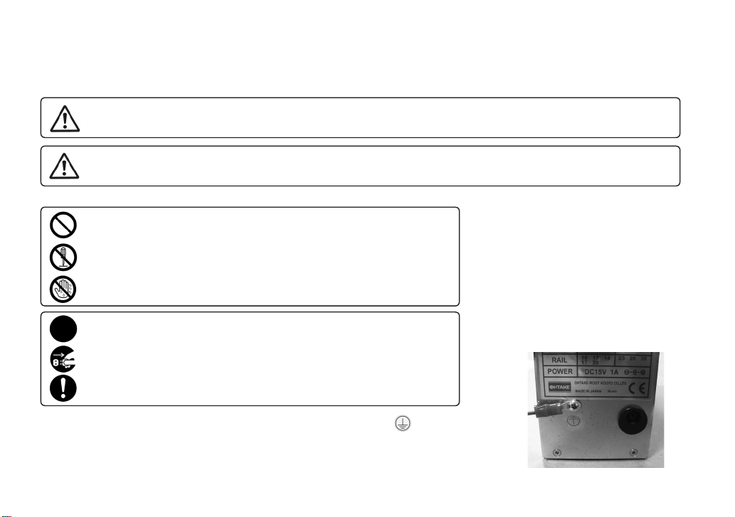
Unplug power supply from wall outlet.
General caution.
Attach the ground wire by loosening the screw near the mark of the equipment.
This indicates there is a chance of personal injury or damage to property
if the instructions are not followed.
the bottom of the main body
- 3 -
WARNING
Do not disassemble the AC adapter as there is a risk of electric shock, re or malfunction.
Do not damage, alter or change the power cord. Do not place heavy objects on the cord.
Do not pull hard on the cord or twist the cord as it could be damaged, thereby causing a risk
of re or electric shock.
Do not handle the AC adapter with wet hands as it could cause an electric shock.
When using an outlet with AC100~240V, don't overload the electrical circuit.
Do not modify or remodel this machine as this may cause a re or electric shock.
Do not operate this machine near ammable liquids, gasses or materials as there could
be a risk of re or explosion.
Stop operating the machine and unplug the AC adapter from the wall outlet when you detect overheating,
smoke, a pungent odor or any other unusual condition, as there may be a risk of re or electric shock. Contact
the dealer, from which you purchased the machine, and have
it examined and repaired.
In the case of a thunderstorm, stop operating the machine, turn off the power and unplug
the AC adapter from the wall outlet. If there is lightning and thunder nearby, move away from the machine and
do not touch it or the AC adapter.
After the thunder stops, and when it is safe to do do so, check the machine. If there is any abnormality, contact
your dealer.
When performing maintenance, changing parts or when you sense an abnormality in the machine, turn the
power off and pull the AC adapter from the wall outlet.
In addition, there are parts that become hot in the circuit board. When performing maintenance around the circuit
board, turn off the power for at least 5 minutes before performing work. There is a risk of burns.
- 4 -
CAUTION
Use only the AC adpater supplied with this machine otherwise it may result in a re
or electric shock.
Do not install this machine in an unstable location otherwise it may fall causing damage or injury.
Always operate the machine with the upper cover in place, otherwise it may result in injury.
Do not allow any foreign material to enter the machine while in operation.
Do not put your ngers into the machine while in operation, otherwise an injury will result.
Do not operate this machine in overly humid or dusty conditions.
Keep the socket plug clean at all times otherwise it may cause a re or electric shock.
When moving the machine, always disconnect the AC adapter from the wall outlet or it may result in damage to
the cord, or cause a re or electric shock.
Turn off the machine and unplug the AC adapter from the wall outlet during closing hours
or if the machine will be unused for any extended period of time.
When moving the machine, be sure to hold it with both hands and be careful not to drop it.
Dropping the machine at your feet may cause injury.
Do not operate the machine with tension on the AC adapter cord.
Keep the cord loose and untangled.
Do not bend, alter or damage the rail. Do not apply any oil. It is recommended that the user
clean the rail periodically.
Do not use any screw that is out of the specied range nor any screw that is oily or dirty.
- 5 -
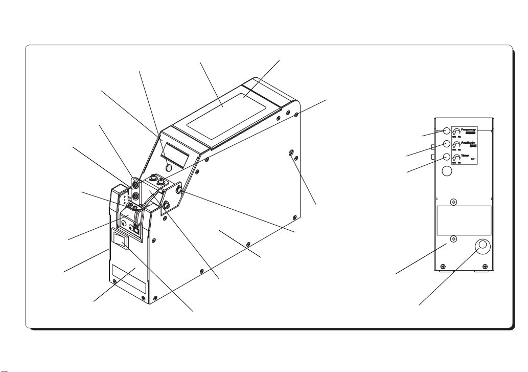
3. Part Names and Descriptions
Center cover
4: Bit guide width
adjustment screw
Bit guide plate
9: Stopper
8: Rail
Left cover
Front cover
2: Front Rail xing screw
1: Scooping chamber
Bit guide Assembly
7: Power switch
Scooping chamber cover
5: Bit guide depth adjustment screw
11: Amplitude control dial
3: Rear: Rail xing screw
6: Bit guide height adjustment screw
Right cover
10: Vibrational frequency control dial
12: Timer control dial
Rear cover
13: DC jack
Back View

- 6 -
Part Names Descriptions
1. Scooping chamber
2. Front Rail xing screw
3. Rear Rail xing screw
4. Bit guide width adjustment screw
5. Bit guide depth adjustment screw
6. Bit guide height adjustment screw
7. Power switch
8. Rail
9. Stopper
10. Vibrational frequency control dial
11. Amplitude control dial
12. Timer control dial
13. DC jack
Place screws in this chamber.
Loosen this to change the rail.
Loosen this to change the rail.
Loosen this to adjust the bit guide width according to the bit diameter.
Loosen this to adjust the bit guide depth according to the screw diameter.
Loosen this to adjust the bit guide height according to the screw position.
* Lift the bit guide before removing or attaching the rail.
Turns the power to the machine on and off.
Set the rail according to the diameter of the screws you are using.
Stops screws at the tip of the rail.
Controls the vibrational frequency using a precision screw driver.
Controls the amplitude using a precision screw driver.
Controls the screw feeding (stop) time using a precision screw driver.
*The machine will stop feeding screws when they ll up the rail.
Connect the AC adapter included in the package.
- 7 -
5. Set Up and Adjustment
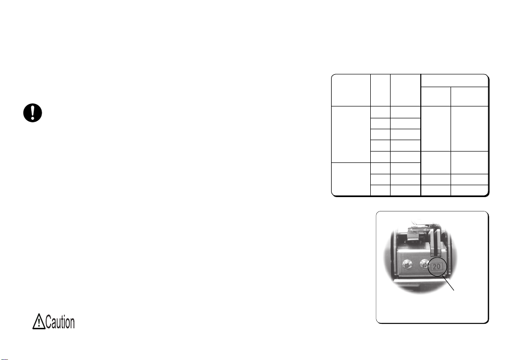
5 - 1. Model Type
● Select the screwdriver bit according to the nominal diameter of screws you
are using. Refer to the label number on the rail. (See Picture 1)
● The machine is adjusted in accordance with model No. (screw
size:φ1.0 - 1.7 [cylinder head screw] /φ2.0 - 3.0 [pan head screw]) be-
fore shipment.
● Screws can generally be used without further adjustment after the initial
adjustment. However, if you are using screws outside the specications in
this manual, the machine may not work properly.
In this case check and
readjust the following:
○ Screw amount ○ Brush
○ Passing plate and slide plate ○ Vibrational frequency
○ Bit guide ○ Timer
○ Sensor voltage level
● The machine can handle several screw diameters simply by changing rails.
After changing the rail, ne-tune each part. Adjustment procedures are
explained on the following pages. Please read these thoroughly before
adjustment.
Be sure to turn off the machine before adjustment.
Model No.
SS-12
SS-23
Lab el
No.
10
12
14
17
20
23
26
30
Nominal
Screw
Diameter
φ1.
0
φ1.
2
φ1.
4
φ1.
7
φ2.
0
φ2.
3
φ2.
6
φ3.
0
Screwdriver Bit Size
Bit Tip
Diameter
φ1.
φ2.
φ
φ3.
5
№ 0
№
0
№
3.0
№
2
Label Number
Picture 1
Cross
Slot No.
or
1
0
1
or
1
2

- 8 -
5 - 2. Brush Height Adjustment
No adjustment is necessary if the tip of the brush touches the screw head in the rail groove and rotates when the ma-
chine is turned on.
● Turn the machine off before adjusting the brush height.
● Loosen the brush height adjustment screws to adjust the brush height. (See Picture 4-1)
● Move the brush manually to check that the brush touches heads of the screws in the rail groove. (See Picture 4-2) If
the brush position is too high, screws in incorrect positions cannot be caught. If the brush position is too low, it may
sweep even correctly positioned screws from the rail or it may stop rotating.
4-1
ScrewsBrush height adjustment screws
Picture 4
4-2
Brush
Just touching
- 9 -
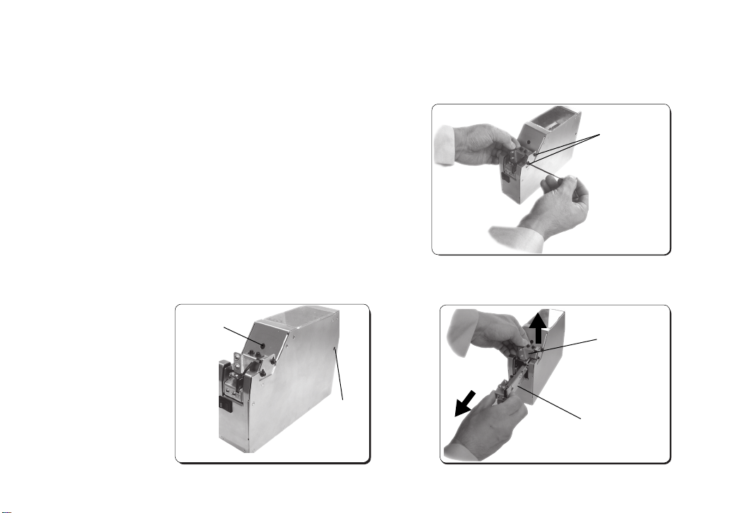
5 - 3. Height Adjustment of Passing and Holding Plates (How to Remove the Rail)
● If screws stop before reaching the stopper, adjust both the passing and holding plates.
Note:
Be sure to eject all screws from the before replacing the rail.
● Loosen the bit guide height adjustment screws. (See Picture 5)
● Slightly loosen the front and rear rail xing screws. (See Picture 6)
● Lift the bit guide “Assembly” and pull the rail out in a horizontal direction. (See Picture 7)
(Front) rail
xing screw
(Right under)
(Rear) rail
xing screw
Picture 6
Bit guide height
adjustment screws
Picture 5
Bit guide “Assembly”
Rail
Picture 7
 Loading...