

Page 1

16,50$(
4GCFVJGUGKPUVTWEVKQPUHQTVJGRTQRGTWUGQHVJKUOCEJKPG
#HVGTJCXKPITGCFVJGUGKPUVTWEVKQPUMGGRVJGOKPCEQPXGPKGPVRNCEGUQ[QW
QTVJGQRGTCVQTECPTGHGTVQVJGOYJGPGXGTPGEGUUCT[
䠪䠯䠮䠥㻌㼀㼥㼜㼑
$XWRPDWLF6FUHZ)HHGHU
ὀព㸟㸸www.ohtake-root.co.jp ࡀᙜ♫၏୍ࡢ HP ࢻࣞࢫ࡛ࡍࠋ
ᘢ♫ࡢྡࢆ㦄ࡿഇࢧࢺࡈὀពୗࡉ࠸ࠋ⌧ᅾࠊᙜ♫ࡣ୰ᅜᅜෆᨭᗑࡣࡈࡊ࠸ࡲࡏࢇࠋ
ྛ栦ᐈ実ὀព㸸ࠕwww.ohtake-root.co.jp ᩎྖ၏୍ⓗᐁ᪉⨒❰㸪
┠๓㸪ᩎྖᅾ୰ᅜἐ᭷≆⢬ᡤ宻ⓗ୰ᅜᐁ⨒ࠋࠖ
ATTENTION : www.ohtake-root.co.jp is the only web site associated with our company.
We do not have any branches in China.
Operation Manual
・ Read these instructions for the proper use of this machine.
・ After having read these instructions, keep them in a convenient
place so you or the operator can refer to them whenever necessary.
自動ネジ供給機
SS
Series
Automatic Screw Feeder
NSN1MA01
(Maintenance)
Mb
Page 2

Contents
1. OVERVIEW OF THIS MACHINE -------------------- 1
2. BEFORE USE -------------------------------------------- 1
3. OPERATING PRECAUTIONS ----------------------- 2
4. NAMES OF MACHINE PARTS ---------------------- 5
5.
ADJUSTMENTS AND CHECKS BEFORE USE-------- 7
6. OPERATING INSTRUCTIONS---------------------- 17
OVERVIEW OF THIS MACHINE
1.
Thank you very much for selecting our Automatic Screw Feeder "SS series ".
This machine can line up screws (Type M1 - M3) and supplies them one by one to help
7. MISCELLANEOUS----------------------------------------- 19
8. PARTS ADJUSTMENTS AND REPLACEMENTS---20
9. TROUBLESHOOTING------------------------------------- 23
10. SPECIFICATIONS ----------------------------------------- 28
11. EXTERNAL DIMENTIONS-------------------------------- 29
12. WARRANTY ------------------------------------------------- 30
the efciency of screw fastening work.
Different sizes of screws can be used by changing the rail and passage plate.
It can be used wherever there is a power source for an AC adapter.
BEFORE USE
2.
Please check for the following accessories before operating the machine.
Instruction Manual 1 copy
*
Hexagonal Wrench 1 piece
*
Ground wire 1 piece
*
*The design, performance and specications are subject to change without prior notice for the
sake of improvement.
AC Adapter 1 unit
*
Screwdriver 1 piece
*
- 1 -
Page 3
- 2 -
OPERATING PRECAUTIONS
3.
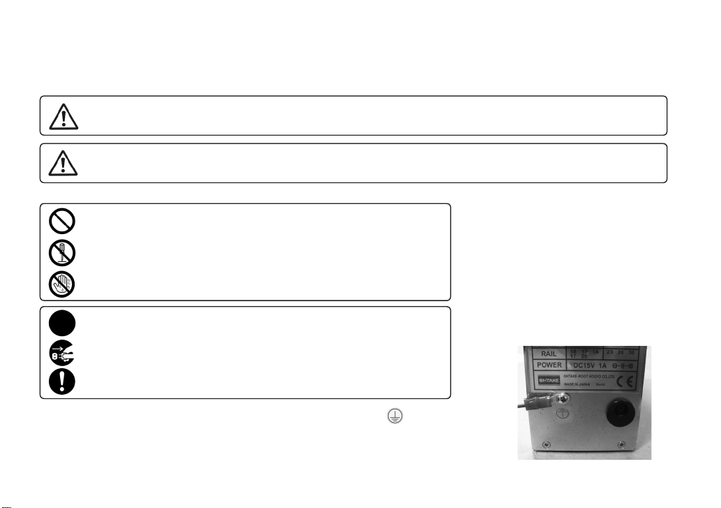
This manual contains safety alert symbols and signal words to help prevent injuries
to the user or damage to property.
Indications
◎
WARNING
This indicates there is a chance of death, serious injury or re if the instructions
are not followed.
CAUTION
Symbols indicating type of danger and preventative measures
◎
Prohibited operation. Never do this!
Do not disassemble, modify or repair.
Do not touch with wet hands.
This indicates to stop operations.
Unplug power supply from wall outlet.
General caution.
Attach the ground wire by loosening the screw near the mark of the equipment.
This indicates there is a chance of personal injury or damage to property
if the instructions are not followed.
the bottom of the main body
Page 4
- 3 -
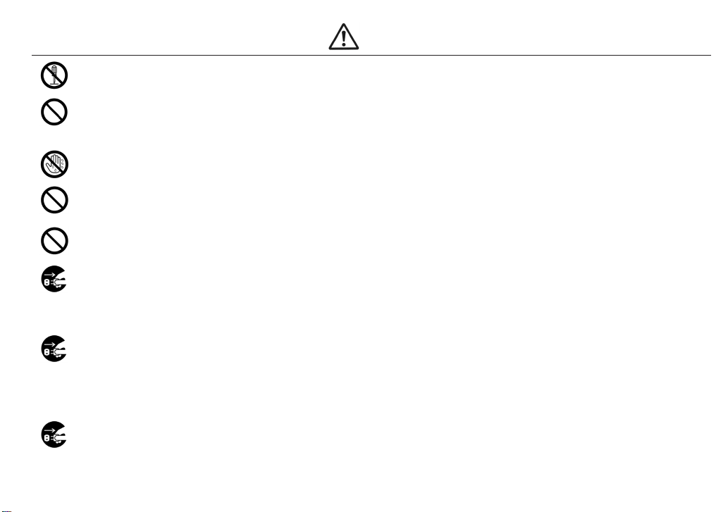
WARNING
Do not disassemble the AC adapter as there is a risk of electric shock, re or malfunction.
Do not damage, alter or change the power cord. Do not place heavy objects on the cord.
Do not pull hard on the cord or twist the cord as it could be damaged, thereby causing a risk
of re or electric shock.
Do not handle the AC adapter with wet hands as it could cause an electric shock.
When using an outlet with AC100~240V, don't overload the electrical circuit.
Do not modify or remodel this machine as this may cause a re or electric shock.
Do not operate this machine near ammable liquids, gasses or materials as there could
be a risk of re or explosion.
Stop operating the machine and unplug the AC adapter from the wall outlet when you detect overheating,
smoke, a pungent odor or any other unusual condition, as there may be a risk of re or electric shock. Contact
the dealer, from which you purchased the machine, and have
it examined and repaired.
In the case of a thunderstorm, stop operating the machine, turn off the power and unplug
the AC adapter from the wall outlet. If there is lightning and thunder nearby, move away from the machine and
do not touch it or the AC adapter.
After the thunder stops, and when it is safe to do do so, check the machine. If there is any abnormality, contact
your dealer.
When performing maintenance, changing parts or when you sense an abnormality in the machine, turn the
power off and pull the AC adapter from the wall outlet.
In addition, there are parts that become hot in the circuit board. When performing maintenance around the circuit
board, turn off the power for at least 5 minutes before performing work. There is a risk of burns.
Page 5
- 4 -
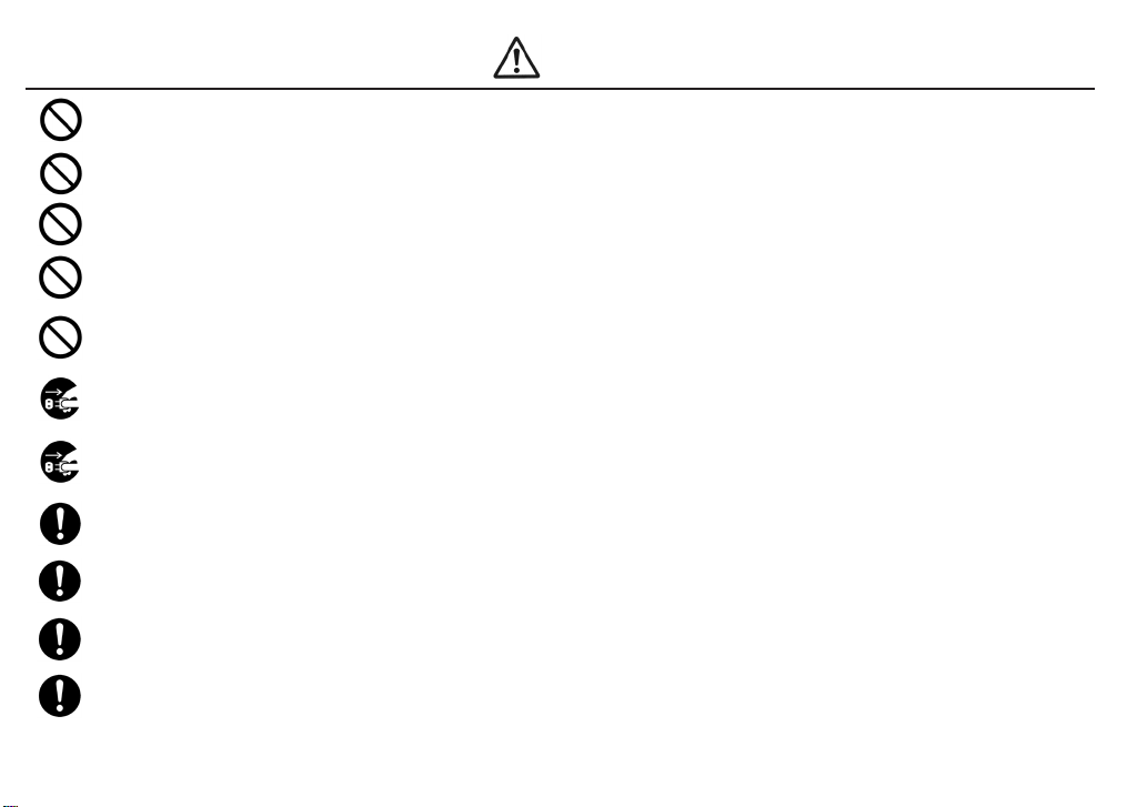
CAUTION
Use only the AC adpater supplied with this machine otherwise it may result in a re
or electric shock.
Do not install this machine in an unstable location otherwise it may fall causing damage or injury.
Always operate the machine with the upper cover in place, otherwise it may result in injury.
Do not allow any foreign material to enter the machine while in operation.
Do not put your ngers into the machine while in operation, otherwise an injury will result.
Do not operate this machine in overly humid or dusty conditions.
Keep the socket plug clean at all times otherwise it may cause a re or electric shock.
When moving the machine, always disconnect the AC adapter from the wall outlet or it may result in damage to
the cord, or cause a re or electric shock.
Turn off the machine and unplug the AC adapter from the wall outlet during closing hours
or if the machine will be unused for any extended period of time.
When moving the machine, be sure to hold it with both hands and be careful not to drop it.
Dropping the machine at your feet may cause injury.
Do not operate the machine with tension on the AC adapter cord.
Keep the cord loose and untangled.
Do not bend, alter or damage the rail. Do not apply any oil. It is recommended that the user
clean the rail periodically.
Do not use any screw that is out of the specied range nor any screw that is oily or dirty.
Page 6
- 5 -
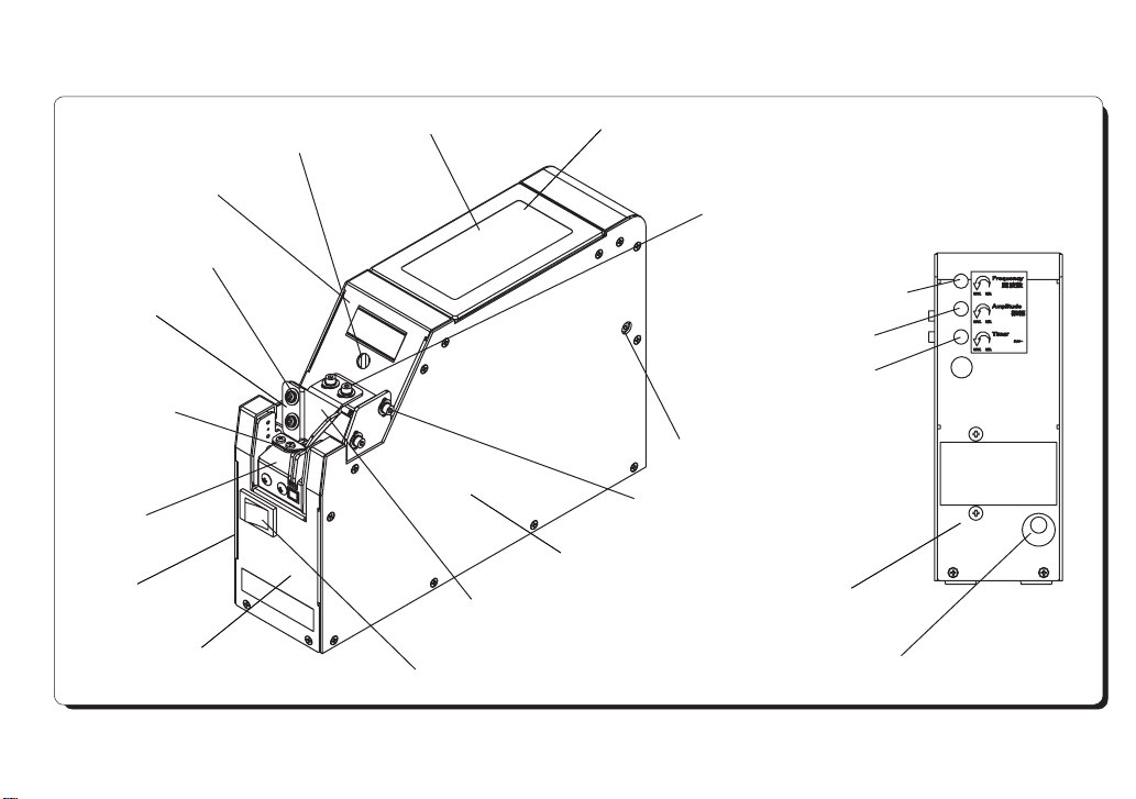
3. Part Names and Descriptions
Center cover
4: Bit guide width
adjustment screw
Bit guide plate
9: Stopper
8: Rail
Left cover
Front cover
2: Front Rail xing screw
1: Scooping chamber
Bit guide Assembly
7: Power switch
Scooping chamber cover
5: Bit guide depth adjustment screw
11: Amplitude control dial
3: Rear: Rail xing screw
6: Bit guide height adjustment screw
Right cover
10: Vibrational frequency control dial
12: Timer control dial
Rear cover
13: DC jack
Back View
Page 7

- 6 -
Part Names Descriptions
1. Scooping chamber
2. Front Rail xing screw
3. Rear Rail xing screw
4. Bit guide width adjustment screw
5. Bit guide depth adjustment screw
6. Bit guide height adjustment screw
7. Power switch
8. Rail
9. Stopper
10. Vibrational frequency control dial
11. Amplitude control dial
12. Timer control dial
13. DC jack
Place screws in this chamber.
Loosen this to change the rail.
Loosen this to change the rail.
Loosen this to adjust the bit guide width according to the bit diameter.
Loosen this to adjust the bit guide depth according to the screw diameter.
Loosen this to adjust the bit guide height according to the screw position.
* Lift the bit guide before removing or attaching the rail.
Turns the power to the machine on and off.
Set the rail according to the diameter of the screws you are using.
Stops screws at the tip of the rail.
Controls the vibrational frequency using a precision screw driver.
Controls the amplitude using a precision screw driver.
Controls the screw feeding (stop) time using a precision screw driver.
*The machine will stop feeding screws when they ll up the rail.
Connect the AC adapter included in the package.
Page 8
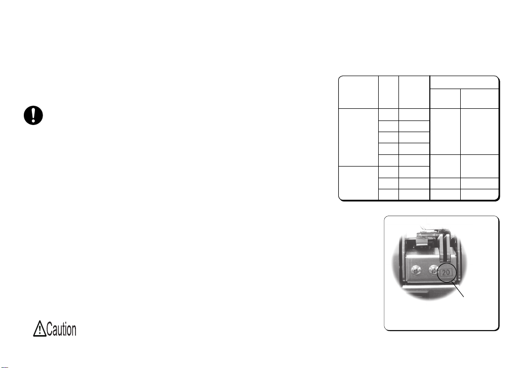
- 7 -
5. Set Up and Adjustment
5 - 1. Model Type
● Select the screwdriver bit according to the nominal diameter of screws you
are using. Refer to the label number on the rail. (See Picture 1)
● The machine is adjusted in accordance with model No. (screw
size:φ1.0 - 1.7 [cylinder head screw] /φ2.0 - 3.0 [pan head screw]) be-
fore shipment.
● Screws can generally be used without further adjustment after the initial
adjustment. However, if you are using screws outside the specications in
this manual, the machine may not work properly.
In this case check and
readjust the following:
○ Screw amount ○ Brush
○ Passing plate and slide plate ○ Vibrational frequency
○ Bit guide ○ Timer
○ Sensor voltage level
● The machine can handle several screw diameters simply by changing rails.
After changing the rail, ne-tune each part. Adjustment procedures are
explained on the following pages. Please read these thoroughly before
adjustment.
Be sure to turn off the machine before adjustment.
Model No.
SS-12
SS-23
Lab el
No.
10
12
14
17
20
23
26
30
Nominal
Screw
Diameter
φ1.
0
φ1.
2
φ1.
4
φ1.
7
φ2.
0
φ2.
3
φ2.
6
φ3.
0
Screwdriver Bit Size
Bit Tip
Diameter
φ1.
φ2.
φ
φ3.
5
№ 0
№
0
№
3.0
№
2
Label Number
Picture 1
Cross
Slot No.
or
1
0
1
or
1
2
Page 9

- 8 -
5 - 2. Brush Height Adjustment
No adjustment is necessary if the tip of the brush touches the screw head in the rail groove and rotates when the ma-
chine is turned on.
● Turn the machine off before adjusting the brush height.
● Loosen the brush height adjustment screws to adjust the brush height. (See Picture 4-1)
● Move the brush manually to check that the brush touches heads of the screws in the rail groove. (See Picture 4-2) If
the brush position is too high, screws in incorrect positions cannot be caught. If the brush position is too low, it may
sweep even correctly positioned screws from the rail or it may stop rotating.
4-1
ScrewsBrush height adjustment screws
Picture 4
4-2
Brush
Just touching
Page 10
- 9 -
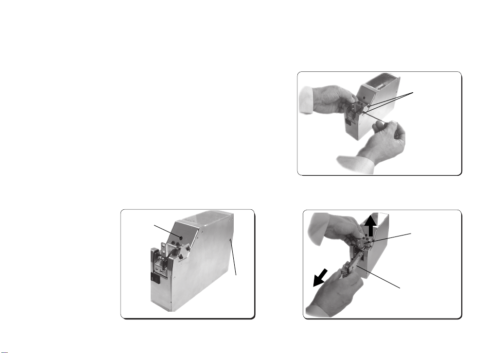
5 - 3. Height Adjustment of Passing and Holding Plates (How to Remove the Rail)
● If screws stop before reaching the stopper, adjust both the passing and holding plates.
Note:
Be sure to eject all screws from the before replacing the rail.
● Loosen the bit guide height adjustment screws. (See Picture 5)
● Slightly loosen the front and rear rail xing screws. (See Picture 6)
● Lift the bit guide “Assembly” and pull the rail out in a horizontal direction. (See Picture 7)
(Front) rail
xing screw
(Right under)
(Rear) rail
xing screw
Picture 6
Bit guide height
adjustment screws
Picture 5
Bit guide “Assembly”
Rail
Picture 7
Page 11
- 10 -
5 - 4. Height Adjustment of Passing and Holding Plates
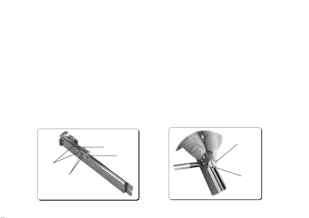
● Both the passing and holding plates are xed to the rail. (See Picture 8)
● Place a screw between the passing plate and the rail grove and adjust the height of the passing plate by loosening the
passing plate xing screw. (See Picture 9) If the gap between the passing plate and the rail groove is too wide, the
screw ow may stop. If the gap is too small, the screw ow may also stop. (Screws cannot pass through the gap.) Ad-
just the height to the exact height of the screw head.
● Optional passing plates for various screw types, including thin head screws, are available. Contact the dealer from
which you purchased the machine with details of the screw size you are planning to use.
Passing
plate
Screw
Holding plate
xing screw
Passing plate
xing screw
Holding plate
Passing
plate
Picture 8
Picture 9
Page 12
- 11 -
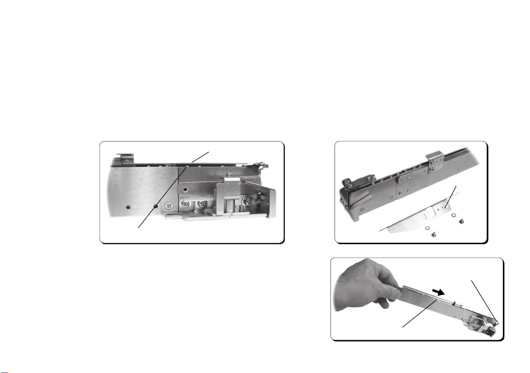
● Put a screw into the rail groove, just beneath the holding plate, and adjust the holding plate height so that there is an
adequate gap between the holding plate and the rail groove for the screw head. Loosen the holding plate xing screw
and adjust the gap between the holding plate and rail groove. (See Picture 10) Removing the holding plate before ad-
justment will allow you to easily place screws into the rail groove easily. (See Picture 11) If the gap between the hold-
ing plate and the rail grove is too wide, screws may fall out. If the gap is too small, the screws may not be able to pass
through. Set the gap to between 0.2 to 0.5mm above screw heads. If you are using long screws, adjust the gap so that
it is a little higher.
Note: When using washer head screws, make the gap wider. If the gap between the holding plate and the rail groove is
not wide enough, washers may become stuck between the holding plate and the rail causing the screw ow to stop.
Holding plate
押え板
Holding plate
Picture 10
Screw
使用ネジ
写真-10
Picture 11
● After adjustment, place a screw into the end of the rail groove. Tilt the
rail and check that the screw moves smoothly to the stopper position.
(See Picture 12)
Stopper
● After checking, reverse the procedure for removing the rail to reattach it.
(Fix the screws when the rail makes contact with the machine.)
Note: If the front and rear rail xing screws are not loosened, the rail can-
not be attached to the correct position.
Picture 12
Screw
Page 13
- 12 -
5 - 5. Rail Vibration Adjustment
● The rail vibration has been adjusted before shipment using screws that correspond to the rail size.
(Refer to the label number on the rail for the nominal screw diameter: e.g. 17 is φ1.7)
● Put 2 or 3 screws into the rail groove and turn the machine on.
● No adjustment is necessary if the screws move to the stopper position smoothly. (See Picture 13)
●When the number of screws is low and no screw is picked up in a given period of time, vibration will become the
maximum and it will stop operation after that. (Refer to 4-2 “Basic Operation.”)Adjustment of volume is not effective
at the time of a forced oscillation.
● After it stops, turn on the machine again and repeat the above procedure.
Screw
Stopper
Adjust the rail vibration so that the screw moves
smoothly in the direction of the arrow.
Picture 13
● Adjustment is necessary if the screw ow is not smooth or if there is too much rail vibration.
○ Adjust the Amplitude control dial on the back of the machine using the precision screwdriver.
○ Adjust the Vibration frequency control dial on the back of the machine using the precision screwdriver and nd the
resonance point.
Adjust these dials to locate the optimum conditions for smooth movement of screws.
● Maximize the amplitude and adjust the vibration frequency to locate the resonance point (frequency when the rail vi-
bration is at a maximum.) Then turn down the amplitude to locate the optimum conditions for smooth movement of
screws.
● Although it is not recommended, the rail vibration can be adjusted while the machine is operating.
● During control dial adjustment, do not force the screwdriver beyond its rotation limits.
Page 14
- 13 -
5 - 6. Bit Guide Adjustment
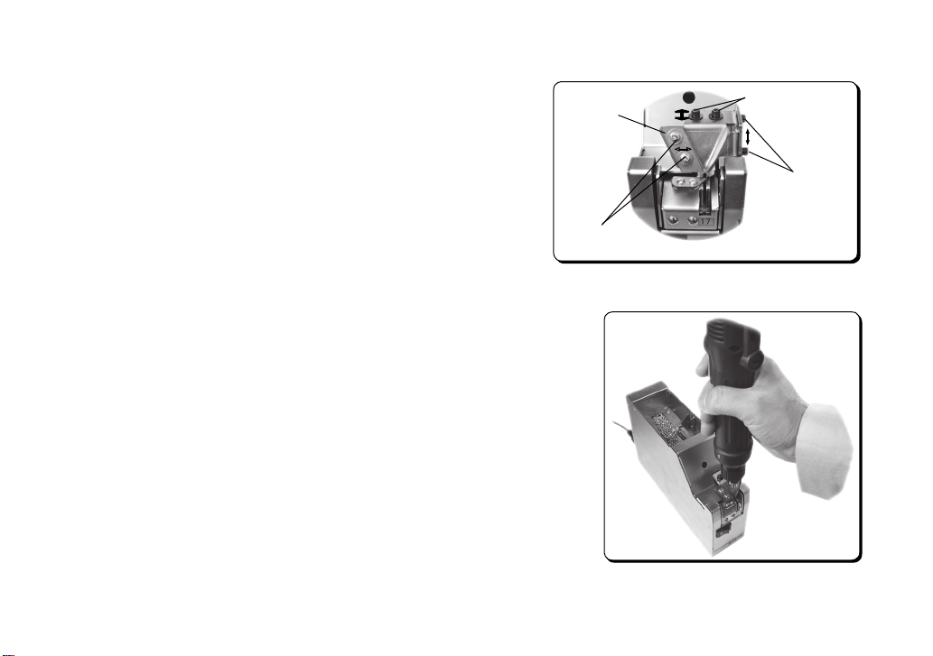
● Bit guide position adjustment is explained below.
Bit guide plate
● Pick up several screws to adjust the bit guide.
● Adjust the bit guide position after loosening the adjustment screws.
(See Picture 14)
Plate adjustment
screws
How to Adjust the Bit Guide Position
● Use the bit guide height adjustment screws to adjust the bit guide height
so that it doesn’t touch the holding plate.
● Use the plate adjustment screws and bit guide width adjustment screws to
adjust the bit guide groove width and position so that the bit guide width
matches the holding plate groove width.
● Fit the screwdriver bit into the bit guide and adjust the bit guide groove
width so that the screwdriver bit moves smoothly. (See Picture 15)
Bit guide depth
adjustment screws
Bit guide height
adjustment screws
Picture 14
Picture 15
Page 15
- 14 -
5 - 7. Timer Adjustment
The machine is equipped with a screw sensor that detects the number of screws on the rail.
If a screw accumulates to some extent on a rail, operation of a scooping block will stop and vibration will stop after
timer set time.
The timer should normally be set to “Min.”
However if screws are moving slowly, it may be necessary to set the timer to “Max.”
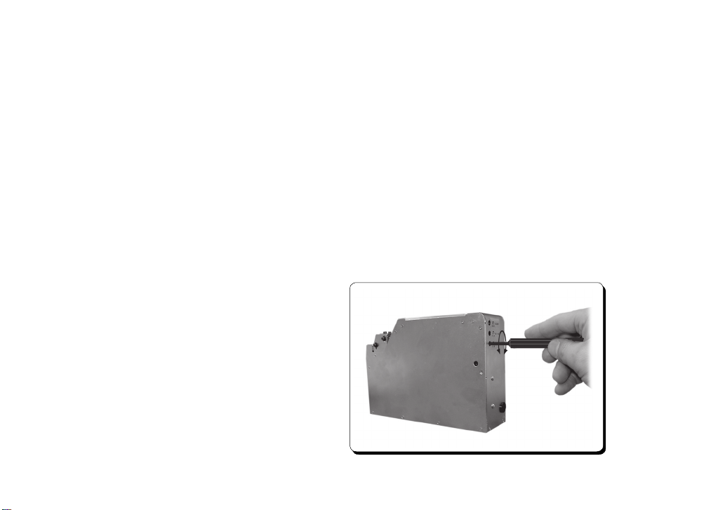
● Adjust the Timer control dial on the back of the machine using a precision screwdriver. (See Picture 16)
● Turn the dial clockwise to reduce the vibration time. Turn it counterclockwise to increase the vibration time.
● During control dial adjustment, do not force the screwdriver beyond its rotation limits.
● Set the timer after checking that the rail is lled and that the screws are properly aligned.
● Use the provided screwdriver for adjusting the timer.
Picture 16
Page 16
- 15 -
5 - 8. Sensor Voltage Level Adjustment
Screws can generally be used without further adjustment after the initial adjustment. However, if you are using screws outside the specications in this manual,
the machine may not work properly. In this case check and readjust the following:
Adjust the sensor levels for when screws are on the rail and for when no screws
are on the rail.
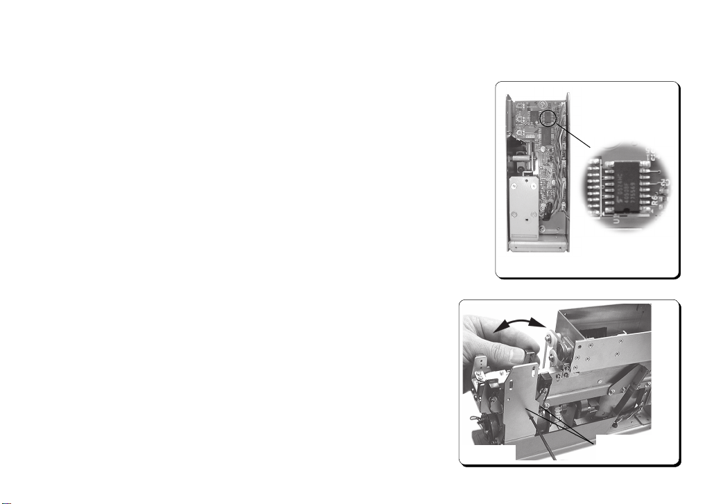
Remove the rear cover of the machine to check the IC on the printed circuit board.
(See Picture 17)
Measure the voltage level using Pins 3, 5, and 7 on the IC4050. Ground the metal
part of the body. (Use testing clips for the voltage measurement. Recommended
item: Testing clip <FP-7> manufactured by Sunhayato Corp.)
*** Screw Sensor Adjustment (Pin 3) ***
The screw sensor detects whether or not there are any screws re-
maining on the rail.
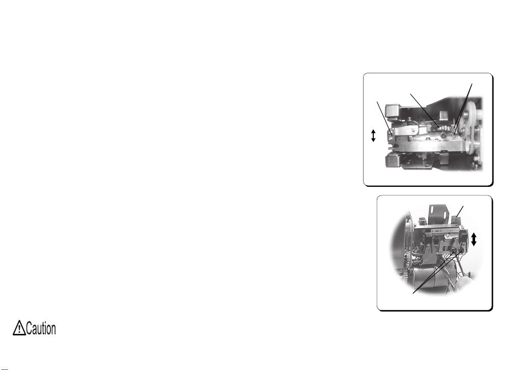
Loosen the light receiving sensor bracket xing screws (2 pcs.) and
adjust the sensor level by rotating the bracket. (See Picture 18)
0.25 – 1.5V: There are no screws remaining on the rail.
3.5V or more: There are screws on the rail.
If the voltage is 2.5V or over, the sensor judges that there are
Picture 18
screws on the rail.
The rear cover is removed.
Closeup
7
5
3
Picture 17
Sensor bracket
xing screws
Page 17
- 16 -
*** Stopper Sensor Adjustment (Pin 5) ***
The stopper sensor detects stopper movement.
Loosen the stopper sensor bracket xing screws (2 pcs) and adjust the light receiving
sensor position horizontally. (See Picture 19)
4.0V or more: Stopper ON
0.2V or less: Stopper OFF
If the voltage is 2.5V or over, the sensor judges that there are screws on the rail.
Stopper
Stopper sensor
bracket
Fixing screws
*** Front Sensor Adjustment (Pin 7) ***
The front sensor detects whether or not there are any screws remaining on the
stopper.
Loosen the front sensor bracket xing screws (2 pcs) and adjust the light receiving
sensor position vertically. (See Picture 20)
0.25 – 1.5V: There are no screws on the stopper.
3.5V or more: There are screws on the stopper.
If the voltage is 2.5V or over, the sensor judges that there are screws remaining on
the stopper.
After checking and adjusting each part, test run the machine using the screws you
actually intend to use.
If the machine does not run properly, repeat the above adjustment as well as rail
position and
vibration adjustments. After the test run, return the sensor wiring to its original
condition.
Do not pinch the wiring and ensure it is clear of the machine’s moving parts.
OFF
ON
Bracket xing
screws
Picture 19
Front sensor
Picture 20
Page 18
- 17 -
6. Basic Operation
The driving motor repeats normal rotation and an inversion for about 2 seconds at a time, and the scooper carries screws
to the rail. The vibrator (solenoid) continuously sends screws to the front stopper to be picked up using the screwdriver.
Note:
If no screws are sent for approximately 10 seconds, vibration of a rail becomes stlonger. (The vibration sound, also, in-
creases; however, this is not a problem.)
If no screw is not detected for about 20 more seconds, then the machine stops operating. When you want to start opera-
tion again, turn the power switch OFF and ON again or a stopper is operated (extraction sensor perception),
6 - 1. Number of Screws
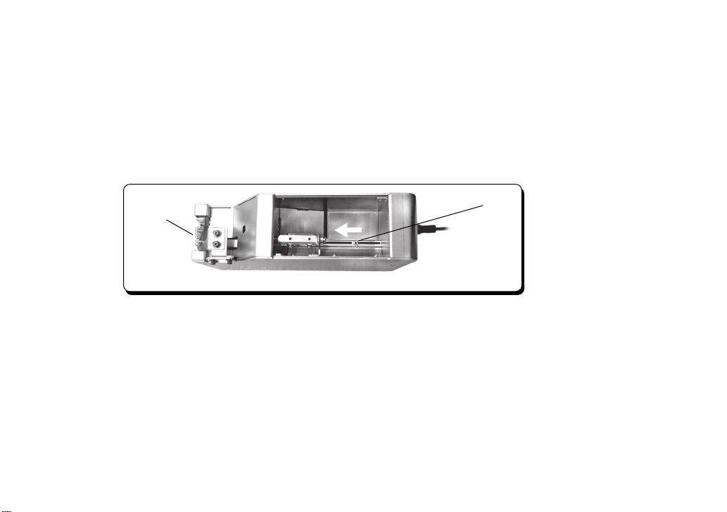
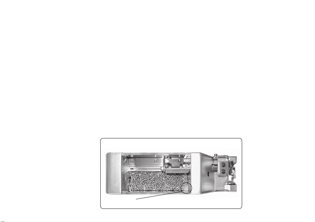
Adjust the number of screws to ensure the proper alignment and smooth ow of screws. (See Picture 2)
● Adjust the scooping chamber to its lowest position by turning the power to the machine on and off.
● Fill the scooping chamber with screws up to 2mm below the rail groove.
● Be sure not to cover the front of the sliding plate with screws.
● Always ensure there are adequate screws for the operation.
View from the Above
Do not cover the front of the sliding plate with screws.
Picture 2
Page 19
- 18 -
6 - 2. Operation Check
● If each part is adjusted appropriately, screws are sent to the stopper.
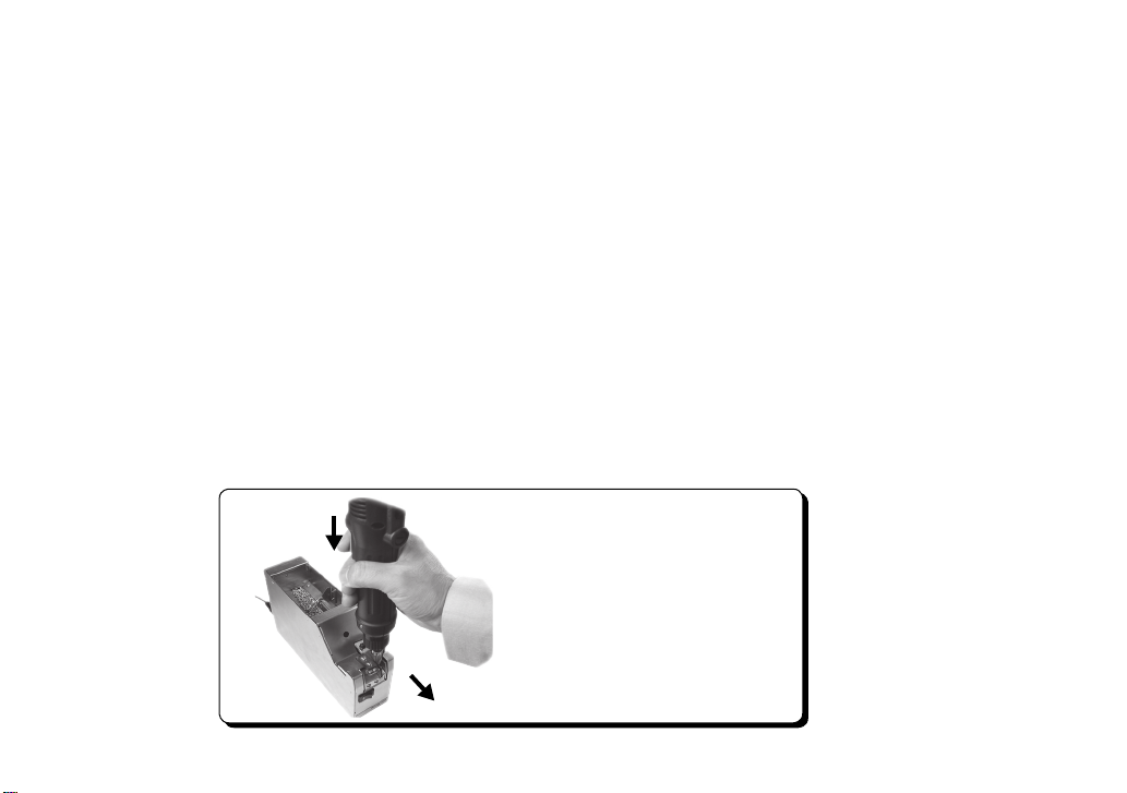
● Pick up screws from the stopper using the electric screwdriver. Using the bit guide as a guide, pull the screwdriver
downward. Fit the screwdriver bit into the cross slot of the screw and then pull the screwdriver toward you in a hori-
zontal direction to pick up the screw. (See Picture 3)
● Do not use force when tting the screwdriver bit to the screw head. This may bend the rail or lead to malfunction of the
machine.
● To t the bit securely into the cross slot of the screw, slightly rotate the screwdriver bit.
● Select the screwdriver bit according to the nominal diameter of the screws you are using. (Refer to “4-1. Model Type.”)
● If screw alignment or ow is abnormal, check and adjust each part. (Refer to “4-1. Model Type”)
● Pu ll the scre wd ri ver do wn wa rd and fit th e
screwdriver bit into the cross slot of the screw.
● Pull the screwdriver toward you in a horizontal
direction to pick up the screw.
Picture 3
Page 20

- 19 -
7. Miscellaneous
7 - 1. Overload Protection Circuit
The machine is equipped with an overload protection circuit.
Normally, the driving motor rotates and sends screws to the rail.
However, if an overload is applied to the machine’s moving parts, the driving motor rotates in the counter
direction for a given length of time and then rotates normally again.
If this action recties the overload, the machine resumes screw feeding; however, if there is still an overload,
the motor continues to rotate in normal and opposite directions and then the power to the motor is cut off.
If the power to the motor is cut off, turn off the machine and remove the cause of overload.
For example, if there are too many screws in the scooping chamber, remove some of them. Remove any
screws stuck in the machine’s moving parts.
After eliminating the cause of overload, turn the machine on and restart operation. (Power reset)
7 - 2. Maintenance
Dust, dirt, or grease in the rail groove may reduce the screw feeding speed.
If dust, dirt, or grease is evident in the rail groove, wipe it with a soft, clean alcohol-soaked cloth. Remove the rail if it is
hard to wipe.
Be sure to turn off the machine and remove all screws from the scooping chamber before removing the rail. (Refer to
Page 9 “4-5-1. Height Adjustment of Passing and Holding Plates (How to Remove the Rail)”)
Please replace the rail if there is noticeable grease, dirt or scratch on it.
Page 21
- 20 -
8. Parts Replacement and Adjustment
Turn off the machine before replacing or adjusting parts.
The brush, driving belt, and driving motor are all consumable parts.
You will need to order another rail if the size of the screw you are using is to be changed.
Read the instructions below thoroughly before adjustment. Be sure to remove all screws from inside the machine before
replacement.
8-1. How to Replace and Adjust the Brush
If the ends of the brush are worn and do not wipe-off the screws that are out of
alignment, replace the brush.
Optional hard brushes are also available. Contact the dealer from which you
purchased the machine for further information.
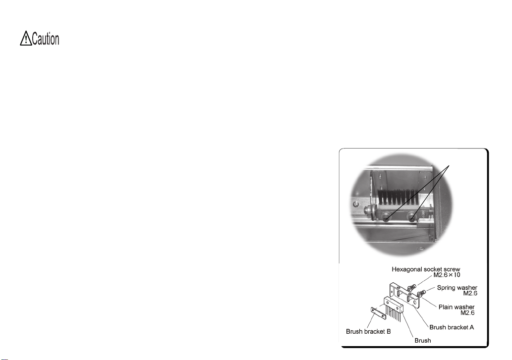
● Turn the machine on and off until the brush comes out to a position where
you can remove the brush xing screws. (See Picture 21)
● Refer to the diagram under Picture 21 to replace the brush.
● Reverse the procedure for removing the brush to attach a new one.
● Refer to Page 8 “Brush Height Adjustment” for adjustment.
Brush Item Nos.: NSN02107 (for Model SS-12)
NSN22001 (for Model SS-23; option for Model SS-12)
Fixing screws
Picture 21
Page 22
- 21 -
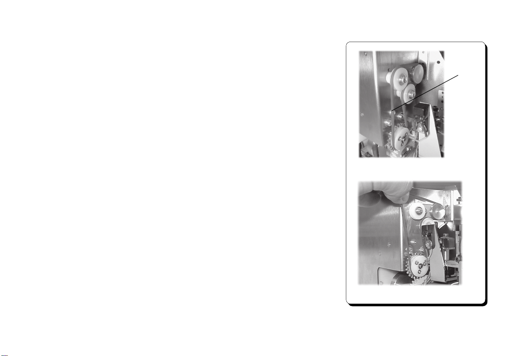
8-2. How to Replace and Adjust the Driving Belt
If the driving belt is worn causing the brush to slip or not rotate properly and
screws that are out of alignment are not being picked up properly, replace the
driving belt.
● Turn the machine off and remove the left and center covers.
● When you remove the covers, you will be able to see the four rollers that the
driving belt is tted around. (See Picture 22)
● Remove the belt with your ngers as shown in Picture 23.
● Reverse this procedure to attach the new belt.
● After attaching the belt, check that each part moves normally.
(See Chapter 4 “Set Up and Adjustment”)
Driving Belt Item No.: NSN03114
Driving belt
Picture 22
Picture 23
Page 23
- 22 -
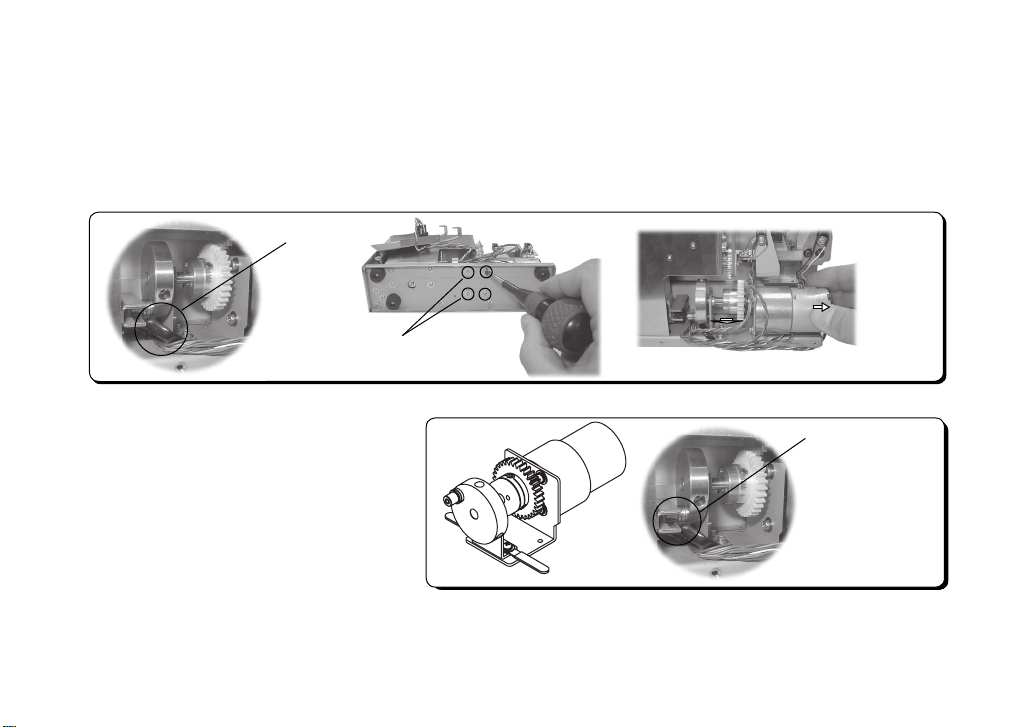
8-3. How to Replace the Main Motor Unit
If the motor is damaged, replace it with a new motor.
● Remove the rail and the front, center, left, and right covers. Loosen the clips (2pcs.) holding the cable.
● Remove the harness (blue and orange) of a motor from a circuit board.
● Remove the motor xing screws (4 pcs.) from the bottom of the body and then pull the motor out in a horizontal
direction from the body. (See Picture 24)
Loosen the wire clips.
Motor xing
screws (4 pcs.)
● R e v erse th e proc e d u re fo r rem o v ing th e
motor to attach the new one.
Note: Do not pinch the motor wiring in order to
ensure it is not damaged.
Main motor unit ltem No.: NSN
03001
Main motor unit
Slightly pull the motor back before
pulling it out from the left side.
During assembly,
enter the roller to
between slit.
Picture 24
Page 24

- 23 -
9. Troubleshooting
Be sure to turn off the machine before checking the problems listed below.
Problem Cause of Problem Troubleshooting
1. The machine does not run after
being turned on.
○ The power is cut off.
○ No screw was picked up from the screw
ho ldin g gro ove f or a g iven p erio d of
time.
○ There are too many screws in the scoop-
ing chamber.
○ An object is stuck inside the machine.
○ AC adapter failure
○ Check that the AC adapter is properly
connected to the power source.
○ Pick up the screw in the screw hold-
ing groove.
○ Adjust the Timer control dial.
○ Reduce the number of screws in the
scooping chamber.
○ Remove the object.
2. The rail does not move back
and forth.
○ An object (e.g. screw) is stuck between
the rail and the body.
○ Even though there is no object stuck be-
tween the rail and the body, it does not
vibrate.
○ Remove the object.
○ Check and adjust the amplitude. If
the rail d oes not vibra te afte r the
adjustment, contact the dealer from
which you purchased the machine
for repair.
Page 25

- 24 -
Problem
3 . Th e f l ow o f s c r e w s h a s
stopped.
Cause of Problem
○ The screws are the wrong size for the rail.
○ T he r e ar e n ot enou g h screw s in the
scooping chamber.
Troubleshooting
○ Use s cre ws appropriate to the rail
size.
○ Place screws into the scooping cham-
ber.
○ A screw is stuck between the passing
plate and the rail groove and the brush
cannot remove it.
○ A screw is stuck on the rail.
○ Adjust the brush.
○ Adjust the passing plate.
○ Place screws into the scooping cham-
ber.
○ Replace the driving belt.
○ Use a hard brush. (optional)
○ Remove the screw.
Follow the procedure below.
Pull up the holding plate and remove
the screw. Then adjust the holding plate position. Be careful not to
scratch the rail.
Page 26

- 25 -
Problem
4. Screws have fallen into the rail
groove.
Cause of Problem
○ The screws are the wrong size for the rail.
○ The screw is shorter than the rail groove
depth.
Troubleshooting
○ Use screws appropriate to the rail size
○ C onta ct the deale r from wh ich y ou
purchased the machine with details of
your screw size.
5 . T h e s c r ew s d o n o t f l ow
smoothly.
○ The gap between the holding plate and
the screw head is too small.
○ Spring washer screws are smaller than
the type specied for the rail being used.
○ There is dust, dirt, or grease on the rail.
○ The rail vibration is insufficient.
(The rail touches the body.)
○ Adjust the holding plate.
○ Adjust the vibration frequency.
○ Tilt the machine slightly.
○ If the speed of the screw flow does
not increase after the above adjust-
ments, contact the dealer from which
you purchased the machine.
○ Wipe the rail with a soft, clean alco-
hol-soaked cloth.
○ Check and adjust the vibration fre-
quency.
○ If the rail touches the body, contact
the dealer from which you purchased
the machine for repair.
○ Replace the driving motor.
Page 27

- 26 -
Problem Cause of Problem
6. Sc rews are inclin ed and pass
through the passing plate too quickly.
○ The passing plate has not been ad-
justed correctly.
○ T h e r e are to o many s c r e w s in th e
scooping chamber.
Troubleshooting
○ Adjust the passing plate.
○ Reduce the number of screws in the
scooping chamber.
7. No screw comes out to the screw
holding groove.
8. The machine stops suddenly.
○ Screws are stuck on the rail.
○ The overload protection circuit was ac-
tivated.
○ There ar e too m a ny scr e w s in t h e
scooping chamber.
○ An object (e.g. screw ) is stuck be-
tween the rail and the body.
○ A screw remains in the stopper for a
given period of time.
○ Adjust the holding plate position.
○ Reset the main power.
○ Eliminate the cause of overload.
○ Reduce the number of screws in the
scooping chamber.
○ If the ma c h in e sto p s eve n af t e r
the number of screws has been
reduc ed, c ontact the deal er from
which you purchased the machine
for repair.
○ Remove the object.
Page 28

- 27 -
ProblemProblem Cause of Problem
9. Th e mac hine k e eps scoop ing
scr e w s eve n thou g h the r e is a
screw in the screw holding groove.
○ The rail is not lled with screws, or a
screw has been trapped somewhere
on the rail.
○ The sensor is not detecting whether or
not there are screws on the rail.
Troubleshooting
○ Adjust the passing plate.
○ Adjust the sensor voltage level.
10. The rail vibration does not stop
even though there is a screw at the
stopper.
11. Screws have fallen inside the
machine.
12. The machine makes a highpitched noise.
○ The sensor is not detecting whether or
not there are screws on the rail.
○ Incorrect amplitude or vibration fre-
quency
○ Out of grease
○ Adjust the sensor voltage level.
○ Remove the cover and pic k up the
screws.
○ Adjust the amplitude or vibration fre-
quency.
○ Grease the moving parts.
Recommended item:
BR2Plus manufactured
by Dow Corning Asia Co., Ltd
Page 29
- 28 -
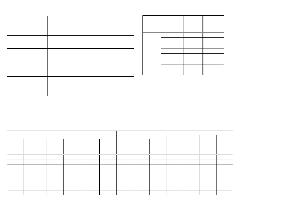
10. Specications
Input:AC100~240V 50/60Hz
Output:DC15V 1A
Dimensions 55(W) × 205(D) × 143(H) (mm)
Weight Approx. 2.4Kg (including rail)
Screw capacity Approx. 40cc
Following
accessories
Operation Manual 1 copy
AC Adapter 1 unit
Hexagonal Wrench 1 piece
Screwdriver 1 piece
Ground wire 1 piece
Installation location Level stable place
Installation and
storage condition
Temperature 0 ~ 40 ℃
Humidity 10 to 85% (without condensation)
Compliance standards
EMC: 2014/30/EU
RoHS: 2011/65/EU
Power
AC adapter
(switching type)
Reference table of the specified screws
Screw
size
Screw shaft
diameter(φ )
Screw
head
diameter
(φ )
Washer
diameter
(φ )
Screw
head
thickness
(mm)
Screw
shaft
length
(mm)
Sems
Double
sems
Washer
head
Shape of screw head
Pan head
Bind
Truss
Precision
screw
hexagon
flange
bolt
Reference table of the specified screws
Screw
feeder
series
Screw feeder
model
Screw size
Rail model
No.
Screw
size
Screw shaft
diameter(φ )
Screw
head
diameter
(φ )
Washer
diameter
(φ )
Screw
head
thickness
(mm)
Screw
shaft
length
(mm)
Sems
Double
sems
Washer
head
SS-1210 φ 1.0 WR10 φ 1.0 0.9~0.95 1.2~2.0 - 0.35~1.0 1.6~10 ○
SS-1212 φ 1.2 WR12 φ 1.2 1.1~1.15 1.4~2.3 - 0.35~1.0 1.8~10 ○
SS-1214 φ 1.4 WR14 φ 1.4 1.3~1.4 1.7~2.5 - 0.35~1.0 2.0~10 ○
SS-1217 φ 1.7 WR17 φ 1.7 1.6~1.7 2.0~3.0 - 0.35~1.0 2.3~10 ○
SS-1220 φ 2.0 WR20 φ 2.0 1.9~2.1 2.4~4.0 2.4~6.0 0.35 ~1.3 2.6~16 ○ ○ ○ ○ ○ ○ ○
SS-2323 φ 2.3 WR23 φ 2.3 2.2~2.4 2.7~4.0 2.7~7.0 0.35 ~1.5 2.9~16 ○ ○ ○ ○ ○ ○ ○
SS-2326 φ 2.6 WR26 φ 2.6 2.5~2.7 3.0~4.5 3.0~7.5 0.35 ~1.7 3.2~16 ○ ○ ○ ○ ○ ○ ○
SS-2330 φ 3.0 WR30 φ 3.0 2.9~3.2 3.5~5.5 3.5~8.0 0.35 ~2.0 3.6~16 ○ ○ ○ ○ ○ ○ ○
SS-12
SS-23
Shape of screw head
Pan head
Bind
Truss
Precision
screw
hexagon
flange
bolt
Note) Compatible with washer thickness 0.35 to 1.0 mm.
Note:
● Check that the screw diameter matches the rail groove width.
● Within The range of screw size and length below,there may be instances of
unique screw shape or structure not compatible with the feeder unit.
● When changing the rail, check that the rail number matches the model number
of the model you are using.
● Interchangeable rails are optional.
● The design, features and specications of the machine may be modied without
prior notice to improve quality.
● Noise is less than LAeq70 dB. (1 m distance.)
● Complies with EC compliance standards.
Page 30
- 29 -
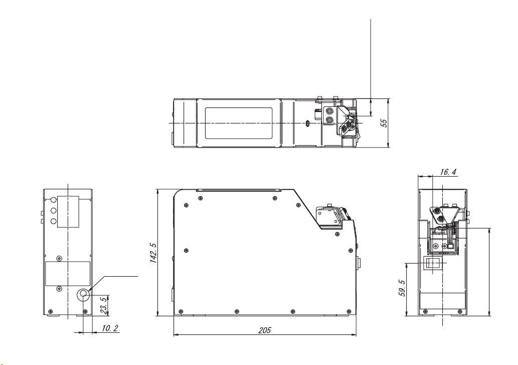
11. External Dimensions
DC jack
19.7(pick-up position)
98.8(Pick-up position)
Unit:mm
Page 31

- 30 -
12. Warranty
For users within Japan, the effective term of warranty is 6 months after delivery.
Such warranty will not be applicable to purchases or users outside of Japan.
If any troubles should occur, please contact your dealer.
After the warranty period, repair services will be completed.
In the following cases, the purchaser shall pay for parts and labor regardless of the terms of
warranty:
②
③
④
⑤
and replaceable parts and replacement work expenses.
The repair parts shall be available within 5 years after purchase.
Failure due to improper handling.
①
Failure due to product modication or improper processing.
Failure due to causes beyond control (for example earthquake or re).
Failure attributable to any cause other than this product.
Consumables (brushes,
driving belt,
main motor
)
Page 32

- 31 -
「Quicher」 「OHTAKE」 「OHTAKE ・ ROOT KOGYO」 are trademarks or/and registered trademarks of OHTAKE ・ ROOT KOGYO CO.LTD.]
「Quicher( クイッチャー)」 「OHTAKE」 「OHTAKE ・ ROOT KOGYO」 は、 株式会社 大武 ・ ルート工業の商標又は登録商標です。
The specifications and/or design may be altered, without notice, whenever there are changes or improvements.
改良のため、 予告なくデザイン、 性能、 仕様等を変更することがあります。
Photocopying, reproduction or publication, in whole or in part, of this manual, without permission, is strictly prohibited by copyright law.
この取扱説明書の一部または全部の無断転載、 複製を禁じます。
© Copyright OHTAKE ・ ROOT KOGYO CO.,LTD.
岩手県一関市萩荘字金ヶ崎
27 〒021-0902
Tel 0191-24-3144
Fax 0191-24-3145
27 Kangasaki Hagisyou
Ichinoseki
Iwate, 021-0902 JAPAN
Tel +81-191-24-3144
Fax +81-191-24-3145
http://www.ohtake-root.co.jp
(as of November, 2014)
(2014 年 11 月現在 )
27 Kanegasaki Hagisho Ichinoseki
Iwate, 021-0902 JAPAN
Tel +81-191-24-3144
Fax +81-191-24-3145
岩手県一関市萩荘字金ヶ崎27〒
021-0902
Tel +81-191-24-3144
Fax +81-191-24-3145
(as of Apr. 2019)
(2019 年 4 月現在 )
 Loading...