

OHTAKE NSB2, NSB2-10, NSB2-12, NSB2-14, NSB2-17 Operation Manual
...
16,50$(
4GCFVJGUGKPUVTWEVKQPUHQTVJGRTQRGTWUGQHVJKUOCEJKPG
#HVGTJCXKPITGCFVJGUGKPUVTWEVKQPUMGGRVJGOKPCEQPXGPKGPVRNCEGUQ[QW
QTVJGQRGTCVQTECPTGHGTVQVJGOYJGPGXGTPGEGUUCT[
䠪䠯䠮䠥㻌㼀㼥㼜㼑
$XWRPDWLF6FUHZ)HHGHU
ὀព㸟㸸www.ohtake-root.co.jp ࡀᙜ♫၏୍ࡢ HP ࢻࣞࢫ࡛ࡍࠋ
ᘢ♫ࡢྡࢆ㦄ࡿഇࢧࢺࡈὀពୗࡉ࠸ࠋ⌧ᅾࠊᙜ♫ࡣ୰ᅜᅜෆᨭᗑࡣࡈࡊ࠸ࡲࡏࢇࠋ
ྛ栦ᐈ実ὀព㸸ࠕwww.ohtake-root.co.jp ᩎྖ၏୍ⓗᐁ᪉⨒❰㸪
┠๓㸪ᩎྖᅾ୰ᅜἐ᭷≆⢬ᡤ宻ⓗ୰ᅜᐁ⨒ࠋࠖ
ATTENTION : www.ohtake-root.co.jp is the only web site associated with our company.
We do not have any branches in China.
Operation Manual
Read these instructions for the proper use of this machine.
After having read these instructions,
keep them in a convenient place so you
or the operator can refer to them whenever necessary.
自動ネジ供給機
NSB²
Series
Automatic Screw Feeder
NSB2MA01
Ma
(Maintenance)

-1-
CONTENTS
1. BEFORE USE
・・・・・・・・・・・・・・・・・・・・・・・・・・・・・・・・・・
1
2. FOR SAFE USE
・・・・・・・・・・・・・・・・・・・・・・・・・・・・・・・・・・
2
3. NAME OF MACHINE PARTS
・・・・・・・・・・・・・・・・・・・・・・・・・・・・・・・・
3
4. ADJUSTMENTS AND CHECKS BEFORE USE
・・・・・・・・・・・・・・・・
4
5. OPERATING INSTRUCTIONS
・・・・・・・・・・・・・・・・・・・・・・・・・・・・・・・
12
6. REPLACEMENT OF CONSUMABLE PARTS
・・・・・・・・・・・・・・・・・
13
7. OTHERS
・・・・・・・・・・・・・・・・・・・・・・・・・・・・・・・・・・
18
8. TROUBLESHOOTING
・・・・・・・・・・・・・・・・・・・・・・・・・・・・・・・・・・
18
9. SPECIFICATIONS
・・・・・・・・・・・・・・・・・・・・・・・・・・・・・・・・・・
23
10. EXTERNAL DIMENSIONS
・・・・・・・・・・・・・・・・・・・・・・・・・・・・・・・・・・
25
11. WARRANTY
・・・・・・・・・・・・・・・・・・・・・・・・・・・・・・・・・・
26
Cautions
Be sure to follow the cautions, or it could lead to serious damage, such as injuries.
electric shock, and damage to properties.
1)
BEFORE USE
Thank you very much for selecting our Automatic Screw Feeder “NSB² series”. Please check the following accessories before
operating the machine.
*
Instruction manual, 1 copy
*
Passage plate, 2 pieces (1 piece is already attached to the main body.)
*
AC adapter, 1 piece
*
0.35 mm gauge plate, 1 piece (used for adjusting the holding plate)
*
Hexagonal wrench, 1 piece
*
Screwdriver, 1 piece

-2-
2)
FOR SAFE USE
Read the following Cautions thoroughly for the safe use of this machine. Keep them in mind during the operation
of the machine in order to prevent injuries and damage to property.
- Installation
Caution:
Install the machine on a level, stable location that can endure it’s weight and running conditions.
If the machine falls down or turns over due to improper installation, injuries or property damage may occur.
- Operating Environment
Caution:
Do not operate this machine where ammable or corrosive gas is present. It is extremely dangerous
to use this machine under such circumstances. Do not operate this machine in environment of high humidity.
- AC adapter
Caution:
Use only the AC adapter supplied with this machine otherwise it may result in a re or electric shock.
- Rail
Caution:
Do not damage nor oil the rail.
- Screw compatibility
Caution:
Do not use screws with grease, dirty screws or any screw other than those prescribed.
- Access of screws
Caution:
Do not exert excessive or impactive force when accessing the screws.
- When machine is not in use
Caution:
Be sure to unplug the AC adapter from the wall outlet during closing hours and if the machine will be
left unattended for any extended period of time.
- Abnormalities during operation
Caution:
Stop operation and unplug immediately whenever you sense abnormalities or unusual machine
behaviors during the operation of this machine, such as a pungent odor. Turn off the power switch and
disconnect the AC adapter from the receptacle. Continued operation may cause re, electric shock,
malfunction or personal injury. Immediately contact the dealer from which you purchased the product.
- Servicing
Caution:
Do not attempt to repair, disassemble or modify this machine except where specied by this manual.
Consult your dealer for service and repair of this machine.
-3-
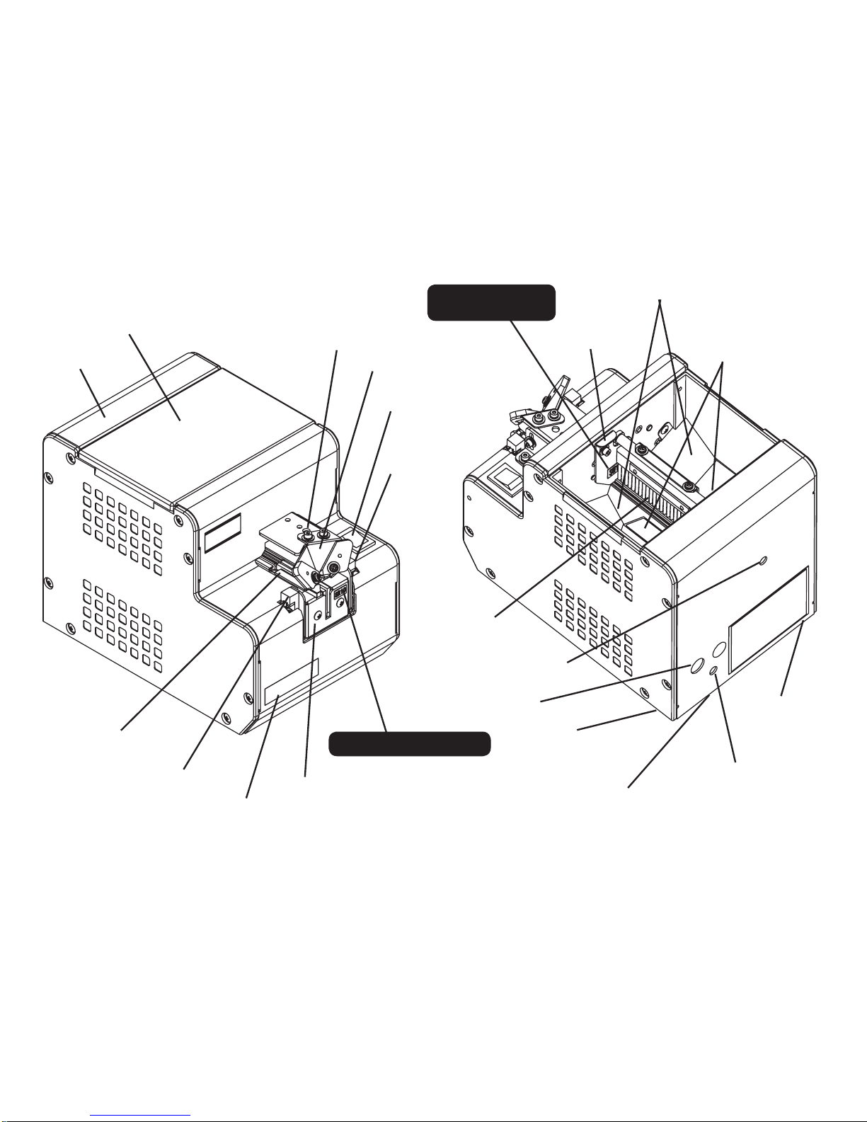
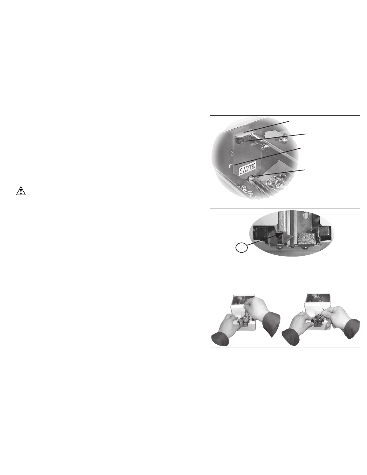
3) NAMES OF MACHINE PARTS
Upper cover
Rear cover
Rail xing bolt
Power swtich
Holding plate
Light-receiving
sensor
Light-emitting
sensor
Bit guide
Front cover
Rail assembly
Timer knob
Brush
Passing plate
Passing plate
identication seal
Scooping block
(left and right)
(moving up and down)
Scooping chamber
Rail identication seal
Tilting bolt(under
the machine
)
Vibr a tion adjus t ing
plate xing bolt
DC jack
Tilting bolt(under
the machine
)
Vibration adjusting bolt
(under the machine
)
-4-
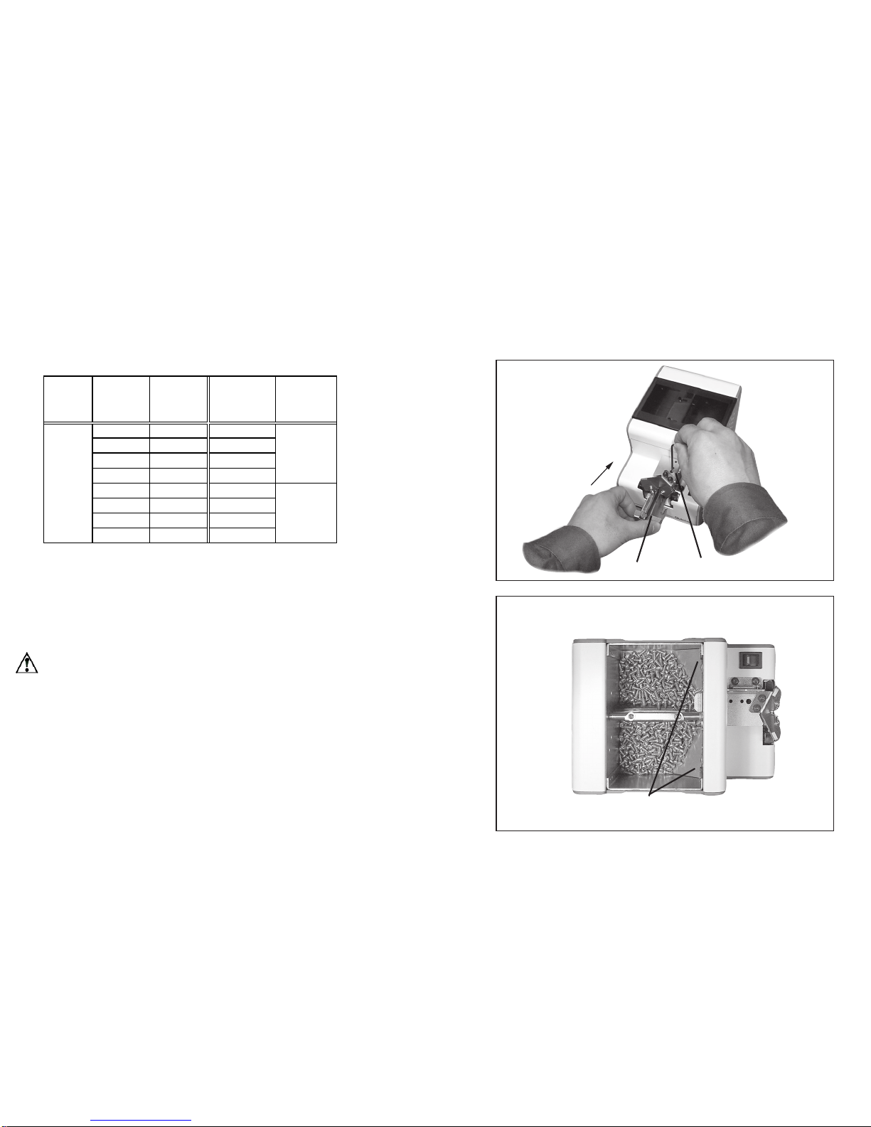
◆ When there is no rail installed on the machine, please install the rail
before use.
- First, unfasten the rail xing bolt through the upper bit guide holder
- Insert the rail into the furthest point
- Fasten the xing bolt
Quantity of screws thrown in
If too many screws are thrown in, orientation and transfer of the
screws will be seriously affected.See the diagram on the right for the
maximum number of throw screws in the [scooping chanber].
* Set the [scooping block] in the lowest possible position.
* Throw in screws up to a position of 2 mm to 3 mm below the rail
groove face.
* In this condition, ensure that the front inclined-face of the ramp is
not hidden by the screws.
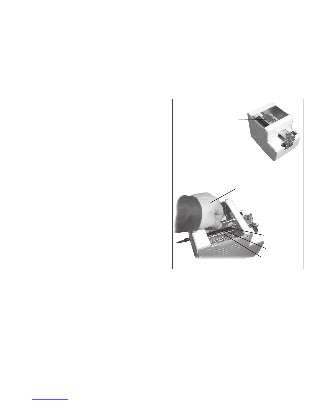
4)
ADJUSTMENTS AND CHECKS BEFORE USE
Before using the machine, please check if the rail and components installed on the machine is suitable for the screw applied. The rail is φ1.0 to φ3.0 depending on the nominal diameter. It is determined by the identication seal on a rail
front cover. There are two kinds of passage plates, namely one for φ1.0 to φ1.7 and one for φ2.0 to φ3.0. It is deter-
mined by a identication seal afxed on a passage plate.
These parts of the inclined face of the ramp should
be
use underline.
Ensure that the rail groove face is not hidden by the screws.
(Screws should be positioned 2 to 3 mm below the rail
groove.)
Rail xing boltRail
Reference table of the specified screws
Screw
feeder
series
Screw
feeder
model
Screw size Rail model No.
Passing plate
model No.
Screw
size
Screw shaft
diameter(φ )
Screw
head
diameter
(φ )
Screw
head
thickness
(mm)
Screw
shaft
length
(mm)
Sems
Double
sems
Washer
head
NSB²-10
φ 1.0 SR10 φ 1.0 0.9~0.95 1.2~4.5 0.35~1.0 1.6~10 ○
NSB²-12
φ 1.2 SR12 φ 1.2 1.1~1.15 1.4~4.5 0.35~1.0 1.8~10 ○
NSB²-14
φ 1.4 SR14 φ 1.4 1.3~1.4 1.7~4.5 0.35~1.0 2.0~10 ○
NSB²-17
φ 1.7 SR17 φ 1.7 1.6~1.7 2.0~4.5 0.35~1.0 2.3~10 ○
NSB²-20
φ 2.0 SR20 φ 2.0 1.9~2.1 2.4~6 0.35~4.5 2.6~20 ○ ○ ○ ○ ○ ○ ○
NSB²-23
φ 2.3 SR23 φ 2.3 2.2~2.4 2.7~6 0.35~4.5 2.9~20 ○ ○ ○ ○ ○ ○ ○
NSB²-26
φ 2.6 SR26 φ 2.6 2.5~2.7 3.0~6 0.35~4.5 3.2~20 ○ ○ ○ ○ ○ ○ ○
NSB²-30
φ 3.0 SR30 φ 3.0 2.9~3.2 3.5~6 0.35~4.5 3.6~20 ○ ○ ○ ○ ○ ○ ○
NSB²
SW1017
SW2030
Shape of screw head
Pan head
bind
Flat head
Counter
sunk
head
hexagon
flange
bolt
-5-
◆
Adjustment of the brush
Check the height of the brush.
* As in the picture on the right, set the brush to an approximately level position.
* Ensure that the edge of the brush is grazing the screw’s
head.
* If the height of the brush is either too low or too high, orientation and transfer of the screws will be seriously affected.
* If adjustment is necessary, adjust it by loosening the brush
height adjusting screw.
Note:
Always unplug the AC adapter from the wall outlet be-
fore making any adjustments to avoid injury.
Turn the power switch on & off,
and set the brush on the level.
Ensure that the edge of the
brush is grazing the screw’s
head.
Adjustment screw
for the brush
Brush
Screws
-6-
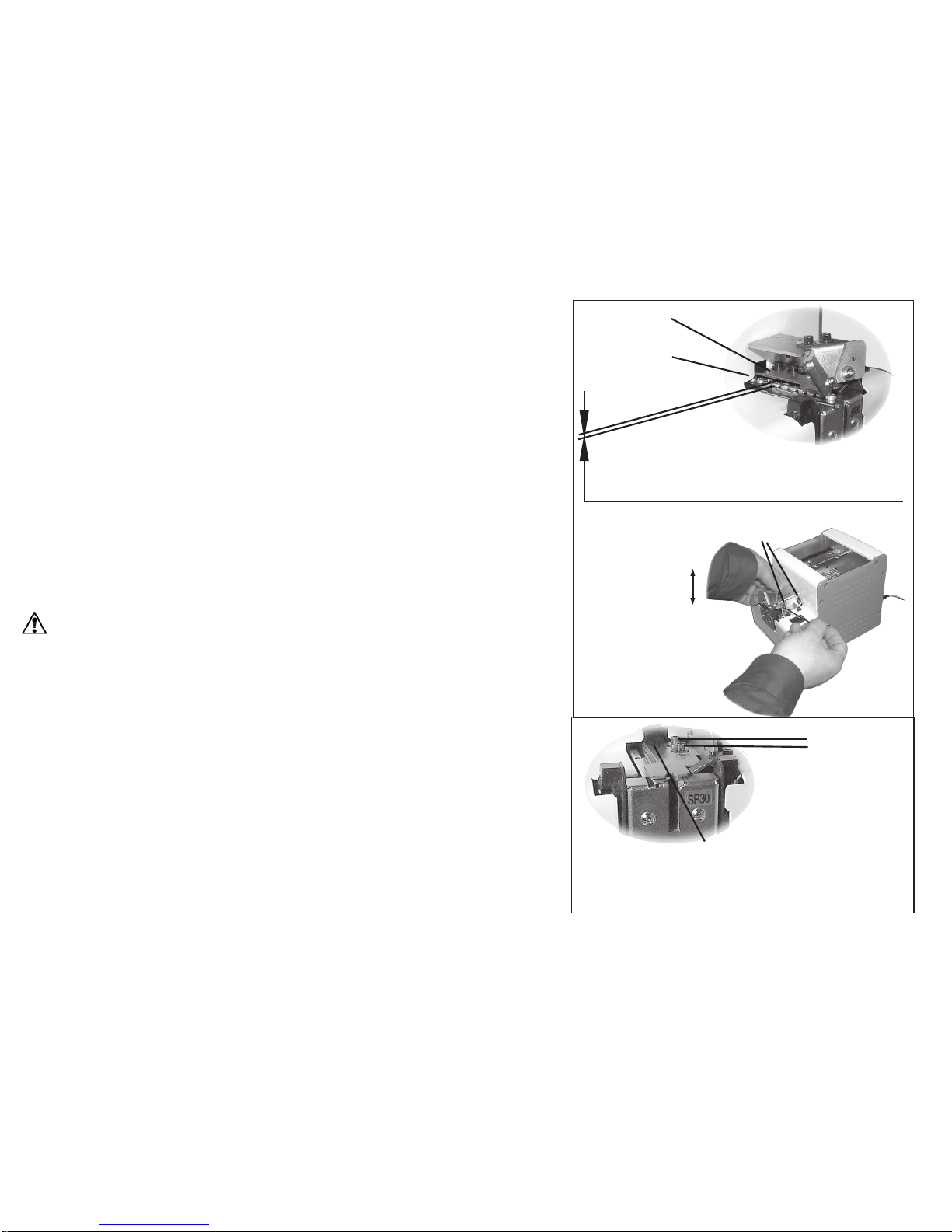
◆
Adjustment of the holding plate
Check the position of the holding plate.
* Ensure that the gap between the head of the used screw in the rail
groove and the holding plate is approximately 0.2 mm to 1 mm.
* If there is no gap, the screw gets caught. If the gap is too large, the
screw overlaps or juts out.
* If adjustment is necessary, adjust it up or down by loosening the bit
guide bracket attaching screw.
◆
Easily adjust it by using the 0.35 mm gauge plate.
* Loosen the bit guide bracket attaching screw. Insert the gauge between screws on the rail and the holding plate. Tighten the bit guide
bracket attaching screw when the holding plate is touching the front and
the back of the gauge equally.
Caution:
Matching the center of the holding plate outlet and the rail
center may be necessary.
* Ensure that the center of the holding plate outlet matches the rail center.
* If not, adjust it by loosening the attaching screw.
Holding plate
Screws
The bit guide bracket attaching screws
Adjustment of
the height
The gap between the holding plate and the head
of screws should be 0 .2 mm to 1 mm. The
holding plate and the rail should be parallel,too.
Match the center of the holding
plate outlet and the rail.
(It’s not necessary to remove the
bit guide.)
Attaching
screws
-7-
◆
Adjustment of the passage plate
Check the height of the passage plate.
* Ensure that the passage plate is adjusted at a height where the
used screw can manage to pass.
* If the passage plate is too low, the screw cannot pass, and if too
high, the screw easily gets caught.
* If adjustment is necessary, adjust it by loosening the passage
plate attaching screw.
Caution:
Slide the half blankings at both sides of the passage
plate up and down the guide.
◆
Adjustment of the rail
Check the physical relationship of the stopper and sensor.
* Ensure that the rail is xed so that “A” portion of the stopper is 0
mm to 0.5 mm ahead of the sensor optical axis.
* If adjustment is necessary, adjust it’s location by loosening the
rail attaching screw.
Halfway hole
(On both sides of the
passage plate)
Ensure the screw passes
through the window with no
extra space.
Screw
Passage plate
Passage plate
attaching screw
Looking down from the top, a portion of the stopper is
sticking out 0 to 0.5 mm more forward than the sensor’s
optical axis. (It’s necessary to remove the bit guide.)
A
Loosen the rail
attaching screw.
Adjust the rail back and
forth.
-8-
◆
Check/adjustment of the bit guide
Check the position of the bit guide.
* Adjust the bit guide to a position where a user can easily take
screws.
Actually pick up screws a few times to adjust it.
Adjust it by loosening the attaching screws.
Caution:
The rail is adjusted according to the physical relationship with the sensor as on the preceding page, so basically
the rail is not adjusted here.
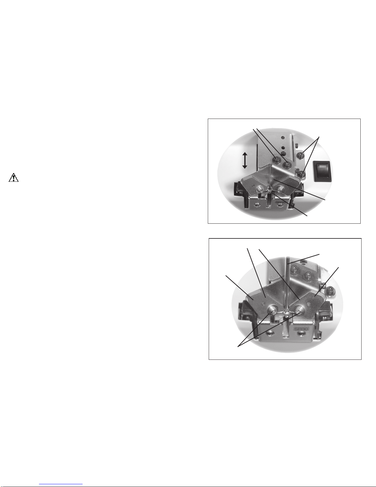
◆
Adjustment of the left and right guide pieces
Please check and adjust position of the guide piece as necessary.
The bit guide is originally set at approximately 3mm at the front
opening, and shall be adjusted as needed by the user.
- Unfasten the front xing screws, insert driver-bit to be used and
adjust the slit opening, so that the bit can move freely.
- After the adjustment, try to pick up a screw and check its working
condition before turning on the power.
Guide attaching screws
Right guide plate
Left guide plate
Driver bit
Adjust the guide plate
The bit guide attaching screws
(Assy. attachiing
screws)
Adjustment
Bit guide
Screw
 Loading...