

Page 1

16,50$(
4GCFVJGUGKPUVTWEVKQPUHQTVJGRTQRGTWUGQHVJKUOCEJKPG
#HVGTJCXKPITGCFVJGUGKPUVTWEVKQPUMGGRVJGOKPCEQPXGPKGPVRNCEGUQ[QW
QTVJGQRGTCVQTECPTGHGTVQVJGOYJGPGXGTPGEGUUCT[
䠪䠯䠮䠥㻌㼀㼥㼜㼑
$XWRPDWLF6FUHZ)HHGHU
ὀព㸟㸸www.ohtake-root.co.jp ࡀᙜ♫၏୍ࡢ HP ࢻࣞࢫ࡛ࡍࠋ
ᘢ♫ࡢྡࢆ㦄ࡿഇࢧࢺࡈὀពୗࡉ࠸ࠋ⌧ᅾࠊᙜ♫ࡣ୰ᅜᅜෆᨭᗑࡣࡈࡊ࠸ࡲࡏࢇࠋ
ྛ栦ᐈ実ὀព㸸ࠕwww.ohtake-root.co.jp ᩎྖ၏୍ⓗᐁ᪉⨒❰㸪
┠๓㸪ᩎྖᅾ୰ᅜἐ᭷≆⢬ᡤ宻ⓗ୰ᅜᐁ⨒ࠋࠖ
ATTENTION : www.ohtake-root.co.jp is the only web site associated with our company.
We do not have any branches in China.
Operation Manual
Read these instructions for the proper use of this machine.
After having read these instructions,
keep them in a convenient place so you
or the operator can refer to them whenever necessary.
自動ネジ供給機
NSB²
Series
Automatic Screw Feeder
NSB2MA01
Ma
(Maintenance)
Page 2
-1-
CONTENTS
1. BEFORE USE
・・・・・・・・・・・・・・・・・・・・・・・・・・・・・・・・・・
1
2. FOR SAFE USE
・・・・・・・・・・・・・・・・・・・・・・・・・・・・・・・・・・
2
3. NAME OF MACHINE PARTS
・・・・・・・・・・・・・・・・・・・・・・・・・・・・・・・・
3
4. ADJUSTMENTS AND CHECKS BEFORE USE
・・・・・・・・・・・・・・・・
4
5. OPERATING INSTRUCTIONS
・・・・・・・・・・・・・・・・・・・・・・・・・・・・・・・
12
6. REPLACEMENT OF CONSUMABLE PARTS
・・・・・・・・・・・・・・・・・
13
7. OTHERS
・・・・・・・・・・・・・・・・・・・・・・・・・・・・・・・・・・
18
8. TROUBLESHOOTING
・・・・・・・・・・・・・・・・・・・・・・・・・・・・・・・・・・
18
9. SPECIFICATIONS
・・・・・・・・・・・・・・・・・・・・・・・・・・・・・・・・・・
23
10. EXTERNAL DIMENSIONS
・・・・・・・・・・・・・・・・・・・・・・・・・・・・・・・・・・
25
11. WARRANTY
・・・・・・・・・・・・・・・・・・・・・・・・・・・・・・・・・・
26
Cautions
Be sure to follow the cautions, or it could lead to serious damage, such as injuries.
electric shock, and damage to properties.
1)
BEFORE USE
Thank you very much for selecting our Automatic Screw Feeder “NSB² series”. Please check the following accessories before
operating the machine.
*
Instruction manual, 1 copy
*
Passage plate, 2 pieces (1 piece is already attached to the main body.)
*
AC adapter, 1 piece
*
0.35 mm gauge plate, 1 piece (used for adjusting the holding plate)
*
Hexagonal wrench, 1 piece
*
Screwdriver, 1 piece
Page 3
-2-
2)
FOR SAFE USE
Read the following Cautions thoroughly for the safe use of this machine. Keep them in mind during the operation
of the machine in order to prevent injuries and damage to property.
- Installation
Caution:
Install the machine on a level, stable location that can endure it’s weight and running conditions.
If the machine falls down or turns over due to improper installation, injuries or property damage may occur.
- Operating Environment
Caution:
Do not operate this machine where ammable or corrosive gas is present. It is extremely dangerous
to use this machine under such circumstances. Do not operate this machine in environment of high humidity.
- AC adapter
Caution:
Use only the AC adapter supplied with this machine otherwise it may result in a re or electric shock.
- Rail
Caution:
Do not damage nor oil the rail.
- Screw compatibility
Caution:
Do not use screws with grease, dirty screws or any screw other than those prescribed.
- Access of screws
Caution:
Do not exert excessive or impactive force when accessing the screws.
- When machine is not in use
Caution:
Be sure to unplug the AC adapter from the wall outlet during closing hours and if the machine will be
left unattended for any extended period of time.
- Abnormalities during operation
Caution:
Stop operation and unplug immediately whenever you sense abnormalities or unusual machine
behaviors during the operation of this machine, such as a pungent odor. Turn off the power switch and
disconnect the AC adapter from the receptacle. Continued operation may cause re, electric shock,
malfunction or personal injury. Immediately contact the dealer from which you purchased the product.
- Servicing
Caution:
Do not attempt to repair, disassemble or modify this machine except where specied by this manual.
Consult your dealer for service and repair of this machine.
Page 4
-3-
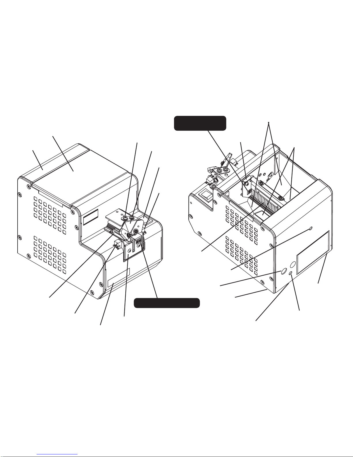
3) NAMES OF MACHINE PARTS
Upper cover
Rear cover
Rail xing bolt
Power swtich
Holding plate
Light-receiving
sensor
Light-emitting
sensor
Bit guide
Front cover
Rail assembly
Timer knob
Brush
Passing plate
Passing plate
identication seal
Scooping block
(left and right)
(moving up and down)
Scooping chamber
Rail identication seal
Tilting bolt(under
the machine
)
Vibr a tion adjus t ing
plate xing bolt
DC jack
Tilting bolt(under
the machine
)
Vibration adjusting bolt
(under the machine
)
Page 5
-4-
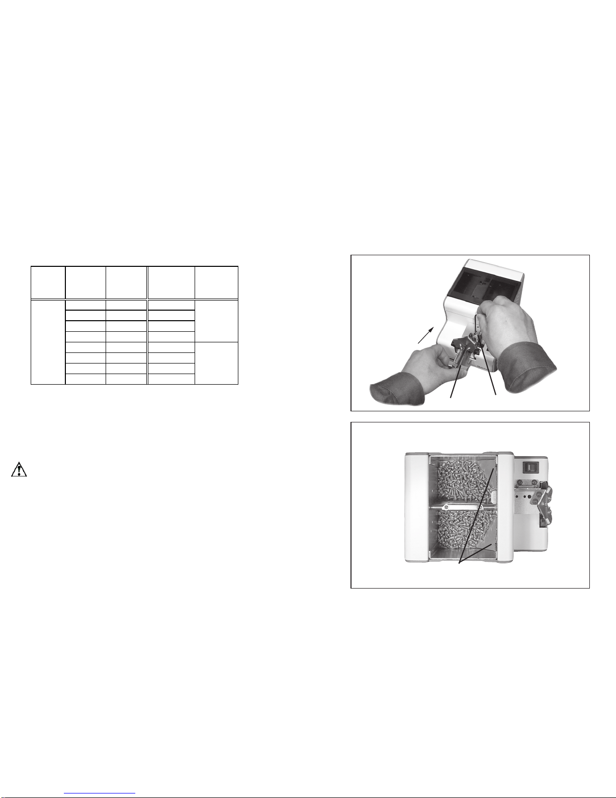
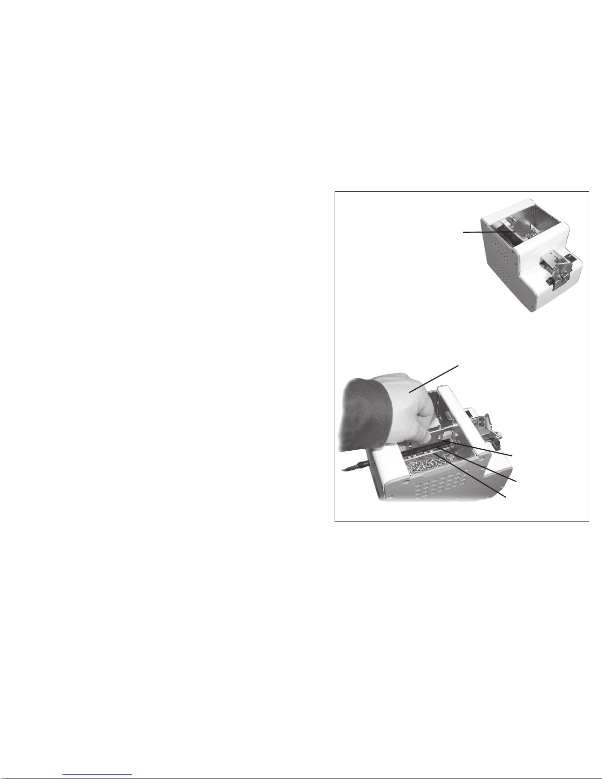
◆ When there is no rail installed on the machine, please install the rail
before use.
- First, unfasten the rail xing bolt through the upper bit guide holder
- Insert the rail into the furthest point
- Fasten the xing bolt
Quantity of screws thrown in
If too many screws are thrown in, orientation and transfer of the
screws will be seriously affected.See the diagram on the right for the
maximum number of throw screws in the [scooping chanber].
* Set the [scooping block] in the lowest possible position.
* Throw in screws up to a position of 2 mm to 3 mm below the rail
groove face.
* In this condition, ensure that the front inclined-face of the ramp is
not hidden by the screws.
4)
ADJUSTMENTS AND CHECKS BEFORE USE
Before using the machine, please check if the rail and components installed on the machine is suitable for the screw applied. The rail is φ1.0 to φ3.0 depending on the nominal diameter. It is determined by the identication seal on a rail
front cover. There are two kinds of passage plates, namely one for φ1.0 to φ1.7 and one for φ2.0 to φ3.0. It is deter-
mined by a identication seal afxed on a passage plate.
These parts of the inclined face of the ramp should
be
use underline.
Ensure that the rail groove face is not hidden by the screws.
(Screws should be positioned 2 to 3 mm below the rail
groove.)
Rail xing boltRail
Reference table of the specified screws
Screw
feeder
series
Screw
feeder
model
Screw size Rail model No.
Passing plate
model No.
Screw
size
Screw shaft
diameter(φ )
Screw
head
diameter
(φ )
Screw
head
thickness
(mm)
Screw
shaft
length
(mm)
Sems
Double
sems
Washer
head
NSB²-10
φ 1.0 SR10 φ 1.0 0.9~0.95 1.2~4.5 0.35~1.0 1.6~10 ○
NSB²-12
φ 1.2 SR12 φ 1.2 1.1~1.15 1.4~4.5 0.35~1.0 1.8~10 ○
NSB²-14
φ 1.4 SR14 φ 1.4 1.3~1.4 1.7~4.5 0.35~1.0 2.0~10 ○
NSB²-17
φ 1.7 SR17 φ 1.7 1.6~1.7 2.0~4.5 0.35~1.0 2.3~10 ○
NSB²-20
φ 2.0 SR20 φ 2.0 1.9~2.1 2.4~6 0.35~4.5 2.6~20 ○ ○ ○ ○ ○ ○ ○
NSB²-23
φ 2.3 SR23 φ 2.3 2.2~2.4 2.7~6 0.35~4.5 2.9~20 ○ ○ ○ ○ ○ ○ ○
NSB²-26
φ 2.6 SR26 φ 2.6 2.5~2.7 3.0~6 0.35~4.5 3.2~20 ○ ○ ○ ○ ○ ○ ○
NSB²-30
φ 3.0 SR30 φ 3.0 2.9~3.2 3.5~6 0.35~4.5 3.6~20 ○ ○ ○ ○ ○ ○ ○
NSB²
SW1017
SW2030
Shape of screw head
Pan head
bind
Flat head
Counter
sunk
head
hexagon
flange
bolt
Page 6
-5-
◆
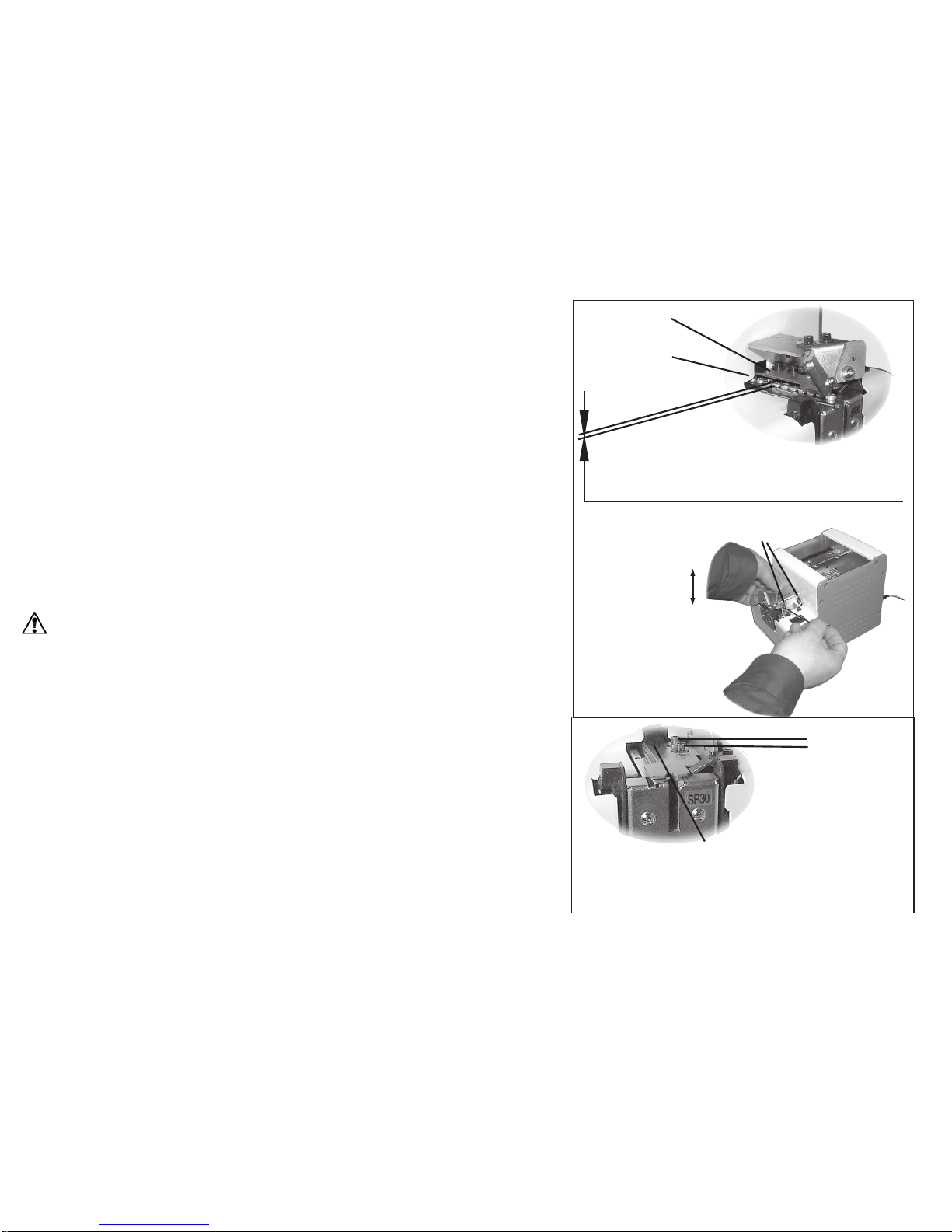
Adjustment of the brush
Check the height of the brush.
* As in the picture on the right, set the brush to an approximately level position.
* Ensure that the edge of the brush is grazing the screw’s
head.
* If the height of the brush is either too low or too high, orientation and transfer of the screws will be seriously affected.
* If adjustment is necessary, adjust it by loosening the brush
height adjusting screw.
Note:
Always unplug the AC adapter from the wall outlet be-
fore making any adjustments to avoid injury.
Turn the power switch on & off,
and set the brush on the level.
Ensure that the edge of the
brush is grazing the screw’s
head.
Adjustment screw
for the brush
Brush
Screws
Page 7
-6-
◆
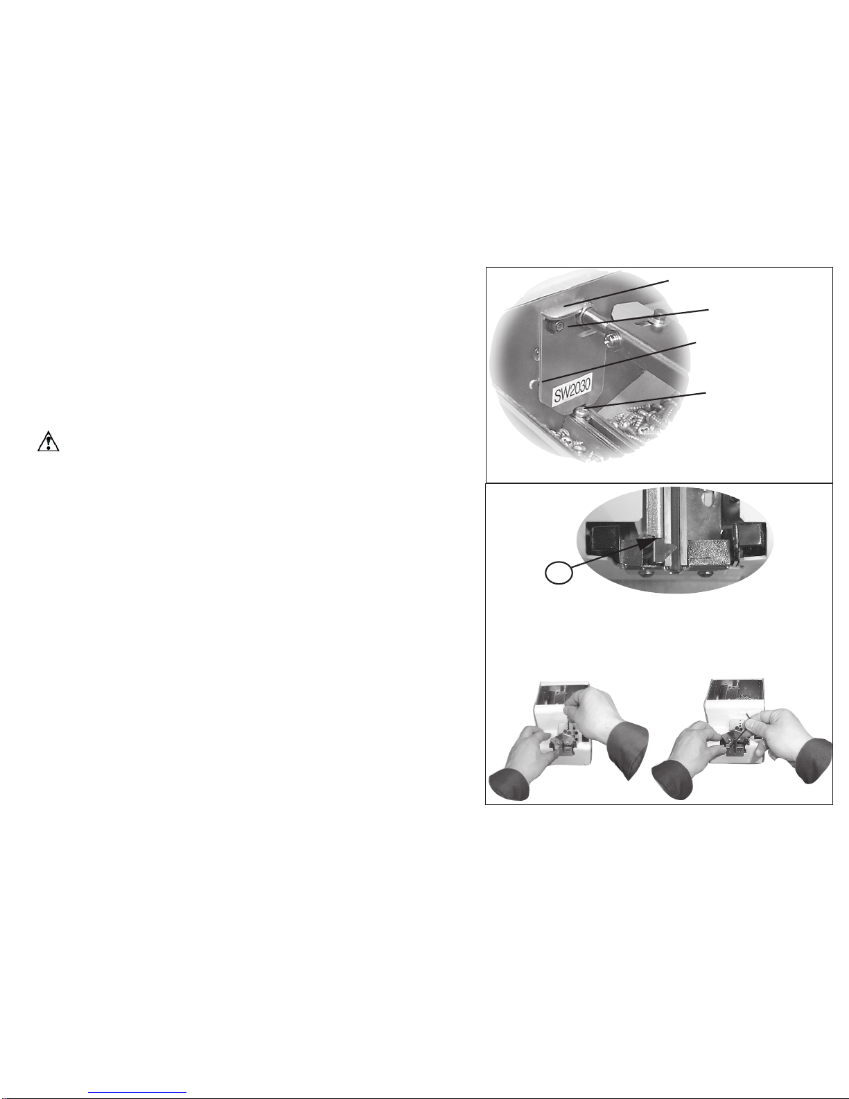
Adjustment of the holding plate
Check the position of the holding plate.
* Ensure that the gap between the head of the used screw in the rail
groove and the holding plate is approximately 0.2 mm to 1 mm.
* If there is no gap, the screw gets caught. If the gap is too large, the
screw overlaps or juts out.
* If adjustment is necessary, adjust it up or down by loosening the bit
guide bracket attaching screw.
◆
Easily adjust it by using the 0.35 mm gauge plate.
* Loosen the bit guide bracket attaching screw. Insert the gauge between screws on the rail and the holding plate. Tighten the bit guide
bracket attaching screw when the holding plate is touching the front and
the back of the gauge equally.
Caution:
Matching the center of the holding plate outlet and the rail
center may be necessary.
* Ensure that the center of the holding plate outlet matches the rail center.
* If not, adjust it by loosening the attaching screw.
Holding plate
Screws
The bit guide bracket attaching screws
Adjustment of
the height
The gap between the holding plate and the head
of screws should be 0 .2 mm to 1 mm. The
holding plate and the rail should be parallel,too.
Match the center of the holding
plate outlet and the rail.
(It’s not necessary to remove the
bit guide.)
Attaching
screws
Page 8
-7-
◆
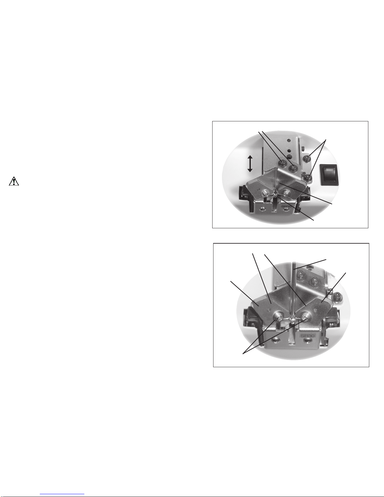
Adjustment of the passage plate
Check the height of the passage plate.
* Ensure that the passage plate is adjusted at a height where the
used screw can manage to pass.
* If the passage plate is too low, the screw cannot pass, and if too
high, the screw easily gets caught.
* If adjustment is necessary, adjust it by loosening the passage
plate attaching screw.
Caution:
Slide the half blankings at both sides of the passage
plate up and down the guide.
◆
Adjustment of the rail
Check the physical relationship of the stopper and sensor.
* Ensure that the rail is xed so that “A” portion of the stopper is 0
mm to 0.5 mm ahead of the sensor optical axis.
* If adjustment is necessary, adjust it’s location by loosening the
rail attaching screw.
Halfway hole
(On both sides of the
passage plate)
Ensure the screw passes
through the window with no
extra space.
Screw
Passage plate
Passage plate
attaching screw
Looking down from the top, a portion of the stopper is
sticking out 0 to 0.5 mm more forward than the sensor’s
optical axis. (It’s necessary to remove the bit guide.)
A
Loosen the rail
attaching screw.
Adjust the rail back and
forth.
Page 9
-8-
◆
Check/adjustment of the bit guide
Check the position of the bit guide.
* Adjust the bit guide to a position where a user can easily take
screws.
Actually pick up screws a few times to adjust it.
Adjust it by loosening the attaching screws.
Caution:
The rail is adjusted according to the physical relationship with the sensor as on the preceding page, so basically
the rail is not adjusted here.
◆
Adjustment of the left and right guide pieces
Please check and adjust position of the guide piece as necessary.
The bit guide is originally set at approximately 3mm at the front
opening, and shall be adjusted as needed by the user.
- Unfasten the front xing screws, insert driver-bit to be used and
adjust the slit opening, so that the bit can move freely.
- After the adjustment, try to pick up a screw and check its working
condition before turning on the power.
Guide attaching screws
Right guide plate
Left guide plate
Driver bit
Adjust the guide plate
The bit guide attaching screws
(Assy. attachiing
screws)
Adjustment
Bit guide
Screw
Page 10
-9-
◆
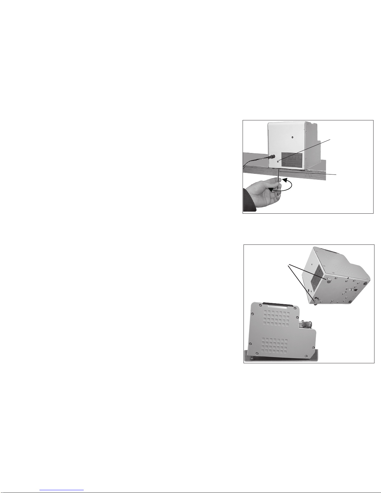
Adjustment of the tilting bolts
- As the original setting, the automatic screw feeder shall be horizontal
when set on a surface.
Depending on specific type of screw applied, there may be cases that
the screws cannot move smoothly. At such instance, please check the
“Adjustment of the rail” section listed in this operation booklet, or adjust
tilting angle of the machine as necessary:
- The tilting bolts are located on bottom rear end of the machine.
- When these bolts are used, they shall be set at the same height and angle
on both sides.
- Since the bolts do not have stoppers equipped inside, please be careful
not to detach them from the machine body.
- After the adjustment, please verify if screw delivery functions properly
before application.
◆
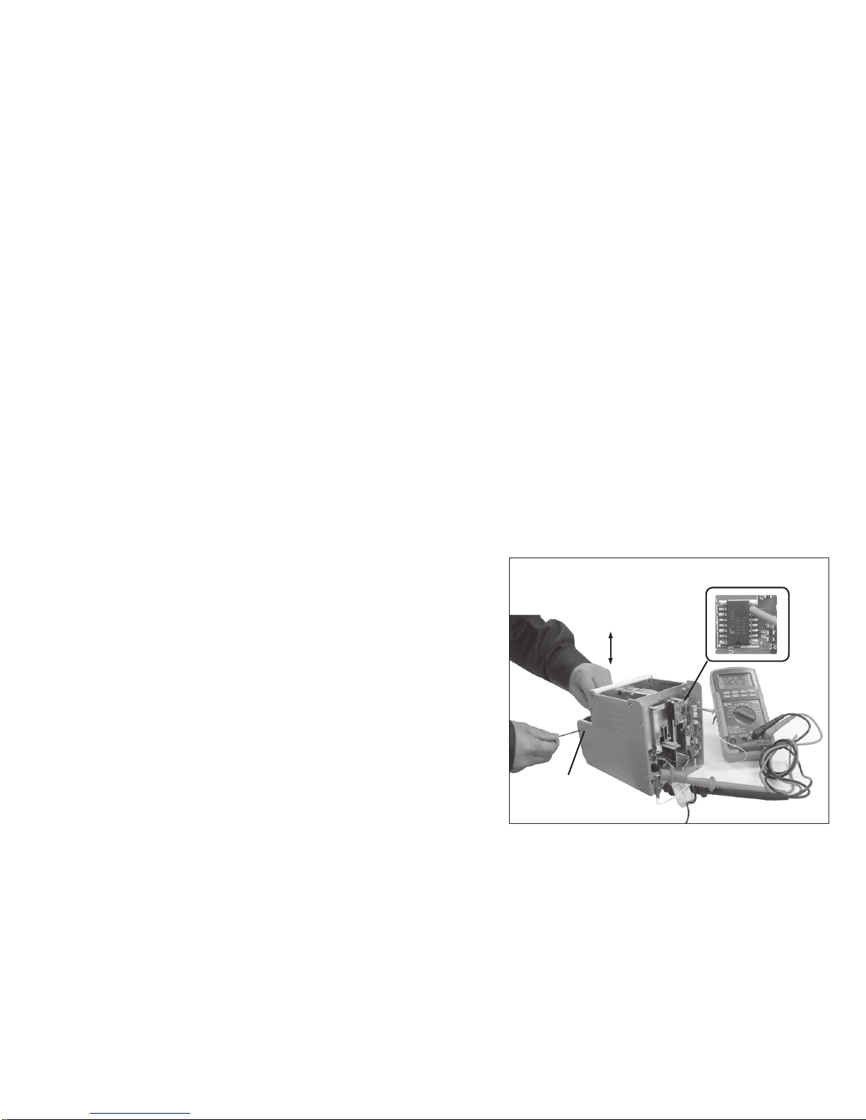
Check/adjustment of rail vibration
Transfer speeds of screws differ according to screw type.
This machine can change rail amplitude and adjust the transfer speed.
* To adjust amplitude, loosen an amplitude xing screw at the rear of
this machine and turn the amplitude adjusting screw at the bottom of
the machine.
Viewing it from the bottom, if turned clockwise, the amplitude becomes
larger, and if turned counterclockwise, the amplitude becomes smaller.
* If you make the amplitude too large in order to speed up the transfer,
it may become difcult to pull up screws. So, adjust it to appropriate
amplitude for the type of screw being used.
* After adjustment is completed, be sure to tighten the amplitude xing
screw on the rear of the machine.
Tilting bolt
・ Loosen the tilting bolts, to
adjust angle of the machine.
・ Keep both sides as the
same height.
Amplitude
xing screw
Larger vibration
Smaller vibration
Amplitude
(Vibration)
adjusting
screw
Page 11
-10-
◆
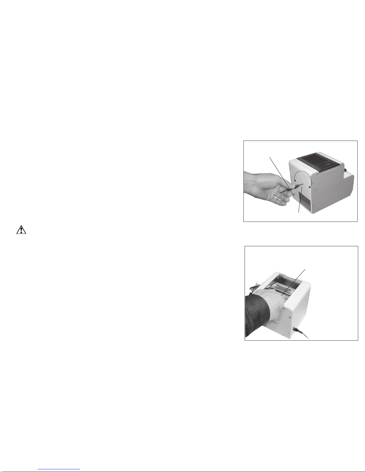
Check of the sensor’s optical axis
If there is no screw at the stopper section, this machine continues operation, and if there are screws, it
stops after a certain period of time has passed. This machine has the level of the screw/no screw sensor
adjusted by the reference rail on shipment. In reality, however, a level adjustment of the sensor may
become necessary when using thin-head screws or due to occurrence of variation on rail replacement.
Then, follow the directions (1) and (2) for the adjustment.
(1)
- Loose the sensor attaching screw on the side lit up as much as it moves by picking up the sensor holder with ngers,
and turn on the power switch.
- Place a screw on the fail within the sensor range.
- Hold the rail end lightly with ngers as much as it doesn’t vibrate so that screws doesn’t pass through.
- When the sensor holder is moved up and down, there is a position the sensor of the receiving light side defects a screw
head and stops the vibration.Tight the sensor attaching screw at this position.
- Comrm whether it really works or not. See if a screw passes through and the sensor detects if and stops.
(2)
* Remove the machine body rear cover, and measure the voltage
level. Adjust the IC4050 7th-pin voltage level. The ground, when measuring it, is the body’s metal part.
* Adjustment is not necessary if the voltage level is within 0.25 to 1.5V
when a rail is and if there is no screw at the stopper section.
* When adjustment is necessary, loosen the sensor attaching screw
on the side. Adjust the voltage level by moving it up and down.
(It is easier to make an adjustment if connector of the main motor is
removed.)
* After the adjustment, throw in the screws and run it practically in order to check the operation.
Note: When no loaded screws are: 0.25 V to 1.5 V
When loaded screws are: 3.5 V or more
Adjusting the sensor attachment
up and down on the side lit up
The sensor attaching
screw on the side lit up
No.7 pin of IC4050
Page 12
-11-
◆
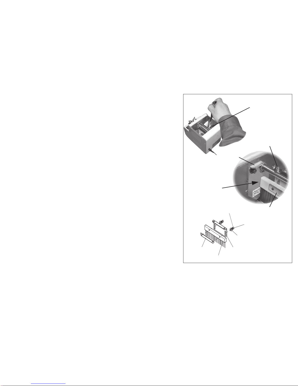
Adjustment and Check of the timer
he speed of screw delivery depends on the actual kind of screw. By adjusting the timer of the machine the screws are picked up smoothly.
* If a screw is picked up on the stopper and the screw coming next is not
picked up for a certain amount of time, the unit stops the operation. Then if
you pick up the screw, it starts operating again. You can change the time by
adjusting the timer within 1 to 6 seconds.
* Time changes after adjusting the times setting volume on the rear of the
machine as shown on the right. Viewing the unit from the back, if it’s turned
clockwise, the time becomes longer, and if it’s turned counterclockwise, the
time becomes shorter.
* Do not use excessive force while making an adjustment. Turn it only as
much as the possible rotating range allows.
◆
The operation check of the overload protection circuit
For overload detection and check of protection circuits:
Try to force the movement of the scooping block to stop, to check the operation of overload detection and overload protection circuits.
If you force the movement of the scooping block to stop for about 4.5 seconds or less, the main motor stops after repeating rotations of
reverse -> forward -> reverse -> ....
To cancel the above operational check, turn off and then turn on the power
switch again.
Caution : Use the screwdriver provided with the machine.
Using other screwdrivers may damage circuit components.
Timer setting volume.
Use the provided
screwdriver.
Check overload detection and protection
circuits by forcing the up-and-down
movement of the scooping block to stop.
To increase
time
To reduce
time
Page 13

-12-
5)
OPERATING INSTRUCTIONS
◆
Supplying screws (Refer to P. 4)
* Set the [scooping block] to the lowest possible position. Remove the top cover of the [scooping chamber]. Throw in
screws up to a position of 2 mm to 3 mm below the rail groove top face.
* In this condition, ensure that the front inclined-face of the ramp is not hidden by the screws.
Caution:
An excessive quantity of screws thrown in may cause a machine malfunction.
◆
Switch-on
* Plug the provided AC adapter into a wall outlet and into the machine.
* Turn on the power switch. The power switch lamp will light up.
* The up-and-down movement of the scooping block and back-and-forth movement of the rail will activate.
* Subsequently, screws are successively sent to the outlet direction. Unless you pick up the screws in the stopper
section, the sensor senses it and the machine stops operation.
* If you pick up the screws in the stopper section, the sensor senses it and the machine resumes operation.
◆
Picking up screws
* When picking screws up, use a bit that ts the screw diameter and groove width of the holding plate.
* Make a motor-driven driver’s bit upright, put it down to the vertical direction along the V groove of the bit guide while
turning it, and pull it out toward yourself when cross recess on the screw head is pick up by the bit.
Caution:
Do not exert any excessive force to the rail at this time. It may cause the machine to malfunction.
◆
Timer settings(Refer to P. 11
)
* If you pick up screws of the stopper section and then do not pull up the next screws for a certain period of time, the
machine stops. Operation will resume again after you pick up screws.
* The time until the machine stops is adjustable within 1 to 6 seconds. Adjust it according to the procedure in the
diagram on the right.
Caution:
Always unplug the AC adapter from the wall outlet before making any adjustments to avoid injury.
Page 14
-13-
6)
REPLACEMENT OF CONSUMABLE PARTS
◆
Replacement of brushes
* If the tip of the brush wears out and does not wipe off a screw from
an abnormal position, replace it with a new brush.
* Turn the machine’s power switch on and off and position the brush
as in the diagram on the right.
(Position it so that the Brush assembly mounting screws can be easily removed.)
* After reassembly, ensure that the brush and the passage plate do
not clash when the Brush assembly moves. The gap is ideally “0”.
* Refer to P. 4, “Check/adjustment of the brush” for mounting adjustments.
Part number of brush assembly:
NSB02053 #01 ⇒ standard part
NSB02053 #02 ⇒ optional part (more bristly)
When the brush is op-
erating, it should not
come in contact with
the passing plate.
Remove the brush
assembly attaching screw
Passing plate
Brush assembly
attaching screw
Brush assembly
(exploded view)
5RTKPIYCUJGT
*GZUQEMGVJGCFUOCNNDQNV
/g
/
/
2NCKPYCUJGT
$TWUJDTCEMGV
$TWUJDTCEMGV
$TWUJ
Page 15
-14-
◆
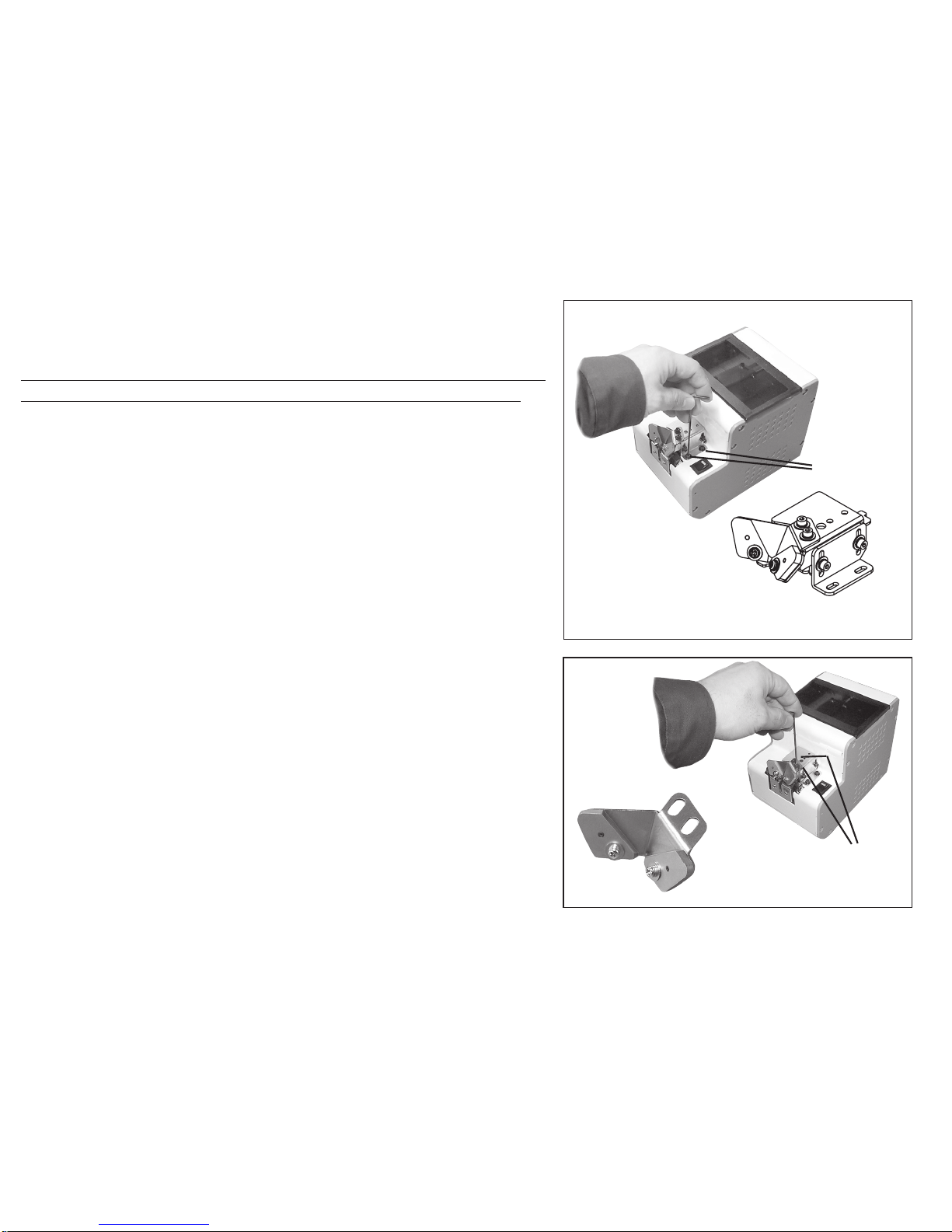
Replacement of the bit guide unit
Replace the holding plate when there is difculty in using it, such as
after excessive wear.
When replacing the holding plate, remove the bit guide section off
the body to prevent a mounting screw from falling inside the body.
* As in the diagram on the right, remove the bit guide section and
replace the holding plate.
* Refer to P. 5, “Check/adjustment of the holding plate” for mounting
adjustments.
Part number of bit guide unit:
NSB06003
◆
Replacement of the bit guide assembly
Replace the bit guide when there is difculty in using it, such as after excessive wear.
* As in the diagram on the right, remove the mounting screws and
replace it.
* Refer to P. 7, “Check/adjustment of the bit guide” for mounting
adjustments.
Part number of bit guide assembly:
NSB06002
Remove the bit guide.
Screws for
adjustment,
2 pieces
Remove the
bit guide.
Fixing screws,
2 pieces
Page 16
-15-
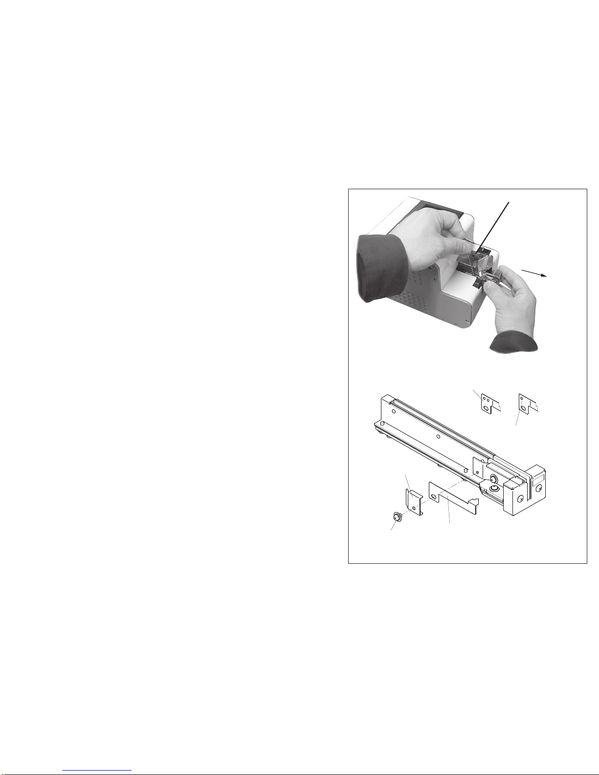
◆
Replacement of the stopper
Replace the stopper when there is difculty in using it, such as after
excessive wear.
* As in the diagram on the right, loosen the rail xing screws and
pull out the rail from the body.
* The stopper can be changed as in the diagram on the right.
* There are three types of stoppers.
* Be careful to correctly match the new stopper to the nominal diameter being used.
Determine the type of stopper by examining the hole of the mounting section.
Part number of stoppers:
φ1.0(M1.0) ⇒ NSB05113
φ1.2-φ1.4(M1.4) ⇒ NSB05114
φ1.7-φ3.0(M3.0) ⇒ NSB05115
Rail xing screw
Pull out the rail
toward you.
ストッパ
ストッパ
固定板
取付ねじ
M2.6×4
本形状
は
φ1.7~
φ3.0用
本形状
は
φ1.
0用
本形状は
φ1.2,φ1.4用
This shape is
for φ1.0.
This shape is for
φ
1.2 andφ1.4.
Stopper xing plate
Fixing screw
2.6mm ×4mm
Stopper
(This shape is for φ1.7-φ3.0.)
Page 17
-16-
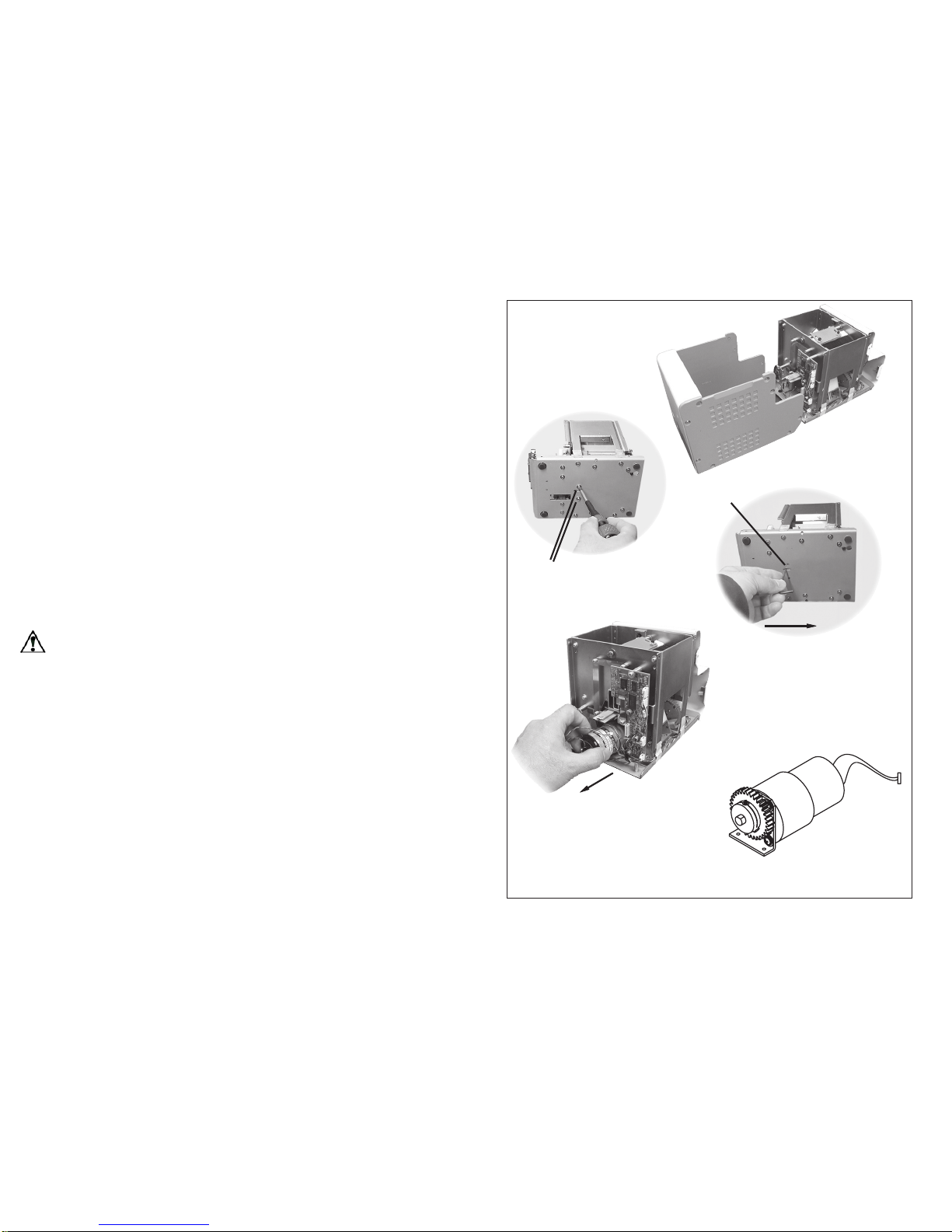
◆
Replacement of the main motor unit
Replace the motor after it is damaged.
* Remove the cover from the body.
(During removal, as in the diagram on the right, the cover
mounting screws should be removed together with the front
cover, leaving the four screws of the rear in place.)
* Remove the motor trunk connector.
* Remove the motor mounting screws on the motor’s
bottom face.
* Pull out the motor section from the rear of the body.
(To facilitate removal, insert a hexagonal wrench or the like
into the long hole of the body base and push the motor mounting bracket backward.)
* Be careful not to break motor wires by using overly
excessive force.
Caution:
Unplug the AC adapter from the wall outlet before
disassembly of the motor section.
Main motor unit
Remove the motor mounting
screws
(2.6mm×8mm, 2 pieces)
The long hole
Push the motor mounting
bracket backward.
Pull out the motor section
from the rear of the body.
Remove the cover
Page 18
-17-
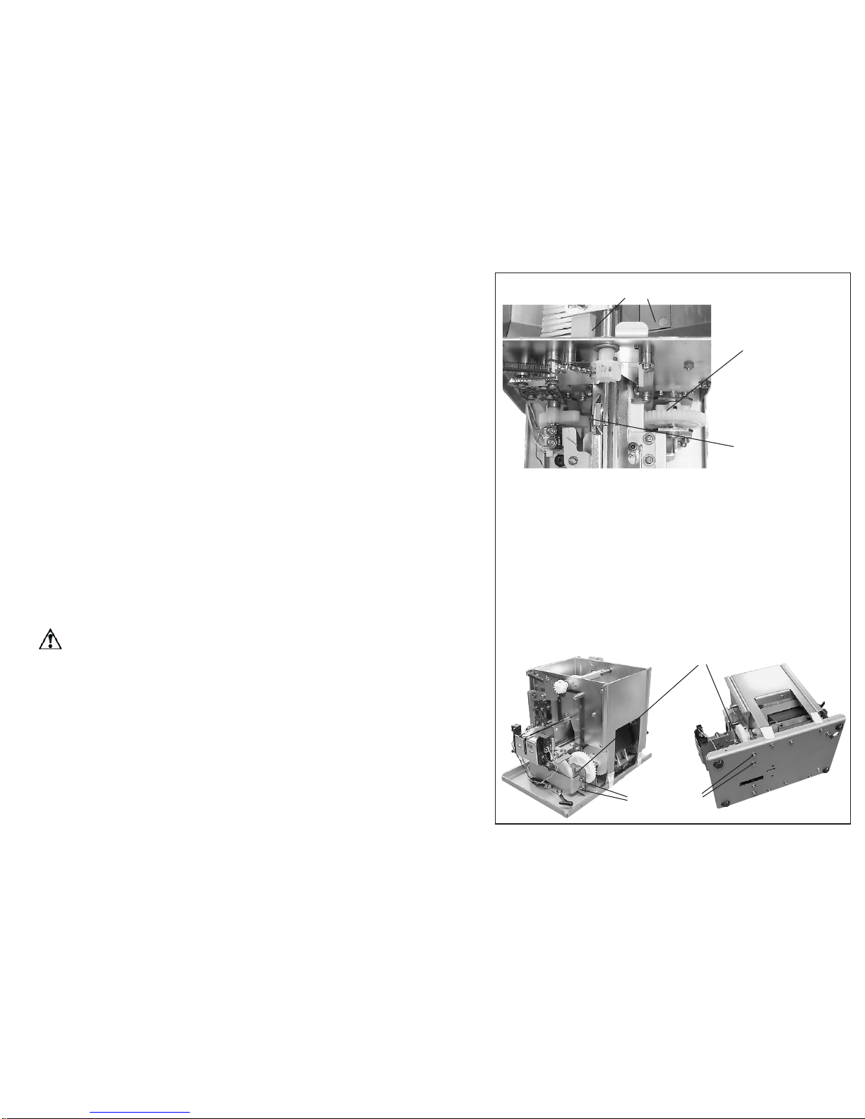
◆
Movement timing when replacing a motor
* To time a movement of the [scooping block] and that of a brush,
the gears must be in mesh.
* If only the motor section is removed from the body, the
movements can be timed by reassembling the motor section
according to the timing in the diagram on the right.
* If it is difcult to mesh the driving gear of the motor section with
the right and left trailing gears. Assembly can be made easier by
loosening the mounting of the right driving shaft bracket (see the
diagram on the right). Be sure to refasten the loosened screws
after mounting the motor section.
* After mounting, start the motor and check the movement timing.
(The right and left [scooping blocks] must move up and down
almost simultaneously.)
* After checking the movement, refer to the wiring diagram and
properly position the wiring.
(Avoid wires being caught when mounting the cover and be careful
not to break motor wires by using overly excessive force.)
Caution:
Unplug the AC adapter from the wall outlet before
disassembly of the motor section.
Part number of main motor unit:
NSB03056
* Assemble the motor when [scooping block] is on the right
and left as much as possible.
* In order to make the height of [scooping block] on the right
and left just about the same, the driving gear attached to
the motor axis and the sub-driving gear on the right and left
must be in mesh. Then, tighten the screws (8mm×8,
2 pieces) for the motor bracket.
Drop [scooping block] on the right and left
as much as possible.
The pin is
approximatwly
vertical.
The pin is
approximatwly
inclined 46
degrees.
When the gears do not t:
Loosen the following screws and free the driving shaft
bracket, and it makes the gear easier to be in mesh.
Driving shaft bracket
Attaching screws in 4 places
Page 19
-18-
7
) OTHERS
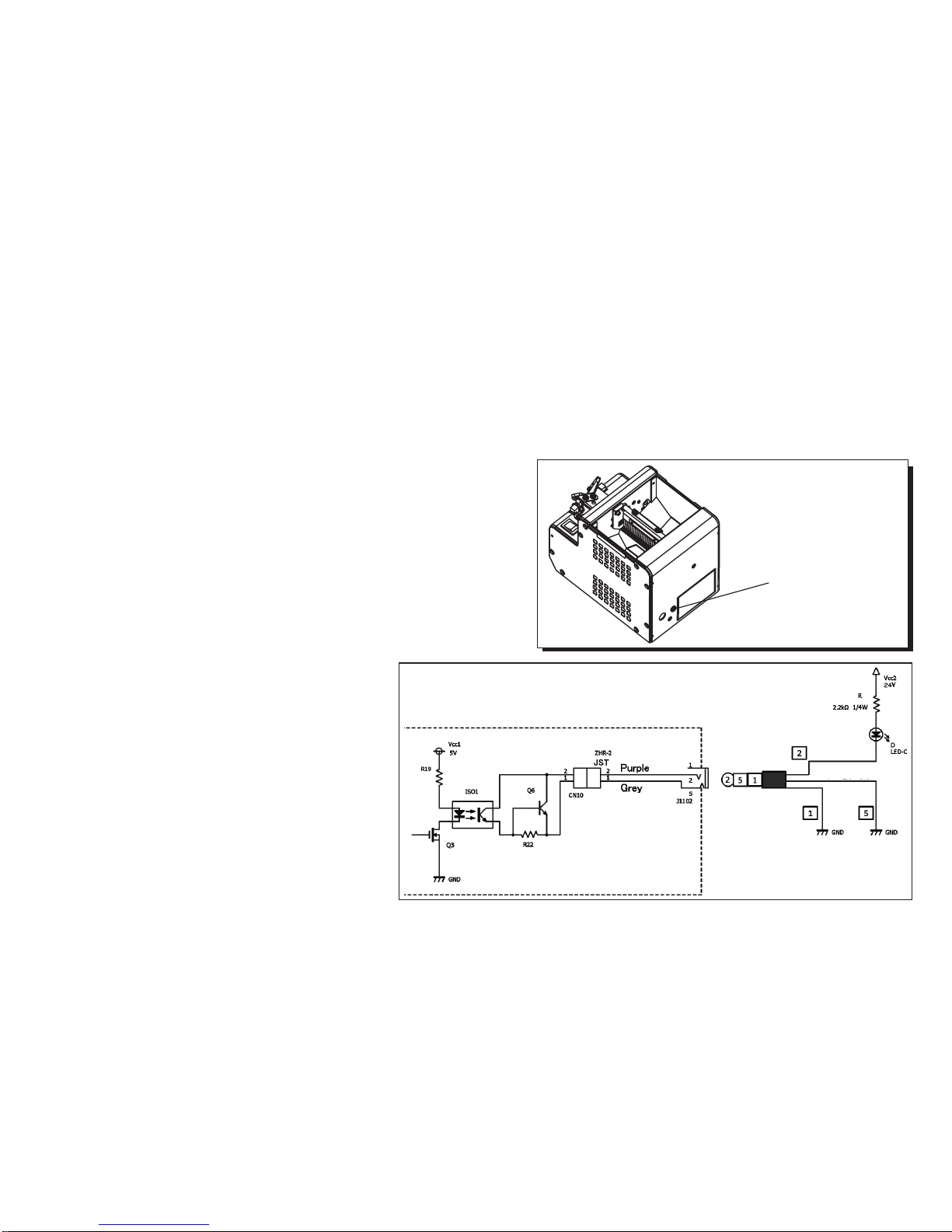
◆
Eeternal output signals
The jack on the back of the machine serves as the detection of
picked screw up, which shall be used with external screw counters.
[Function]: When picked screw up : signal high (ON) approx. 0.2sec
Incoming current: shall be limited to less than 100mA
**CAUTION: Additional resistor is required on
external circuit for regulating current **
[Capacity]: Max DC current: 100mA
External supply voltage: 5 ~24VDC (Max: 27VDC)
[caution]: Please use the plug type of φ3.5-3conductor
miniature jack.
Recommended type:
Marushin Electric Mfg.Co.,Ltd.
MP-019LC (Straight type)
MP-012LN (Right angle type)
Recommended connector cable:
Marushin Electric Mfg.Co.,Ltd.
MC-35ST (
Straight type)
MC-35STL
(Right angle type)
Example of connection
Inseide of the feeder
Outseide of the feeder
High voltage
Low voltage
MJ-352W-O
Signal output jack
Page 20

-19-
8)
TROUBLESHOOTING (Please check the following before asking for a repair.)
Caution:
Unplug the AC adapter from the wall outlet before and while making any adjustments to avoid injury or machine malfunction.
Trouble Cause
Measures
7-1
The machine does not operate though the switch has
been turned on.
* Power is not supplied.
* Screws in the stopper section have not
been taken away for a certain period of
time.
* Excessive quantity of screws is placed in
the [scooping chanber].
* A foreign object (for example: a screw)
intruded into the main body.
* The AC adapter is faulty.
* Conrm the power supply connection
of the AC adapter.
* Take away the screws in the stopper
section.
* Adjust the timer setting volume.
* Adjust the number of screws in the
[scooping chanber].
* Remove the foreign object.
* Consult your dealer.
[model number: UI315-15]
7-2
Screws do not feed.
* Screws of a larger nominal diameter than
that prescribed for Rail Assembly are being used.
* The quantity of screws in the [scooping
chanber] has become too small.
* The abnormally positioned screws are
not completely removed by the brush on
the passage plate.
* Use the screws of the prescribed
nominal diameter.
* Remove abnormal screws.
* Place adequate quantity of screws in
the [scooping chanber].
* Adjust the brush.Adjust the passage
plate.The situation may improve by
placing adequate number of screws in
the [scooping chanber].
Page 21

-20-
Trouble Cause Measures
7-2
Screws do not feed.
* A shank of a screw is caught in the
passage plate.
* A screw has stopped in an abnormal
position in the middle of the rail.
* The rail is not moving back and forth
(screws are caught in a gap).
* Remove abnormal screws.Next, adjust
the passage plate.
* Remove the screw in an abnormal
position.
Remove it as follows:
Loosen the Bit Guide Assembly fixing
screws.
Move the bit guide upwards.
Incline the machine and remove the
screw in an abnormal position from the
rail tip. Next, adjust the holding plate.
* Remove the screws stuck in the gap.
If none are stuck, call for repair service.
7-3
Screws have dropped into
the rail groove.
* Screws of a smaller nominal diameter
than that prescribed for the Rail Assembly
have been put in.
* The gap between the holding plate and
the screw head is too small.
* Use the screws of the prescribed
nominal diameter.
* If the problem is not solved, please call
your distributor.
Page 22

-21-
Trouble Cause
Measures
7-4
The screws on the rail are
not feeding smoothly.
* The gap between the holding plate and
the screw head is too small.
* Screws with spring washer, of one
rank lower in nominal diameter than
that prescribed for the Rail Assembly are
loaded.
* The rail may be covered with dust or oil.
* The rail doesn’t move back and forth.
(Screws are stuck in a gap.)
* The motor may be damaged or worn out.
* Adjust the bit guide assembly (together
with the holding plate).
* Run the machine on an incline. (If this
does not solve the problem, please call
your distributor.)
* Clean the rail and rail guide.
* Remove the screws stuck in the gap.
* Replace the motor.
7-5
The screws often run in an
abnormal position through
the passage plate.
* Inadequate adjustment of the passage
plate.
* The machine is set front inclined
downwards more than prescribed.
* Adjust the passage plate.
* Set it front inclined downwards within
the prescribed value.
Page 23

-22-
Trouble Cause Measures
7-6
The screws often run in an
abnormal position through the
passage plate.
A screw has stopped in an abnormal
position in the middle of the rail.
* Adjustment of the front and back positions
for Rail Assembly is incorrect.
* Adjust the bit guide and holding plate.
* Adjust the Rail Assembly back and
forth.
7-7
Screws are not feeding at the
bit guide’s outlet.
* The front and back positions are not on
the right places.
* The right and left positions are not on the
right places.
* Adjust the Rail Assembly back and
forth.
* Adjust the bit guide and the holding
plate.
7-8
The machine suddenly stops
operation.
* Due to an overload, the over-current
protection circuit has operated.
* Too many screws are in the .
* A screw is caught in the clearance.
* A screw, at the extraction site, could not
be extracted for an amount of time.
* Turn on the power switch again.
* Remove the cause of overload.
* Remove screws to a proper level.
* If the problem is not solved, please
call your distributor.
* Remove the screw that is caught.
* Remove the screw.
Page 24

-23-
Trouble Cause Measures
7-9
A screw has dropped inside
the machine.
* Shake off the screw from the hole on
the back of the machine.
7-10
There are screws in the
stopper section, but the
machine does not stop
operation.
* There’s deviation of the rail and sensor
positions.
* If the positions are on the right places.
* Move the rail back and forth and adjust
it in a position where the operation
stops.
* Adjust the sensor height.
7-11
If screws in the stopper
section are taken out, but it
does not perform the next
operation.
* The sensor is not adjusted.
* A wire connected to a sensor is snapped.
.
* Adjust the sensor height.
* Fix it by soldering.
* Replace sensor assembly.
* Grease has run out.
7-12
The sound of the machine becomes louder.
* Apply grease to the driving section.
Recommended grease:
BR2 Plus
Dow Corning Asis Co.,Ltd
Page 25
-24-
9) SPECIFICATIONS
[Caution]
- AC adapter which attaches to an old type NSB series can't be used.
- Check if the axis diameter of the loaded screw corresponds with the
below rail groove width.
- With the range of screw size and lengths below, there may be
instances lf unique screw shape or stracture not com;atible with the
screw feeder unit.
- In the main body type, the main body model can be changed.
- To change the nominal diameter of loaded screw, replace it with a part
that is mentioned in the next page table.
- The rail and passing plate are separately available for replacement.
- The design, performance and specifications are subject to change
without prior notice for the sake of improvement.
※ Compatible with washer diameter up to 9 mm, thickness 0.35 to 1.0mm.
Input:AC100~240V 50/60Hz
Output:DC15V 1A
Dimensions 123(W) × 181(D) × 145(H) (mm)
Weight Approx. 2.9Kg (including rail)
Screw capacity Approx. 80cc
Following
accessories
Operation Manual 1 copy
AC Adapter 1 unit
Passing Plate 2 pieces (one is already installed.)
Hexagonal Wrench 1 piece
Screwdriver 1 piece
0.35 mm gauge plate 1 piece
Power
AC adapter
(switching type)
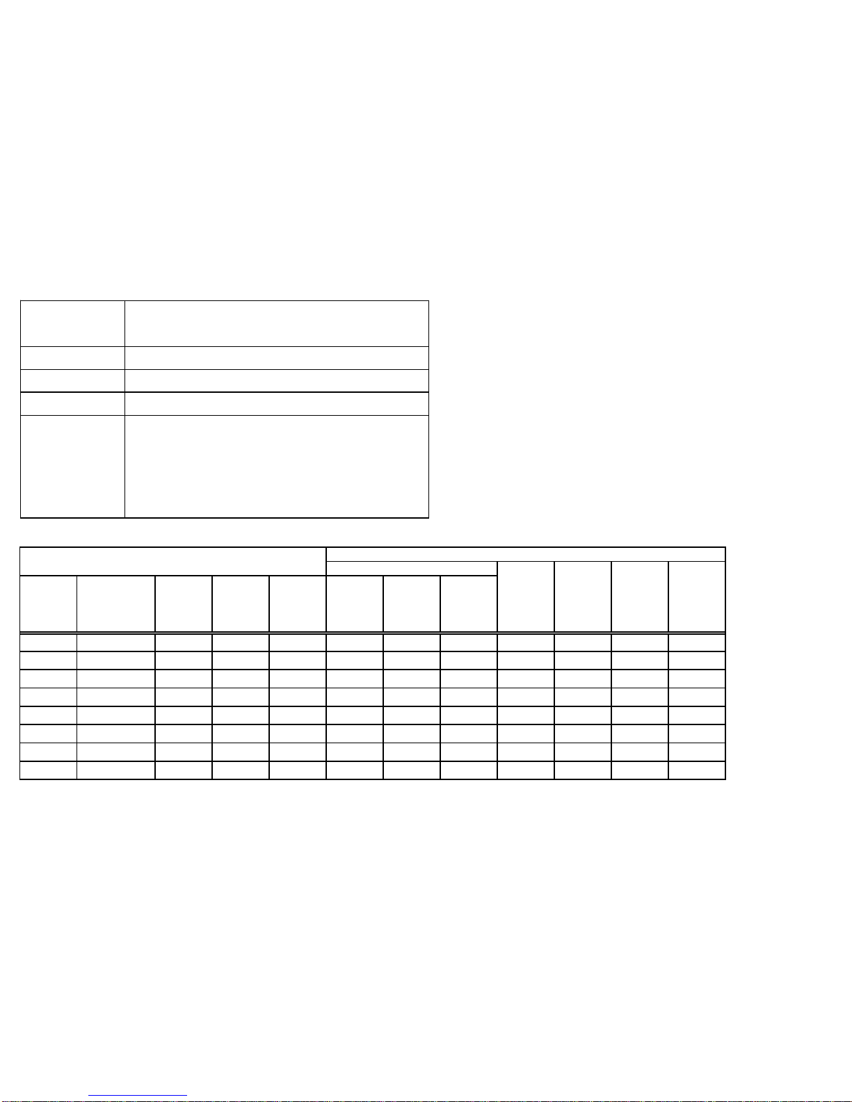
Reference table of the specified screws
Screw
size
Screw shaft
diameter(φ )
Screw
head
diameter
(φ )
Screw
head
thickness
(mm)
Screw
shaft
length
(mm)
Sems
Double
sems
Washer
head
Shape of screw head
Pan head
bind
Flat head
Counter
sunk
head
hexagon
flange
bolt
Page 26
-25-
○
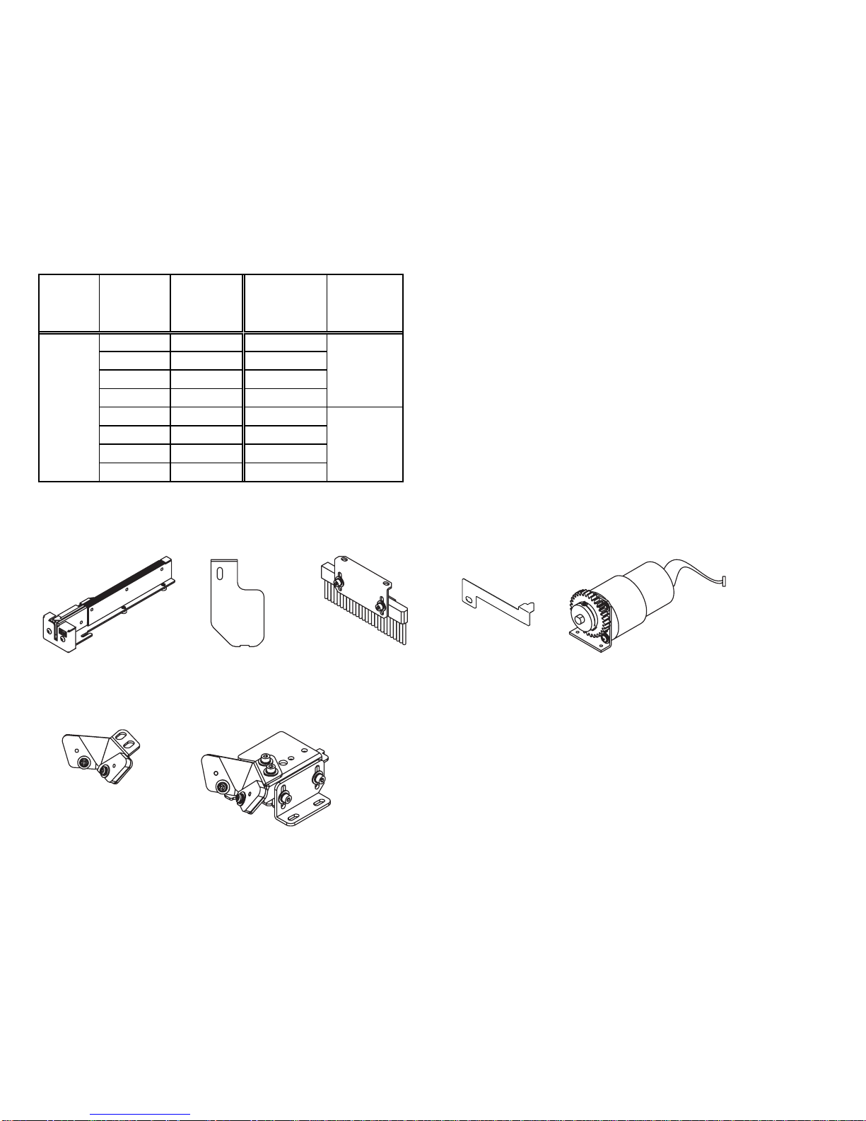
Replacement parts
・ Rail
・ Passing plate
・ Brush assembly
NSB02053 #01
・ Stopper
・ Main motor unit
NSB03056
・ Bit guide assembly
NSB06002
・ Bit guide unit
NSB06003
Reference table of the specified screws
Screw
feeder
series
Screw
feeder
model
Screw size Rail model No.
Passing plate
model No.
Screw
size
Screw shaft
diameter(φ )
Screw
head
diameter
(φ )
Screw
head
thickness
(mm)
Screw
shaft
length
(mm)
Sems
Double
sems
Washer
head
NSB²-10
φ 1.0 SR10 φ 1.0 0.9~0.95 1.2~4.5 0.35~1.0 1.6~10 ○
NSB²-12
φ 1.2 SR12 φ 1.2 1.1~1.15 1.4~4.5 0.35~1.0 1.8~10 ○
NSB²-14
φ 1.4 SR14 φ 1.4 1.3~1.4 1.7~4.5 0.35~1.0 2.0~10 ○
NSB²-17
φ 1.7 SR17 φ 1.7 1.6~1.7 2.0~4.5 0.35~1.0 2.3~10 ○
NSB²-20
φ 2.0 SR20 φ 2.0 1.9~2.1 2.4~6 0.35~4.5 2.6~20 ○ ○ ○ ○ ○ ○ ○
NSB²-23
φ 2.3 SR23 φ 2.3 2.2~2.4 2.7~6 0.35~4.5 2.9~20 ○ ○ ○ ○ ○ ○ ○
NSB²-26
φ 2.6 SR26 φ 2.6 2.5~2.7 3.0~6 0.35~4.5 3.2~20 ○ ○ ○ ○ ○ ○ ○
NSB²-30
φ 3.0 SR30 φ 3.0 2.9~3.2 3.5~6 0.35~4.5 3.6~20 ○ ○ ○ ○ ○ ○ ○
NSB²
SW1017
SW2030
Shape of screw head
Pan head
bind
Flat head
Counter
sunk
head
hexagon
flange
bolt
Page 27
-26-
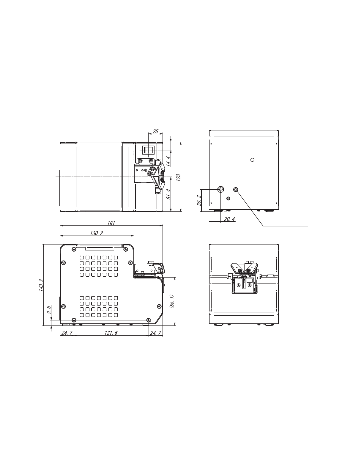
10) EXTERNAL DIMENSIONS
Unit :
mm
Signal output jack
Page 28

-27-
11) WARRANTY
For users within Japan, the effective term of warranty is 6 months after delivery.
Such warranty will not be applicable to purchases or users outside of Japan.
If any troubles should occur, please contact your dealer.
After the warranty period, repair services will be completed.
In the following cases, the purchaser shall pay for parts and labor regardless of the terms of
warranty:
① Failure due to improper handling.
② Failure due to product modication or improper processing.
③ Failure due to causes beyond control (for example earthquake or re).
④ Failure attributable to any cause other than this product.
⑤ Consumables (brushes, bit guide, main motor, holding plate, stopper)
and replaceable parts and replacement work expenses.
The repair parts shall be available within 5 years after purchase.
Page 29
-28-
「Quicher」 「OHTAKE」 「OHTAKE ・ ROOT KOGYO」 are trademarks or/and registered trademarks of OHTAKE ・ ROOT KOGYO CO.LTD.]
「Quicher( クイッチャー)」 「OHTAKE」 「OHTAKE ・ ROOT KOGYO」 は、 株式会社 大武 ・ ルート工業の商標又は登録商標です。
The specifications and/or design may be altered, without notice, whenever there are changes or improvements.
改良のため、 予告なくデザイン、 性能、 仕様等を変更することがあります。
Photocopying, reproduction or publication, in whole or in part, of this manual, without permission, is strictly prohibited by copyright law.
この取扱説明書の一部または全部の無断転載、 複製を禁じます。
© Copyright OHTAKE ・ ROOT KOGYO CO.,LTD.
岩手県一関市萩荘字金ヶ崎
27 〒021-0902
Tel 0191-24-3144
Fax 0191-24-3145
27 Kangasaki Hagisyou
Ichinoseki
Iwate, 021-0902 JAPAN
Tel +81-191-24 -3144
Fax +81-191-24-3145
http://www.ohtake-root.co.jp
(as of November, 2014)
(2014 年 11 月現在 )
27 Kanegasaki Hagisho Ichinoseki
Iwate, 021-0902 JAPAN
Tel +81-191-24-3144
Fax +81-191-24-3145
岩手県一関市萩荘字金ヶ崎27〒
021-0902
Tel +81-191-24-3144
Fax +81-191-24-3145
(as of Jun. 2016)
(2016 年 6 月現在 )
 Loading...