

Page 1

Order Number
: GETEC-C1-11-074
FCC Part 15 subpart B
Test Report Number
: GETEC-E3-11-024 Page 1 / 1
APPENDIX H
: USER’S MANUAL
EUT Type: RF BASE STATION
FCC ID.: OZ5URCMRF250C
Page 2
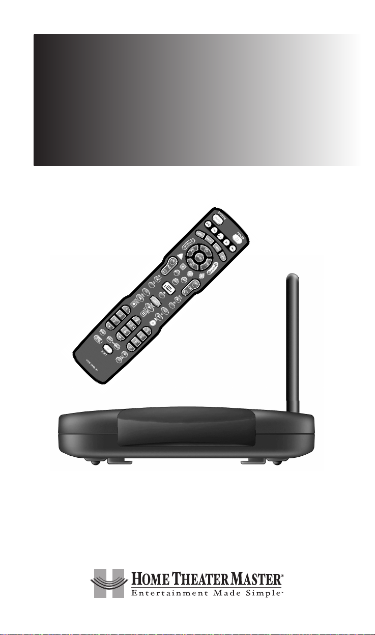
Multi-Room “No-Pointing” RF Control of
Cable Box/your Components
MRF-250C
INSTALLATION
MANUAL
Page 3

500 Mamaroneck Avenue, Harrison, NY 10528
Phone: (914) 835-4484 Fax: (914) 835-4532
MRF-250C Installation Manual ©2011 Universal Remote Control, Inc.
The information in this manual is copyright protected. No part of this manual may be copied
or reproduced in any form without prior written consent from Universal Remote Control, Inc.
UNIVERSAL REMOTE CONTROL, INC. SHALL NOT BE LIABLE FOR OPERATIONAL, TECHNICAL OR EDITORIAL ERRORS/OMISSIONS MADE IN THIS MANUAL.
The information in this manual may be subject to change without prior notice.
Home Theater Master is a registered trademark of Universal Remote Control, Inc.
Entertainment Made Simple is a trademark of Universal Remote Control, Inc.
All other brand or product names are trademarks or registered trademarks of their respective
companies or organizations.
Page 4

TABLE OF CONTENTS
Introduction 1
Features and Benefits 2
Parts Guide 2
MFS-250C Details 3
A Standard MRF-250C System 5
Front Blaster Overload 6
RF Setup Method for remote 6
Frequently Asked Questions 6
USA Limited Warranty Statement 7
Specifications 8
Federal Communication Commission Interference Statement 9
Page 5
Page 1
MRF-250C BASE STATION
Introduction
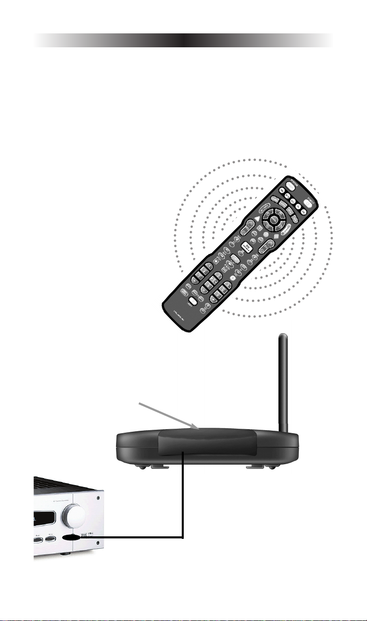
The combination of the UR5L-9000LRF with it’s companion MRF-250C base
station will enable you to place your Cable Box/your components out of sight
behind closed doors or in another room of your house. The MRF-250C
converts commands to infrared signals that control you AV components. This
allows the UR5L-9000LRF to send radio signals throughout your house
whether you be indoors, outdoors, or even up to 100’ away.
1. The UR5L-9000LRF remote
control sends radio waves in
every direction, so you don’t
have to point the remote at the
device anymore!
2. The MRF-250C’s built-in Front Blaster sends commands to
components in the same cabinet space as the MRF-250C.
3. Self-adhesive “Flashers” affix to the
Infrared sensors on the front panels
of your components. The Flashers relay
commands to components out of sight
of the MRF-250C’s Front Blaster. The
flashers plug in to the MRF-250C’s rear
allowing the flasher line to output via
their 10 foot cables.
Page 6

Page 2
MRF-250C BASE STATION
Features and Benefits
No More Pointing - Radio Waves Penetrate Walls, Doors and Floors
The MRF-250C receives the RF signals of the UR5L-9000LRF remote control from
any direction. You no longer need to point the remote control at any of your AV
components. You can also place the components distracting blinking lights and
displays behind closed doors or in another room!
Reliable Control Throughout Your House
The MRF-250C receives RF signals from your UR5L-9000LRF from within a radius
of 50 to 100 feet enabling you to control out of sight cable boxes or components
such at those behind walls or closed doors. Range depends on the structure of your
home and the amount of interference generated by computers, microprocessors
and other devices within and nearby your home.
Control an Equipment Locations Controlled From Any UR5L-9000LRF
Each UR5L-9000LRF can be programmed to operate equipment in another room,
by installing an MRF-250C base station at each location. The MRF-250C is assigned
one of 16 unique ID#s. In operation it is simple: when you select a device located in
the den, the UR5L-9000LRF only signals to the MRF-250C in the den.
No Pointing Remote Controls In Every Room
You can opt to control a multi-room or multi-zone system via RF remote control
by placing a UR5L-9000LRF in each room of your home.
Parts Guide
The MRF-250C RF Base Station includes:
1 - MRF-250C Receiver with integrated antenna
1 - Mounting Plate for wall mounting the MRF-250C
4 - Screws for wall mounting the mounting plate
1 - 9V-300mA Power Supply
6 - Flashers with 10 foot plug in cables.
Page 7
Page 3
MRF-250C BASE STATION
MRF-250C Details
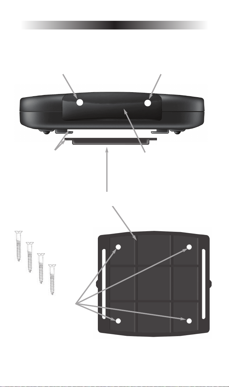
Using the four enclosed
screws, you can choose to fix
the mounting plate to a wall or
the back of your component
cabinet.
The MRF-250C’s slots enable the
mounting plate‘s matching guides
to slide and “snap” into place for
quick and easy mounting on the
wall.
Front Blaster sends Infrared commands
to all AV components in the same
cabinet space.
Red POWER LEDLights up when the
MRF-250C’s power supply is plugged
into an active AC outlet.
Red STATUS LED Lights up when
the MRF-250C receives an RF
signal from the UR5L-9000LRF.
The MRF-250C Mounting Plate
Page 8
Page 4
MRF-250C BASE STATION
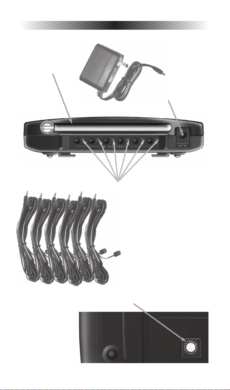
Bottom panel Dial sets the Receiver ID# when
more than one MRF-250C receiver is used.
Included 9V power supply
plugs into the MRF-250C’s
power connector.
Integrated Antenna
swings in any direction
to optimize RF reception and range.
Six Rear Flasher Line Output Jacks
connect flashers for control of A/V
components out of sight of the MRF250C’s Front Blaster.
Six Plug-In Flashers are supplied
with 10 foot cables and six extra
self-adhesive pads in case a flasher
has to be repositioned.
Page 9

A Standard MRF-250C System
A standard system utilizes one UR5L-9000LRF and one MRF-250C to control
an equipment location.
Step 1 - Place the MRF-250C
The MRF-250C should be placed so that the Front Blaster will control as many
of the system’s AV components as possible. If you are connecting the outboard
flashers to the rear Flasher outputs only, the MRF-250C may be concealed and
mounted to the rear wall or back of the system cabinet. The mounting plate
slides apart from the receiver, screws to the wall or cabinet with the enclosed
screws, then the receiver is slid back into place.
Step 2 - Connect the Power Supply and Insert the Batteries
Connect the 9V power supply to an active UNSWITCHED AC outlet. The MRF250C must always be powered up to operate. The red POWER LED should Light
up. Insert the batteries in the UR5L-9000LRF remote control.
Step 3 - Test the UR5L-9000LRF
Observe the MRF-250C’s STATUS LED blinking while you press and hold a pro-
grammed button (one with an actual command). This tells you that the MRF-250C
is receiving the RF commands of the UR5L-9000LRF. However, if the LED
continues to flicker after you release the button, you are receiving RF Interference
and you must move the MRF-250C to another location.
Step 4 - Orient the Antenna for Optimum Range
If you need to extend the range of the remote, try adjusting the angle of the
MRF-250C receiving antenna via it’s pivoting ball mount.
Step 5 - Test Operation Without Flashers
With the UR5L-9000LRF IR output blocked by a jacket or pillow, test the control
of your components using just the Front Blaster. In most cabinets, the MRF-250C’s
Front Blaster will control any AV components in the same cabinet space by
reflections from the cabinet walls and doors. Make sure that the components
operate with the cabinet doors closed or open.
If a component is placed too far away from the front blaster, you will need to
utilize the included Flashers plugged into the MRF-250C’s rear Flasher Line
Output jacks.
Step 6 - Connect Flashers to Out of Sight A/V Components
Important Note: Test the operation BEFORE sticking the flasher in place.
Use a flashlight to identify the correct location of the component’s IR sensor,
then try a few commands while moving the flasher around the face plate of
the component. The most reliable operation typically occurs a half inch or so
away from the IR sensor.
Page 5
MRF-250C BASE STATION
Page 10

Page 6
MRF-250C BASE STATION
Once you have found the spot that gives the most reliable operation, peel off
the protective backing of the self-adhesive tape on the included Flashers and
stick them in place.
Important Note: Always replace the self-adhesive tabs if you have to reposition a flasher. Six extra self-adhesive tabs are supplied for this purpose.
Front Blaster Overload
A few models of Cable Box or your components can be OVERLOADED by
the Front Blaster. If you are having intermittent or inconsistent results with a
particular component, try repositioning the MRF-250C and facing the Front
Blaster in a different direction. If this improves the situation but is impractical, it
may be necessary to utilize the self-adhesive flashers only. This will limit the
number of components your MRF-250C can control to six.
RF Setup Method for remote — Step by Step
Step 1 -
After installing the MRF-250C, press the [CBL] and [LIST] button simultaneously
for 3 seconds. The [CBL] device LED will turn on indicating that it is ready to
be programmed. The LED will remain on for 30 seconds.
Step 2 -
After installing the MRF-250C, press the [CBL] and [LIST] button simultaneously
for 3 seconds. The [CBL] device LED will turn on indicating that it is ready to be
programmed. The LED will remain on for 30 seconds.
Step 3 -
Once you have completed RF ID setting, Store the 2-digit number by
pressing the [CBL] button once again. The [CBL] device LED will blink
twice to confirm that the RF ID number has been stored.
Note - Install and select the ID # on the MRF-250C. (For further details, refer to
the MRF-250C manual.) You can operate up to 15 different equipment
locations, each with an MRF-250C unique Receiver ID #
Frequently Asked Questions
Can I use flasher/emitters that I have already installed in the system to connect to the MRF-250C?
Yes, the flashers are compatible, however flashers from other companies are equipped
with a mini plug that is too large to fit the MRF-250C’s flasher jacks. Use Radio Shack
part # 274-327 to convert 3.5mm plug Flasher/Emitters to the MRF-250C.
How can I increase the range of the UR5L-9000LRF?
Often, you can increase range by repositioning the MRF-250C and/or by re-orienting
the antenna.
Try to avoid placing the MRF-250C directly adjacent to satellite
receivers, personal computers or any other component using high speed
microprocessors if possible.
Page 11

Page 7
MRF-250C BASE STATION
USA Limited Warranty Statement
Your Universal Remote Control, when delivered to you in new condition, is
warranted against defects in materials or workmanship as follows:
UNIVERSAL REMOTE CONTROL, INC. warrants this product against
defects in material or workmanship for s period of one (1) year and as set
forth below. Universal Remote Control will, at its sole option, repair the
product using new or comparable rebuilt parts, or exchange the product for a
comparable new or rebuilt product. In the event of a defect, these are
your exclusive remedies.
This Limited Warranty covers only the hardware components packaged
with the Product. It does not cover technical assistance for hardware or
software usage and it does not cover any software products whether or
not contained in the Product; any such software is provided "AS IS"
unless expressly provided for in any enclosed software Limited Warranty.
To obtain warranty service, you must deliver the product, freight prepaid,
in its original packaging or packaging affording adequate protection to
Universal Remote Control at the address provided in the Owner’s Manual.
It is your responsibility to backup any macro programming, artwork,
software or other materials that may have been programmed into your
unit. It is likely that such data, software, or other materials will
be lost during service and Universal Remote Control will not be
responsible for any such damage or loss. A dated purchase receipt,
Bill of Sale, Installation Contract or other verifiable Proof of Purchase is
required. For product support and other important information visit
Universal Remote Control’s website: http://www.UniversalRemote.com
or call the Customer Service Center (914) 835-4484.
This Limited Warranty only covers product issues caused by defects in
material or workmanship during ordinary consumer use. It does not cover
product issues caused by any other reason, including but not limited to
product issues due to commercial use, acts of God, third-party installation,
misuse, limitations of technology, or modification of or to any part of the
Universal Remote Control product. This Limited Warranty does not cover
Universal Remote Control products sold as USED, AS IS, REFURBISHED, socalled “B STOCK” or consumables (such as batteries). This Limited
Warranty is invalid if the factory-applied serial number has been altered
or removed from the product. This Limited Warranty is valid only in the
United States of America. This Limited Warranty specifically
excludes products sold by unauthorized resellers.
Page 12

Page 8
MRF-250C BASE STATION
LIMITATION OF REMEDIES
UNIVERSAL REMOTE CONTROL SHALL NOT BE LIABLE FOR ANY
INCIDENTAL OR CONSEQUENTIAL DAMAGES FOR BREACH OF
ANY EXPRESS OR IMPLIED WARRANTY OR CONDITION ON THIS
PRODUCT. IN NO EVENT SHALL UNIVERSAL REMOTE CONTROL
BE LIABLE, WHETHER IN CONTRACT OR IN TORT (INCLUDING
NEGLIGENCE) FOR DAMAGES IN EXCESS OF THE PURCHASE
PRICE OF THE PRODUCT, ACCESSORY OR SOFTWARE, OR FOR
ANY INDIRECT, INCIDENTAL, SPECIAL OR CONSEQUENTIAL
DAMAGES OF ANY KIND, OR LOSS OF REVENUE OR PROFITS,
LOSS OF BUSINESS, LOSS OF INFORMATION OR DATA,
SOFTWARE OR APPLICATIONS OR OTHER FINANCIAL LOSS
ARISING OUT OF OR IN CONNECTION WITH THE ABILITY OR
INABILITY TO USE THE PRODUCTS, ACCESSORIES OR SOFTWARE
TO THE FULL EXTENT THESE DAMAGES MAY BE DISCLAIMED BY
LAW.
EXCEPT TO THE EXTENT PROHIBITED BY APPLICABLE LAW,
THERE IS NO OTHER WARRANTY EXPRESSED OR IMPLIED.
UNIVERSAL REMOTE CONTROL WILL NOT BE HELD RESPONSIBLE
FOR STATEMENTS MADE BY OTHERS CONCERNING THE
MERCHANTABILITY OR FITNESS FOR A PARTICULAR PURPOSE ON
THIS PRODUCT. Some states or jurisdictions do not allow the exclusion
or limitation of incidental or consequential damages, or allow limitations
on how long an implied warranty lasts, so the above limitations or
exclusions may not apply to you. This Limited Warranty gives you
specific legal rights and you may have other rights which vary from state
to state or jurisdiction to jurisdiction.
REV020708
Specifications
MRF-250C
Power Supply: 9V 300mA
IR Flasher Line Outputs: 2.5mm Mono Mini Jack
RF Frequency: 418MHz
Size: 5 1/8” x 3.5” x 1.25” (4.5” antenna up)
Page 13

Page 9
MRF-250C BASE STATION
Federal Communication Commission
Interference Statement
This equipment has been tested and found to comply with the limits for a
Class B digital device, pursuant to part 15 of the FCC Rules. These limits are
designed to provide reasonable protection against harmful interference in a
residential installation. This equipment generates, uses and can radiate radio
frequency energy and, if not installed and used in accordance with the instructions, may cause harmful interference to radio communications.
However, there is no guarantee that interference will not occur in a particular
installation. If this equipment does cause harmful interference to radio or television reception, which can be determined by turning the equipment off and
on, the user is encouraged to try to correct the interference by one more of the
following measures:
Reorient or relocate the receiving antenna.
Increase the separation between the equipment and receiver.
Connect the equipment into an outlet on a circuit different from
that to which the receiver is connected.
Consult the dealer or an experienced radio/TV technician for help.
Warning!
Changes or modifications not expressly approved by the manufacturer could
void the user’s authority to operate the equipment.
Note : The manufacturer is not responsible for any Radio or TV interference
caused by unauthorized modifications to this equipment. Such modifications
could void the user’s authority to operate the equipment.
FCC Caution
This device complies with Part 15 of the FCC Rules. Operation is subject to the
following two conditions: (1) this device may not cause harmful interference,
and (2) this device must accept any interference received, including interference
that may cause undesired operation.
Any changes or modifications not expressly approved by the party responsible
for compliance could void the authority to operate equipment.
The antenna(s) used for this transmitter must not be co-located or operating in
conjunction with any other antenna or transmitter.
Page 14

Page 10
NOTE
Page 15

Page 11
NOTE
Page 16

Page 17

500 Mamaroneck Avenue, Harrison, NY 10528
Phone: (914) 835-4484 Fax: (914) 835-4532
OCE-0015J Rev 01
 Loading...