

Page 1

Order Number : GETEC-C1-10-184 FCC Part 15 subpart B
Test Report Number : GETEC-E3-10-095 Page 1 / 1
APPENDIX G
: USER’S MANUAL
EUT Type: Switching Hub (PoE)
FCC ID.: OZ5URCMFSPOE8
Page 2
MFSPOE-8 Network Switch
Installation Manual
Page 3

MFSPOE-8 Installation Manual ©2010 URC,Inc.
The information in this manual is copyright protected.No part of this man
-ual may be copied or reproduced in any form without prior written consent
from Universal Remote Control,Inc.
UNIVERSAL REMOTE CONTROL,INC.SHALL NOT BE LIABLE FOR OPERATIONAL,TECHNICAL OR EDITORIAL ERRORS/OMISSIONS MADE IN
THIS MANUAL.
The information in this manual may be subject to change without prior
notice.
All other brand or product names are trademarks or registered trademarks
of their respective companies or organizations.
500 Mamaroneck Avenue, Harrison, NY 10528
Phone: (914) 835-4484 Fax: (914) 835-4532
www
.universalremote.com
Page 4

TABLE OF CONTENTS
Introduction 1
Features 2
Parts Guide 2
Front Panel Description 3
Rear Panel Description 4
MFSPOE-8 Installation Considerations 5
Installation 6
MFSPOE-8 Installed in a Small System 6
MFSPOE-8 Installation Optimized for Max Number of
PoE Ports 7
MFSPOE-8 Installed in the area with the Network
Distribution 8
Frequently Asked Questions 9
Specifications 10
USA Limited Warranty Statement 11
Federal Communication Commission
Interference Statement 12
Regulatory Information to the user 13
Declaration of Conformity 14
Page 5

Page 1
MFSPOE-8 NETWORKSWITCHINSTALLATIONMANUAL
Introduction
The MFSPOE-8 Network switch is the ideal “Plug-n-Play” solution to
supply power to Total Control Keypads and IP Cameras, while protecting network WAP’s(Wireless Access Points) from multicast audio
streams.
Total Control products, like the DMS-1200 (Digital Multi-zone
Amplifier), DMS-100 (Digital Single-Zone Digital Amplifier) and the
SNP-1 (Streaming Network Player), all multicast audio streams onto
the LAN. The nature of a “multicast” will shut down all wireless
access to the network. The MFSPOE-8 was specifically designed for
use with Total Control Systems and incorporates pre-configured
MAC filtering. MAC Filtering completely solves the issue by confining multicast streams to the switch itself, never allowing streams to
affect network traffic in the rest of the house. Pre-configuration
means you don’t have to be a Network Engineer to configure this
switch, simply plug your Total Control products into any port and
you’re ready to go. “Plug-n-Play” integration produces reliable, predictable network performance.
Warning: NEVER plug a WAP (Wireless Access Point) into the
MFSPOE-8, since URC multicast audio streams will shut down any
brand or model of WAP.
There’s no need to worry about accidentally damaging any Non-PoE
gear with the MFSPOE-8, it will never happen. Eight “Smart” 10/100
PoE (Power over Ethernet) auto-sensing ports determine if connected
devices are PoE compliant or just standard network devices, and
then apply the correct voltages. This greatly simplifies every installation by eliminating the need to run more wires, add separate power
supplies (PoE Injectors) and additional AC power strips.
Page 6

Page 2
MFSPOE-8 NETWORKSWITCHINSTALLATIONMANUAL
Features
MAC filtering prevents multicast audio streams from consum-
ing network bandwidth.
Smart PoE ports support keypads, IP cameras, etc.; also com-
patible with non-PoE devices.
Eight (8) 10/100 Smart PoE (Power-Over-Ethernet) ports plus
one LAN port.
Activity and Status LEDs, plus Connectivity indicator
Includes 48 volt power supply
Parts Guide
1 - MFSPOE-8 MAC Filtering Switch with PoE
1 – 1.5M CAT5 Ethernet Cable
1 – 48V AC Power Adapter
1 – Power Cord for AC Power Adapter
1 – Wall Mount Plate and Four Mounting Screws
1 – Quick Install Guide
Page 7
Page 3
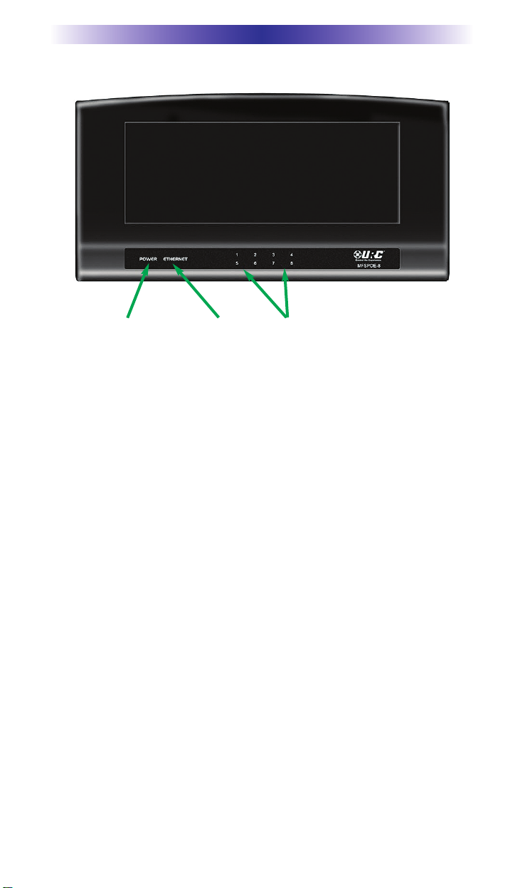
Front Panel Description
Power Indicator: Illuminates when the MFSPOE-8 Power Supply is
connected to AC outlet.
Ethernet Network Connectivity Indicator: Illuminates when the
MFSPOE-8 is connected to a LAN and has received an IP Address.
PoE Port Status Indicators: Illuminate when a PoE compliant device
is connected to a port.
MFS-8 NETWORKSWITCHINSTALLATIONMANUAL
Power
Indicator
LAN connectivity
indicator
PoE Port Status
indicators
Page 8
Page 4
Rear Panel Description
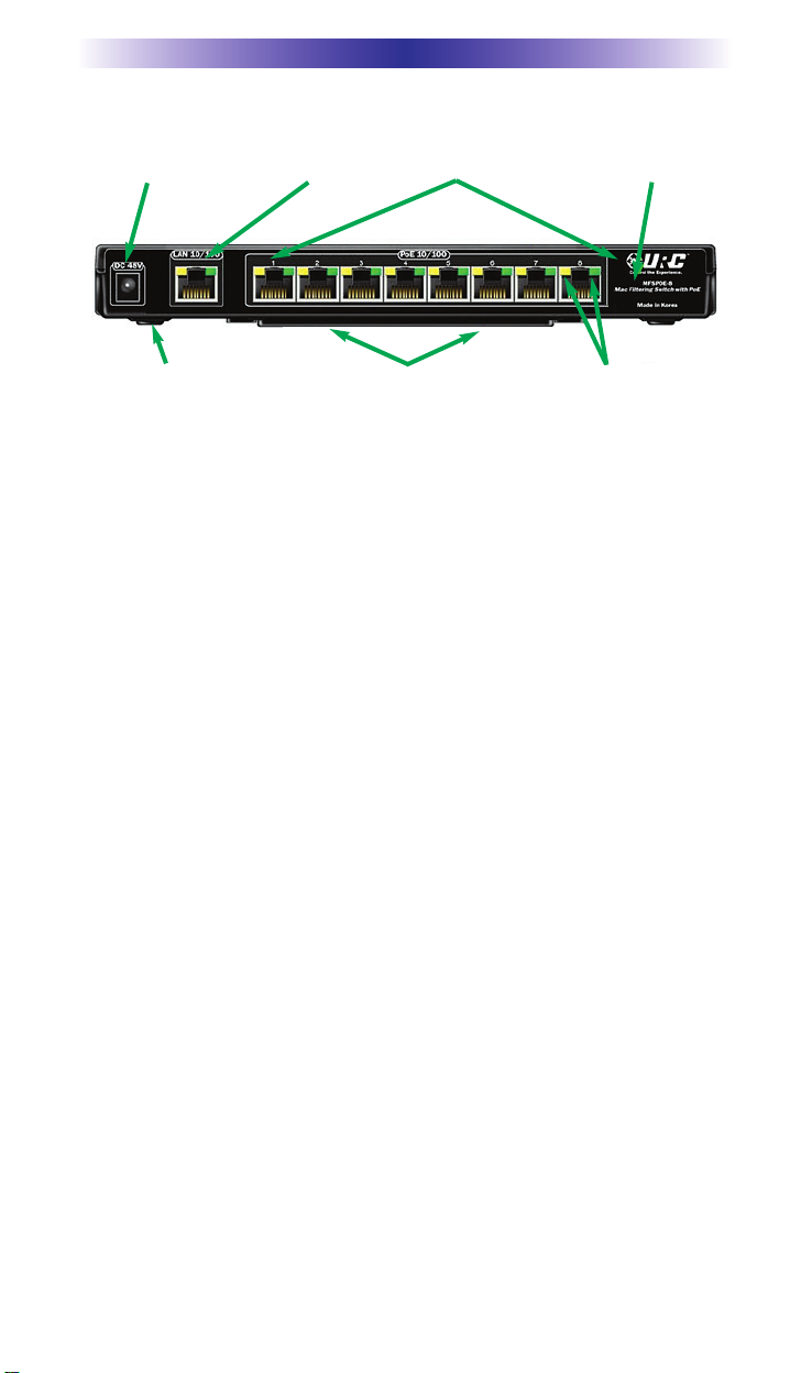
Power: Provides connection to Included 48V Power Supply.
LAN Connection: Provides connection to the LAN (Local Area
Network).
PoE 10/100 Smart Ports: 8 - PoE 10/100 Smart Ports automatically
provide power and connection to compliant PoE devices like
Keypads and IP Cameras, while simultaneously providing a safe,
non-powered connection to standard Ethernet devices.
MAC Filtering: MAC Filtering prevents multicast audio streams from
consuming network bandwidth. Streams are confined to the switch,
optimizing local area network performance.
Network Connectivity and Activity Status Indicators (port specific):
Status indicator LEDs display network connectivity and network traffic feedback, for easy troubleshooting.
Wall Mount Bracket: Convenient removable wall bracket allows the
MFSPOE-8 to be mounted to the back of a cabinet or rack. Remove
the wall bracket when placing the MFSPOE-8 on a shelf or stand.
MFS-8 NETWORKSWITCHINSTALLATIONMANUAL
Power LAN connection 8-10/100 Ports Mac Filtering
4-Soft rubber
non-scuff feet
Removable Wall Bracket
Network Status
indicator led’s
Page 9
Page 5
MFSPOE-8 Installation Considerations
Only one MAC Filtering switch should be used in a typical Total
Control system. All streaming products like the DMS-1200, DMS100 and SNP-1 mustbe connected to the switch. Other Total
Control devices that don’t stream (like the MRX-10 or the MRX-1)
don’t have to be connected to the MFS-POE-8.
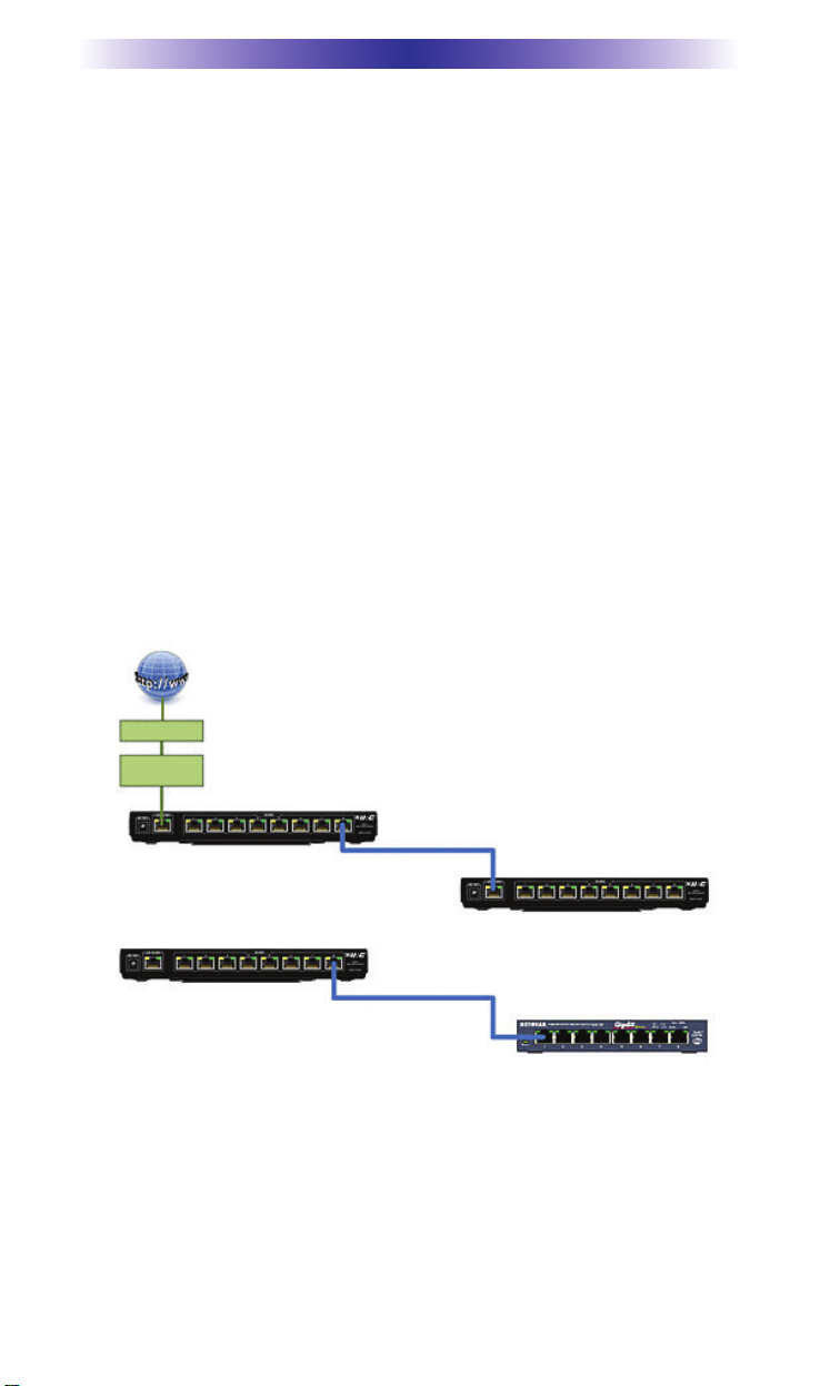
You cannot daisy-chain MFSPOE-8 MAC Filtering switches; communication between switches will be blocked. If you have more than
eight of the above streaming components, simply connect a standard network switch to any port on the MFSPOE-8 and then connect the additional components to the standard switch. This allows
the additional components to benefit from the MFSPOE-8’s MAC
Filtering, without affecting communication between devices. If you
need more PoE ports, you can plug any standard PoE network
switch into any of the available ports, to expand the network.
MFSPOE-8 NETWORKSWITCHINSTALLATIONMANUAL
X
OK
Do Not Daisy-Chain MFS-8’s
Cable Modem
Internet
Wi-Fi Router
MFS-8
MFS-8
MFS-8
Standard Network Switch
Page 10
Page 6
MFSPOE-8 NETWORKSWITCHINSTALLATIONMANUAL
Installation
1. On the back of the MFSPOE-8, connect one end of a CAT5 cable
to the port labeled LAN 10/100.
2. Connect the other end of the CAT5 cable to the LAN(Local Area
Network).
3. Connect Total Control and standard network devices to any of
the eight PoE 10/100 Smart Ports.
4. Connect the supplied 48V Power Supply to the MFSPOE-8 and
then plug it into an unswitchedAC outlet.
5. Once powered up, the unit begins working in approximately 30
seconds.
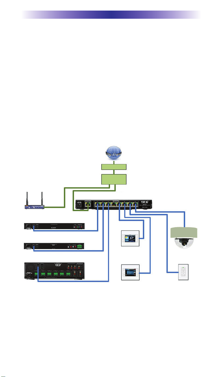
MFSPOE-8 Installed in a Small System
Notes:
The Wireless Access Point CANNOT be connected to the
MFSPOE-8; it must be connected to the Router in the LAN.
Cable Modem
Internet
Wi-Fi Router
MFSPOE-8
MAC Filtering Switch
KP-4000
KP-4000 KP-100
MC 75 CD IP
Camera 1
wireless
Access
Point
SNP-1
Streaming Network Player
DMS-100
Single Zone Digital Amp
DMS-1200
Digital Multi-Zone Amp
DMS-1200
Page 11
Page 7
MFSPOE-8 NETWORKSWITCHINSTALLATIONMANUAL
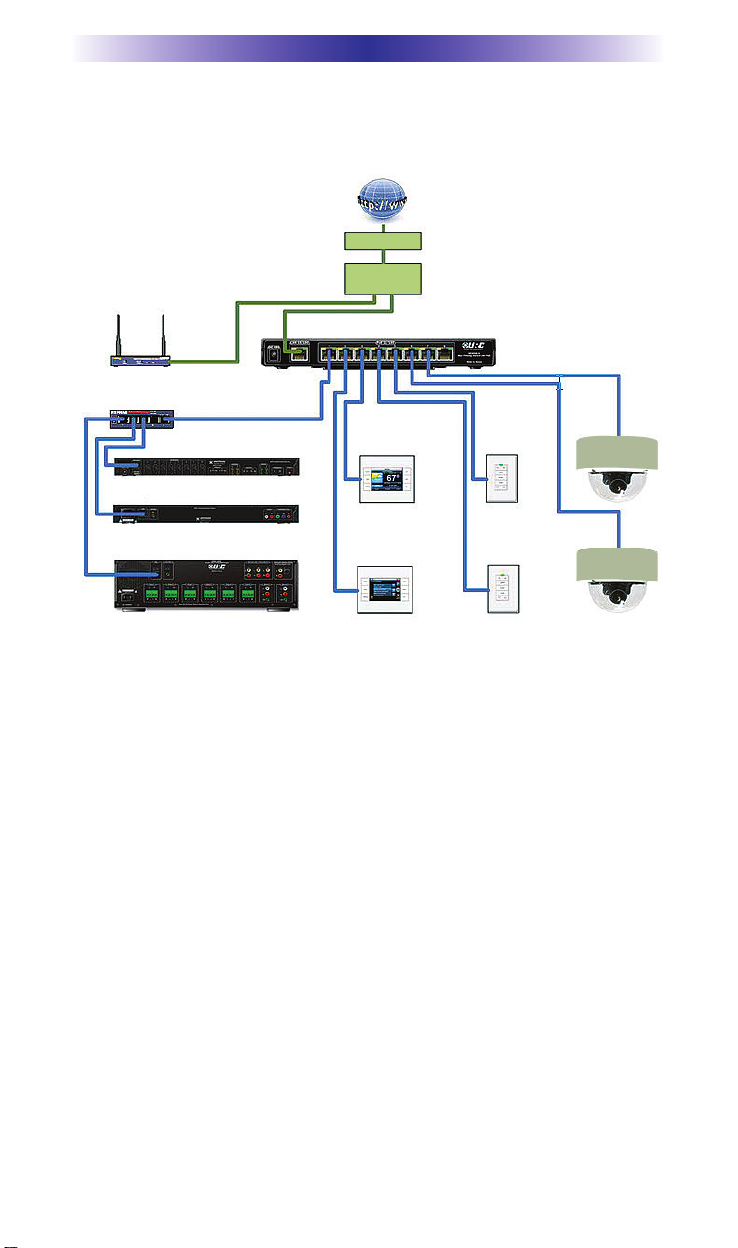
MFSPOE-8 Installation Optimized for Max Number of
PoE Ports
Notes:
The Wireless Access Point CANNOT be connected to the
MFSPOE-8; it must be connected to the Router in the LAN.
A standard network switch is used to connect the DMS-1200
and SNP-1 to the MFSPOE-8. This configuration provides
MAC Filtering to the Total Control streaming components,
while freeing up additional ports on the MFSPOE-8 to connect PoE devices like Keypads and IP Cameras.
A MRX-10 doesn’t have to be connected to the MFSPOE-8,
but can be connected to a MFSPOE-8 when convenient to do
so.
Cable Modem
Internet
Wi-Fi Router
wireless
Access
Point
DMS-1200
MFSPOE-8
MAC Filtering Switch
KP-4000
KP-100
KP-100
KP-4000
MC 75 CD IP
Camera 1
MC 75 CD IP
Camera 2
Standard Network Switch
DRX-100
Whole House Controller
SNP-1
Streaming Network Player
DMS-1200
Digital Multi-Zone Amp
Page 12
Page 8
MFSPOE-8 NETWORKSWITCHINSTALLATIONMANUAL
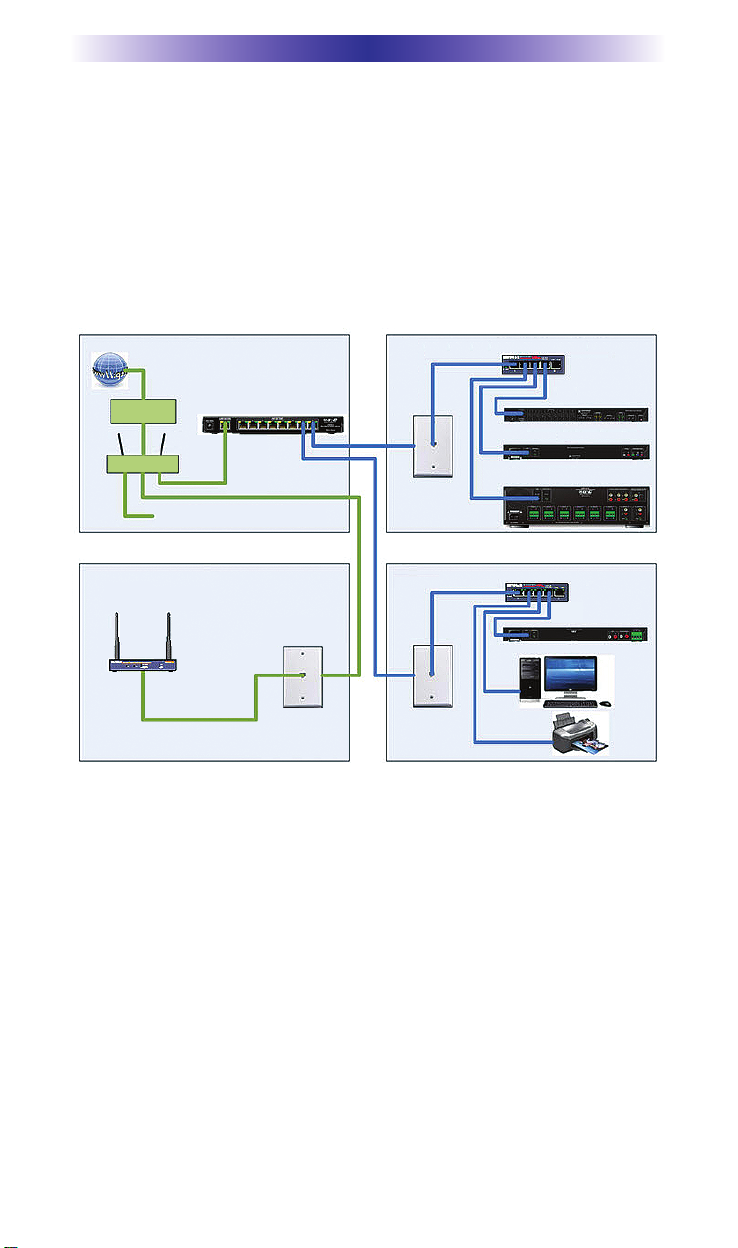
MFSPOE-8 Installed in the area with the
NetworkDistribution
Occasionally you get a retrofit installation where only one
CAT5wire has been run to a room, and there’s no way to run anotherone. In this case, locate the MFSPOE-8 in the Utility Room,
Garage,or wherever the central distribution point for the Network is
located,and install standard network switches in rooms where you
plan tolocate a DMS-1200, DMS-1200 or SNP-1.
Notes:
The Wireless Access Point CANNOT be connected to the
MFSPOE-8; it must be connected to the Router in the LAN.
Standard network switches are used to connect the DMS-
1200, DMS-100 and SNP-1 to the MFSPOE-8. This configuration provides MAC Filtering to the Total Control streaming
components, while freeing up additional ports on the
MFSPOE-8 to connect PoE devices like Keypads and IP
Cameras.
A MRX-10 doesn’t have to be connected to the MFSPOE-8,
but can be connected to a MFSPOE-8 whenconvenient to
do so.
Contral Distribution Point
for Network Wiring
Standard Network Switch
(Network for the rest of the House)
MFSPOE-8
MRX-10
Standard Network Switch
DMS-100
SNP-1
DMS-1200
Attic Office
Family Room
Cable Modem
Internet
Wi-Fi Router
wireless
Access
Point
Page 13

Page 9
MFSPOE-8 NETWORKSWITCHINSTALLATIONMANUAL
Frequently Asked Questions
Do I needto use a MFSPOE-8 in a Total Control system?
If you are only controlling a Home Theaterwith a MRX-10, and
there are no Total Control streaming sources like the DMS-1200 or
DMS-100 in the system, then the answer is NO, you do not need to
use a MFSPOE-8. If you have DMS-1200(s) or DMS-100(s) in the
system, then the answer is YES, youmustuse a MFSPOE-8 or MFS8 in the system, connected to the those components.
Can I connect both PoE (Power over Ethernet)devices and NonPoE devices to the MFSPOE-8?
Yes, the MFSPOE-8 incorporates Smart Port technology which automatically determines whether a connected device is a PoE device,
or a standard device, and only applies voltage to PoE devices. All
standard (Non-PoE) network devices can safely be connected to the
MFSPOE-8.
What if I have more than eight devices that are PoE?
You can connect a standard PoE switch anywhere on the LAN to
expand the network.
Can I use the MFSPOE-8 to power a PoE WAP (Wireless Access
Point)?
No, the WAP will not function properly when multiple streams areoccurring in the system. Connect the WAP to a standard PoE network switch, outside of the MFSPOE-8. Never connect a WAP to
the MFSPOE-8.
What if I have a large Total Control system? Should I use the
MFSPOE-8?
If you have a large Total Control system with multiple DMS-1200’s,
DMS-100’s, SNP-1’s, Keypads and IP Cameras, the better solution is
to use a MFS-8 (the Non-PoE version of the MAC Filtering switch) to
connect all the streaming products and use conventional PoE
switches to power all the Keypads and IP Cameras. See the Large
Systemdiagram in the MFS-8 User Guide for more details.
I have one CAT5 cable going to a room where my client has a network printer and a PC and I need to install a DMS-100 Single
Zone Amplifier, via the same CAT5 cable, in the room. How do I
connect everything?
Install the MFSPOE-8 in the room that contains the CAT5 distribution for the entire house. In the room where you plan to install the
Page 14

Page 10
MFSPOE-8 NETWORKSWITCHINSTALLATIONMANUAL
DMS-100, connect a standard network switch to the incoming
CAT5, and then connect the DMS-100, PC and Printer to the
switch. It is not recommended to connect PC's used for internet
gaming to a MFSPOE-8, as this may affect the performance of video
gaming during heavy stream usage.
Specifications
Microprocessor: 55MHz RISC
Memory: 4 Megabits of Serial Flash, 512KB Flash, 128KB SRAM
Network: Switching - Eight 10/100 Ethernet ports + Eight PoE ports
LAN - One 10/100 Ethernet port
Power Supply: 48V External Power Supply
POWER OUT: 8 Port POE OUTPUT(6.2W*8=50W, 1PORT
MAX=15.4W)
Size: 1.5” x 9.8” x 4.9” (H X W x D)
Weight: 0.78 lbs. (0.35kg)
Page 15

Page 11
MFSPOE-8 NETWORKSWITCHINSTALLATIONMANUAL
USA Limited Warranty Statement
Your Universal Remote Control, when delivered to you in new condition, is warranted against defects in materials or workmanship as
follows: UNIVERSAL REMOTE CONTROL, INC.warrants this prod-
uct against defects in material or workmanship for s period of one
(1) year and as set forth below. Universal Remote Control will, at its
sole option, repair the product using new or comparable rebuiltparts, or exchange the product for a comparable new or rebuiltproduct. In the event of a defect, these are your exclusive reme-
dies.
This Limited Warranty covers only the hardware components packaged with the Product. It does not cover technical assistance for
hardware or software usage and it does not cover any softwareproducts whether or not contained in the Product; any such software is provided “AS IS” unless expressly provided for in any
enclosed software Limited Warranty.
To obtain warranty service, you must deliver the product, freightprepaid, in its original packaging or packaging affording adequate
protection to Universal Remote Control at the address provided in
the Owner’s Manual. It is your responsibility to backup any
macroprogramming, artwork, software or other materials that may
havebeen programmed into your unit. It is likely that such data,
soft-ware, or other materials will be lost during service and Universal
Remote Control will not be responsible for any such damage or
loss. A dated purchase receipt, Bill of Sale, Installation Contract or
other verifiable Proof of Purchase is required. For product supportand other important information visit Universal Remote Control’s
website: http://www
.UniversalRemote.com or call the Customer
Service Center (914) 835-4484.
This Limited Warranty only covers product issues caused by defects
in material or workmanship during ordinary consumer use. It doesnot cover product issues caused by any other reason, including butnot limited to product issues due to commercial use, acts of God,
third-party installation, misuse, limitations of technology, or modification of or to any part of the Universal Remote Control product.
This Limited Warranty does not cover Universal Remote Control
products sold as USED, AS IS, REFURBISHED, so-called “B STOCK”
or consumables (such as batteries). This Limited Warranty is invalid
if the factory-applied serial number has been altered or removed
from the product. This Limited Warranty is valid only in the United
States of America. This Limited Warranty specifically excludes prod-
ucts sold by unauthorized resellers.
Page 16

Page 12
Federal Communication Commission
Interference Statement
This equipment has been tested and found to comply with the limits for a
Class B digital device, pursuant to part 15 of the FCC Rules. These limits are
designed to provide reasonable protection against harmful interference in a
residential installation. This equipment generates, uses and can radiate radio
frequency energy and, if not installed and used in accordance with the instructions, may cause harmful interference to radio communications. However,
there is no guarantee that interference will not occur in a particular installation. If this equipment does cause harmful interference to radio or television
reception, which can be determined by turning the equipment off and on, the
user is encouraged to try to correct the interference by one more of the following measures:
Reorient or relocate the receiving antenna.
Increase the separation between the equipment and receiver.
Connect the equipment into an outlet on a circuit different from
that to which the receiver is connected.
Consult the dealer or an experienced radio/TV technician for
help.
Warning!
Changes or modifications not expressly approved by the manufacturer could
void the user's authority to operate the equipment.
Note : The manufacturer is not responsible for any Radio or TV interference
caused by unauthorized modifications to this equipment. Such modifications
could void the user's authority to operate the equipment.
FCC Caution
This device complies with Part 15 of the FCC Rules. Operation is subject to the
following two conditions: (1) this device may not cause harmful interference,
and (2) this device must accept any interference received, including interference
that may cause undesired operation.
Any changes or modifications not expressly approved by the party responsible
for compliance could void the authority to operate equipment.
MFSPOE-8 NETWORKSWITCHINSTALLATIONMANUAL
Page 17
Page 13
MFSPOE-8 NETWORKSWITCHINSTALLATIONMANUAL
Regulatory Information to the user
CE conformity Notice
Products with “CE” marking comply EMC Directive 2004/108/EC issued
by the commission of the European Community.
1) EMC Directive
Emission : EN 55022
Immunity : EN 55024
Power : EN-61000-3-2, 3
Declaration of Conformity
“Hereby, Universal Remote Control Inc. declares that this MFSPOE-8 is
in compliance with the Essential requirements and other relevant provisions of EMC Directive 2004/108/EC.”
Certification
Type No.(Model No.) MFSPOE-8
Batch/Serial No. Power Rating 48.0V , 1.25A
Page 18

Declaration of Conformity
Company Name : Universal Remote Control Inc.
Company Address : 500Mamaroneck Avenue, Harrison, NY 10528, U.S.A
Contact Info rmation :
www
.universalremote.com
Phone: (914)835-4484 Fax: (914)835-4532
Brand Name : UNIVERSAL remote control
Product Name : Mac Filtering Switch with PoE
Model Name : MFSPOE-8
This product herewith complies with the requirements of EMC Directive (2004/108/EC)
issued bythe Commission of the European Community
Compliance with these directives implies conformity to the following European Community
EMC Directive
EN 55022
EN 55024
EN 61000-3-2
EN 61000-3-3
List of test reports and/or certificate verified compliance with the standards above
Date of issue : November 09. 2010
Name and signature of authorized person :
EMC Directive
Report No.
Testi ng Labora tory : Gumi College EMC Center
James Novak
Senior Product Manager
Universal Remote Control Inc.
Page 14
MFSPOE-8 NETWORKSWITCHINSTALLATIONMANUAL
Page 19

500 Mamaroneck Avenue, Harrison, NY 10528
Phone: (914) 835-4484 Fax: (914) 835-4532
www.universalremote.com
OCE-0076C Rev 01
 Loading...